1, Hardware
STM32F103C8T6, thermistor sensor, OLED.
2, Introduction of thermistor sensor
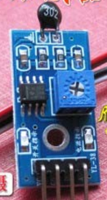
A DO output port outputs digital quantity, and outputs 0 or 1 according to whether the external temperature exceeds the threshold of the sensor; An AO port outputs analog quantity. The detection of temperature shall be realized through analog quantity conversion.
3, Code implementation
In order to convert the analog quantity read by the single chip microcomputer into temperature, the following steps need to be taken: 1. Convert the read value to voltage; 2. Voltage to resistance 3. Calculate the actual temperature according to the formula.
1. ADC read. How to read ADC can be seen from the previous article on reading photoresist. The process is similar, but the pins are different. The code is as follows.
//Initialize ADC
//Here we only take the regular channel as an example
//We will open channels 0 ~ 3 by default
void  temp_Adc_Init(void)
{
    ADC_InitTypeDef ADC_InitStructure;
    GPIO_InitTypeDef GPIO_InitStructure;

    RCC_APB2PeriphClockCmd(RCC_APB2Periph_GPIOA |RCC_APB2Periph_ADC1, ENABLE );      //Enable ADC1 channel clock


    RCC_ADCCLKConfig(RCC_PCLK2_Div6);   //Set ADC frequency division factor 6 72m / 6 = 12, and the maximum ADC time cannot exceed 14M

    //PA1 as analog channel input pin
    GPIO_InitStructure.GPIO_Pin = GPIO_Pin_6;
    GPIO_InitStructure.GPIO_Mode = GPIO_Mode_AIN;        //Analog input pin
    GPIO_Init(GPIOA, &GPIO_InitStructure);

    ADC_DeInit(ADC1);  //Reset ADC1 and reset all registers of peripheral ADC1 to the default value

    ADC_InitStructure.ADC_Mode = ADC_Mode_Independent;    //ADC working mode: ADC1 and ADC2 work in independent mode
    ADC_InitStructure.ADC_ScanConvMode = DISABLE;    //Analog to digital conversion works in single channel mode
    ADC_InitStructure.ADC_ContinuousConvMode = DISABLE;    //Analog to digital conversion works in single conversion mode
    ADC_InitStructure.ADC_ExternalTrigConv = ADC_ExternalTrigConv_None;    //The conversion is initiated by software rather than an external trigger
    ADC_InitStructure.ADC_DataAlign = ADC_DataAlign_Right;    //ADC data right alignment
    ADC_InitStructure.ADC_NbrOfChannel = 6;    //The number of ADC channels that perform rule conversion sequentially
    ADC_Init(ADC1, &ADC_InitStructure);    //According to ADC_ Initializes the register of the peripheral ADCx with the parameters specified in initstruct

    ADC_Cmd(ADC1, ENABLE);    //Enables the specified ADC1
    ADC_ResetCalibration(ADC1);    //Enable reset calibration
    while(ADC_GetResetCalibrationStatus(ADC1));    //Wait until reset calibration is complete
    ADC_StartCalibration(ADC1);     //Turn on AD calibration
    while(ADC_GetCalibrationStatus(ADC1));     //Wait until calibration is complete
    ADC_SoftwareStartConvCmd(ADC1, ENABLE);        //Enable the software conversion startup function of the specified ADC1
}
//Obtain ADC value
//ch: channel value 0 ~ 3
u16 temp_Get_Adc(u8 ch)
{
      //Set the rule group channel, a sequence and sampling time of the specified ADC
    ADC_RegularChannelConfig(ADC1, ch, 1, ADC_SampleTime_239Cycles5 );    //ADC1,ADC channel, sampling time 239.5 cycles
    ADC_SoftwareStartConvCmd(ADC1, ENABLE);        //Enable the software conversion startup function of the specified ADC1
    while(!ADC_GetFlagStatus(ADC1, ADC_FLAG_EOC ));//Wait for the conversion to end
    return ADC_GetConversionValue(ADC1);           //Returns the last conversion result of ADC1 rule group
}

u16 temp_Get_Adc_Average(u8 ch,u8 times)
{
    u32 temp_val=0;
    u8 t;
    for(t=0;t<times;t++)
    {
        temp_val+=temp_Get_Adc(ch);
        Delay_ms(5);
    }
    return temp_val/times;
}
2. Sampling value to voltage and resistance
For voltage calculation, the STM32F103C8T6 I use uses 12 bit ADC sampling, so the maximum sampling value is 2 ^ 12 = 4096, while the voltage of the single chip microcomputer is 3.3v, so the read voltage = the read sampling value / 4096 * 3.3V.
Find the resistance, as shown in the figure
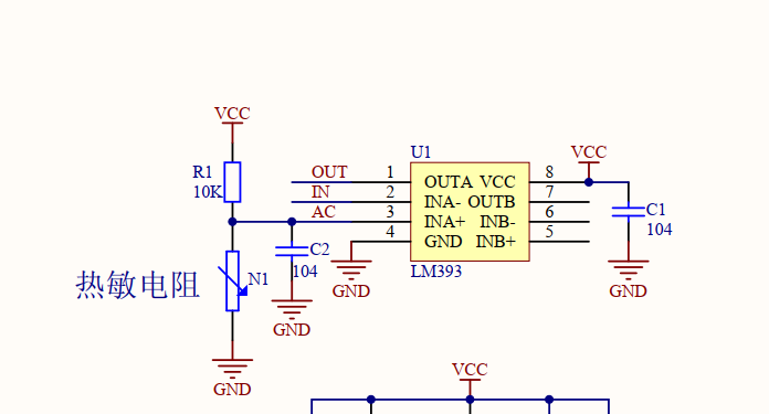
vcc = 3.3V, the voltage of the thermistor is calculated above, and the current resistance value of the thermistor can be known by calculating the ratio
The code is as follows
//Analog to resistance
float temp_Get_R(u16 adct)
{
	//MCU 3.3v power supply = = "3v", calculate the voltage first
	float v1 = (float)(adct*3.3)/4096;//Voltage on ntc
	float v2 = 3.3 - v1;
	float r = (v1/v2)*10;

	return r;
}
3. Temperature calculation
According to the Kelvin formula, the current Kelvin temperature Tn can be directly obtained as follows: B=(lnR25 - lnRntc)/(1/T25 - 1/Tn)
Among them, the single chip microcomputer cannot use math h. So the logarithmic function should be implemented by itself.
Parameter introduction:
B. It is a coefficient related to the coefficient of thermistor itself (Baidu said it was provided by the manufacturer), 3435 (just ask the seller)
R25 is the resistance of the pull-up resistor,
Rntc is the resistance of the thermistor calculated above
T25: Kelvin temperature at 25 ℃, i.e. 298.15K
Tn: actual Kelvin temperature calculated at this time (C=Tn-273.15)
The code is as follows
Some parameters defined in header price
#define T25 298.15 / / application of voltage to temperature formula
#define R25 10
#define B	3435
//The calculation of ln(x) is realized
double myln(double a)
{
   int N = 15;//The first 15 + 1 items are taken to estimate
   int k,nk;
   double x,xx,y;
   x = (a-1)/(a+1);
   xx = x*x;
   nk = 2*N+1;
   y = 1.0/nk;
   for(k=N;k>0;k--)
   {
     nk = nk - 2;
     y = 1.0/nk+xx*y;

   }
   return 2.0*x*y;
}

float Get_Kelvin_Temperature(u16 t)
{
	float N1,N2,N3,N4;
	float Rntc = temp_Get_R(t);
	N1 = (myln(R25)-myln(Rntc))/B;
	N2 = 1/T25 - N1;
	N3 = 1/N2;
	N4 = N3-273.15;//Kelvin to Celsius

	return N4;
}
4. Main function
float temp2 = Get_Kelvin_Temperature(adct);
u16 t = (u16)temp2;
OLED_ShowNum(1,7,t,4);//The working range is 20-80
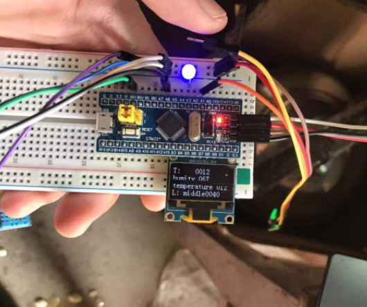
4, Physical condition
T is the temperature measured by thermistor 12 degrees
Temperature is the temperature measured by DHT11 before, 12 degrees. The error between the two is very small, which shows that ok the family....