Test chip: STM32L151RCT6
Problem Description:
After I initialize the input capture timer, I input PWM pulse at the input capture pin when the timer is not enabled. It is found that the capture flag (CC1IF) of the capture timer is set and the interrupt is entered at the same time. Reference is attached.
Problem analysis:
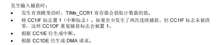
At the beginning of this phenomenon, I was very confused. How can I enter the capture interrupt before I enable the capture timer? There is no information to find relevant questions on the Internet, so we can only find the answers from the manual. After looking for a long time, the manual does not directly say why this is the case. However, when I look at the timer enable bit Cen, I probably understand that the cen bit is called counter enable, and set 1 to counter TIMx_CNT starts to increase or decrease. It can be seen that this bit mainly makes the timer counter work. For most applications, this Cen bit is not set to 1, and many functions cannot run. However, this is not the case for timer capture. After you configure the capture parameters, that is, after this channel is enabled (timx - > CCER corresponding channel is set), The capture channel has actually started working. When the capture channel detects the rising edge or falling edge, it will set the relevant flag, that is, this part of the circuit works independently. Whether CEN is set or not affects whether the capture value (timx - > CCR1) read after entering the capture interrupt is correct. When CEN is 0, the data collected is 0 because the counter does not work for many times.
Reference code:
/**
  * Description: used to capture rising edge
  * Parameter: None
  * Return: None
  */
void Cap_Timer_Init(void)
{
    LL_TIM_IC_InitTypeDef TIM_IC_InitStruct = {0};
    LL_GPIO_InitTypeDef GPIO_InitStruct = {0};

	LL_AHB1_GRP1_EnableClock(LL_AHB1_GRP1_PERIPH_GPIOA);
    LL_APB1_GRP1_EnableClock(LL_APB1_GRP1_PERIPH_TIM2);

	/** CAP_CH1->PA0->TIM2_CH1 */
	GPIO_InitStruct.Pin=LL_GPIO_PIN_0;
	GPIO_InitStruct.Mode=LL_GPIO_MODE_ALTERNATE;
	GPIO_InitStruct.Speed=LL_GPIO_SPEED_FREQ_HIGH;
	GPIO_InitStruct.Pull=LL_GPIO_PULL_NO;
	GPIO_InitStruct.Alternate=LL_GPIO_AF_1;
	LL_GPIO_Init(GPIOA, &GPIO_InitStruct);

	/** Cap_IN->PA1->TIM2_CH2 */
	GPIO_InitStruct.Pin=LL_GPIO_PIN_1;
	LL_GPIO_Init(GPIOA, &GPIO_InitStruct);

	/** Timer time base configuration */
	LL_TIM_SetPrescaler(TIM2, 0);
	LL_TIM_SetAutoReload(TIM2, 65535);
	LL_TIM_SetCounterMode(TIM2, LL_TIM_COUNTERMODE_UP);
    LL_TIM_EnableARRPreload(TIM2);
    LL_TIM_SetClockSource(TIM2, LL_TIM_CLOCKSOURCE_INTERNAL);

	/** Input capture parameter settings */
	TIM_IC_InitStruct.ICActiveInput = LL_TIM_ACTIVEINPUT_DIRECTTI;
	TIM_IC_InitStruct.ICFilter = LL_TIM_IC_FILTER_FDIV1;
	TIM_IC_InitStruct.ICPolarity = LL_TIM_IC_POLARITY_RISING;
	TIM_IC_InitStruct.ICPrescaler = LL_TIM_ICPSC_DIV1;
	LL_TIM_IC_Init(TIM2, LL_TIM_CHANNEL_CH1, &TIM_IC_InitStruct);
	/** Enable channel */
	LL_TIM_CC_EnableChannel(TIM2, LL_TIM_CHANNEL_CH1);

	/** Configuration interrupt */
    LL_TIM_EnableIT_CC1(TIM2);
	LL_TIM_EnableIT_UPDATE(TIM2);
    NVIC_EnableIRQ(TIM2_IRQn);
	NVIC_SetPriority(TIM2_IRQn, NVIC_EncodePriority(NVIC_GetPriorityGrouping(), 2, 0));

	LL_TIM_GenerateEvent_UPDATE(TIM2);
	LL_TIM_ClearFlag_CC1(TIM2);
	LL_TIM_ClearFlag_UPDATE(TIM2);
//	LL_TIM_EnableCounter(TIM2); 	/**  Do not enable*/

}

/**
  * Description: Timer 2 interrupt service function (capture)
  * Parameter: None
  * Return: None
  */
void TIM2_IRQHandler(void)
{
	if(LL_TIM_IsActiveFlag_CC1(TIM2) != RESET)
	{
		Debug.cap = LL_TIM_IC_GetCaptureCH1(TIM2);
		LL_TIM_DisableCounter(TIM2);
		PC10_Toggle();
		Debug.status=0xAA;
	}
	if(LL_TIM_IsActiveFlag_UPDATE(TIM2) != RESET)
	{
		LL_TIM_ClearFlag_UPDATE(TIM2);
		LL_TIM_DisableCounter(TIM2);
		PC11_Toggle();
		Debug.status=0xFF;
	}
}
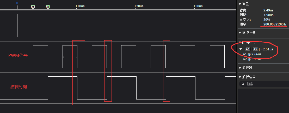
Test results:
Input PWM to PA0 will generate capture interrupt, but the read capture value is 0. And from the results, the time of capture is not the rising edge (this is very strange, because what I said above is a little wrong, I think it should be captured on the rising edge). Therefore, the above analysis is limited to my personal opinion.
The timing waveform is as follows: