preface
This design mainly introduces the single chip microcomputer program design idea and circuit design of intersection traffic lights
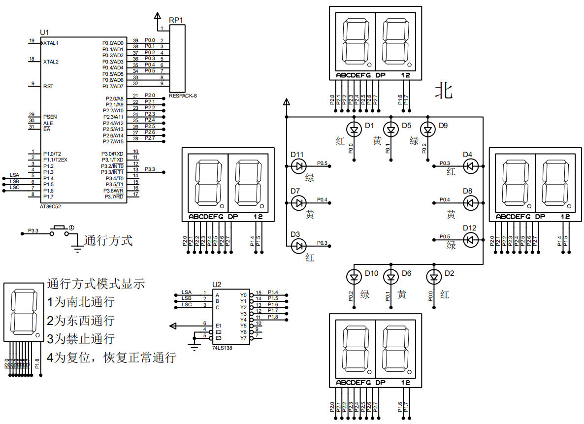
circuit design
Generally speaking, the circuit design of traffic lights is relatively simple. It mainly depends on whether the designer wants to realize more functional intelligent traffic lights. If it is simple, it only needs an AT89C52 single chip microcomputer and the corresponding LED lights and nixie tube display module.
This simple circuit I designed only uses a 74LS138 decoder, four eight segment nixie tubes with two common cathodes to display the delay time in four directions respectively, and an eight segment nixie tube with common cathodes to display the selected functions, four red, yellow and blue LED lamps respectively, plus an AT89C52 single chip microcomputer.
The final functions of the circuit include normal traffic at the intersection, north-south traffic, east-west traffic and no traffic.
The circuit design drawings are as follows:
 Programming ideas
This program is relatively simple on the whole. It can be written in three modules
1. Nixie tube display module, the display module is controlled by 74LS138 decoder, that is, just write a driver of 74LS138 decoder.
2. Alternating change display program of LED lamp.
3. Function implementation program. External interrupt 1 is used here to achieve the purpose.
working principle
When the system is powered on, the green light in the east-west direction is 25s, the red light in the north-south direction is 30s, the green light in the east-west direction is 25s, the yellow light in the east-west direction is 5S, the yellow light in the east-west direction is 30s, the green light in the north-south direction is 25s, the green light in the north-south direction is 25s, and then the green light in the east-west direction is 25s, and the green light in the north-south direction is 30s, and the cycle is carried out in turn. The delay time is displayed through the nixie tube.
Function selection: press the key to trigger external interrupt 1 and change the interrupt variable to realize the corresponding function. When the interrupt variable is 0, it is displayed normally. When the interrupt variable is 1, only north-south traffic is allowed, east-west traffic is prohibited, when the interrupt variable is 2, only east-west traffic is allowed, South-North traffic is prohibited, and when the interrupt variable is 3, traffic is prohibited in four directions of southeast, northwest and northwest, In order to ensure safety, the conversion can only be carried out after the normal cycle being executed before the conversion function.
Programming
main program
#include <reg52.h>
#include <intrins.h>

typedef unsigned int uint;
typedef unsigned char uchar;
void dispaly_smg();
void Zhenchang();
//Define north-south display nixie tube I/O port
#define smg P2
#define LED P0
//Define key IO port
sbit key=P3^3;
//Define 74LS138 decoder I/O segment
sbit LSA=P1^4;
sbit LSB=P1^5;
sbit LSC=P1^6;

uchar code smg_duan[]={0x3f,0x06,0x5b,0x4f,0x66,0x6d,0x7d,0x07,0x7f,0x6f,0x77,0x7c,0x39,0x5e,0x79,0x71,0x00};
//Define segment codes 0~F of common cathode nixie tube
uchar key_num;      //Store key variables
uchar temp0;      //Interrupt count variable
uchar temp1,temp2;     //temp1 East-West time display, temp2 north-south time display
uchar flag0;     //Normally displayed variables
uchar flag1;    //Function selection interrupt variable

void delay(uint i)    //Software delay subroutine
{
	while(i--);
}

void main()   //main program
{
	Time_Init();   //Call timer and external interrupt 1 initialization subroutine
	while(1)
	{
		if(flag1==0)
		{
			smg=0x00;
			delay(50);
			Zhenchang();    //Normal operation display
		}
		else if(flag1==1)
		{
			LED=0xf3;      //North south traffic
			dispaly_smg();    //Nixie tube display subroutine
		}
		else if(flag1==2)
		{
			LED=0xde;     //East West passage
			dispaly_smg();
		}
		else if(flag1==3)
		{
			LED=0xf6;      //No Entry
			dispaly_smg();
		}
	}
}
Nixie tube display subroutine
void dispaly_smg()   //Nixie tube display function
{
//74LS138 decoder driver
	uchar i;
	for(i=0;i<5;i++)
	{
		switch(i)
		{
			case 0:
				LSA=0;LSB=0;LSC=0;smg=smg_duan[temp1/10];break;    //East west travel time display
			case 1:
				LSA=1;LSB=0;LSC=0;smg=smg_duan[temp1%10];break;
			case 2:
				LSA=0;LSB=1;LSC=0;smg=smg_duan[temp2/10];break;   //North south travel time display
			case 3:
				LSA=1;LSB=1;LSC=0;smg=smg_duan[temp2%10];break;
			case 4:
				LSA=0;LSB=0;LSC=1;smg=smg_duan[flag1];break;  //Display function selection value
		}
		delay(50);
		smg=0x00;    //Nixie tube blanking
		delay(50);
	}
}
Normal display subroutine
void Zhenchang()
{

	switch(flag0)
	{
		case 0:
			temp1=25;temp2=30;  //Initial values are displayed in both directions
			LED=0xde;   //East West Green, North South Red
			while(temp1!=0)
			{
				dispaly_smg();    //Delay time display
				if(temp0==100)    //Judge whether the timer interrupt variable reaches 100 times, that is, timing for 1s
				{
					temp1--;   //temp1, temp2 number minus 1, temp0 is cleared
					temp2--;
					temp0=0;
				}
			}
			flag0++;    //Variable plus one
			break;
		case 1:
			temp1=5;    //East west direction yellow light display assignment
			LED=0xee;    //Yellow lights from east to west, red lights from north to South
			while(temp1!=0)
			{
				dispaly_smg();
				if(temp0==100)
				{
					temp1--;
					temp2--;
					temp0=0;
				}
			}
			flag0++;
			break;
		case 2:
			temp1=30;temp2=25;
			LED=0xf3;   //East West red light, North South green light
			while(temp2!=0)
			{
				dispaly_smg();
				if(temp0==100)
				{
					temp1--;
					temp2--;
					temp0=0;
				}
			}
			flag0++;
			break;
		case 3:
			temp2=5;
			LED=0xf5;   //East West red light, North South Yellow Light
			while(temp2!=0)
			{
				dispaly_smg();
				if(temp0==100)
				{
					temp1--;
					temp2--;
					temp0=0;
				}
			}
			flag0=0;
			break;
	}
}
Timer interrupt initialization, external interrupt initialization subroutine and interrupt service program
void Time_Init()    //Timer interrupt 0 is initialized with external interrupt 1
{
	EA=1;    //Open total interrupt
	TMOD=0x01;    //Select the working mode of the timer. The working mode is mode 1
	ET0=1;    //Turn on timer 0 interrupt switch
	TR0=1;      //Turn on timer 0 to do things
	TH0=0xdc;    //Load the initial value, and the initial value is 10ms
	TL0=0x00;

	IT1=1;   //Open external interrupt 1
	EX1=1;    //Turn on the interrupt switch of external interrupt 1
}

void time() interrupt 1    //Timer interrupt reset procedure
{
	TH0=0xdc;    //Load initial value
	TL0=0x00;
	temp0++;      //Timer interrupt variable + 1
}

void Init() interrupt 2     //External interrupt 1 service routine
{
	P3=0xff;     //P3 port is all pulled up
	if(key==0)    //Is the key pressed
	{
		delay(1000);    //Debounce
		if(key==0)    //Judge whether to press again
		{
			while(!key);   //Judge whether the key is released
			flag1++;     //Change function selection variable
			if(flag1==4)
				flag1=0;  //When the variable is equal to 4, it is cleared and reset
		}
	}
}
The above is all the basic procedures for all traffic light control. You can also change the above procedures to make them more perfect. For example, you can add a series of functions such as traffic lights on crosswalks, flashing yellow lights to remind people that the time is coming and so on. Learning is endless. Programming is not difficult. The difficulty lies in persistence. Write more and learn more. Always ensure that your brain has a clear thinking ability and understanding ability.