overview
One feature of SBL is Customizable, which is divided into pre build and post build customization.
SBL has two kinds of configuration data, namely internal configuration data and external configuration data. Internal configuration data is the default data written in the code. This default data is used when external data cannot be obtained; External configuration data is generated from predefined files and configuration tools.
Predefined files and configuration tools in SBL include:
- YAML file: it defines the configuration;
- DLT (delta, which actually represents variable data) file: Override data, which is used to overwrite the configuration in YAML file;
- Configuration operation tools: usually Python scripts.
YAML file
YAML file contains memory, Silicon, GPIO, startup policy, security configuration, etc.
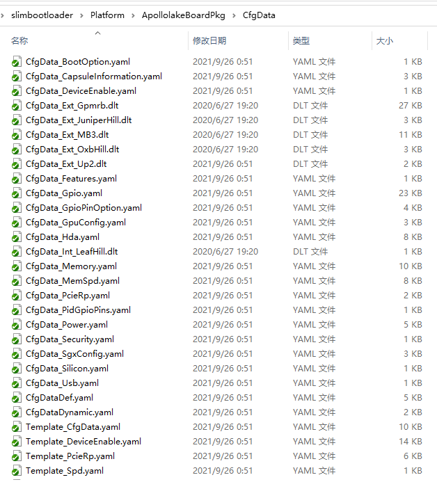
YAML files are usually contained in a specific board directory, such as the Apollo Lake platform:
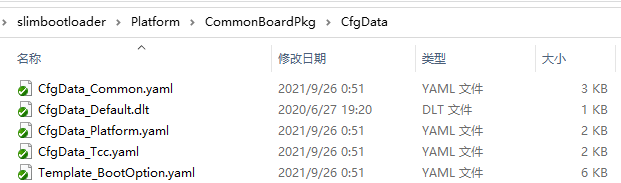
There are also some general YAML files in the Platform\CommonBoardPkg\CfgData Directory:
The configuration file entry required by the platform is CfgDataDef.yaml, and other configuration files are included in CfgDataDef.yaml as its sub files. For example, platform \ Apollo lakeboardpkg \ cfgdata \ CfgDataDef.yaml:
## @file
#
#  Slim Bootloader CFGDATA Default File.
#
#  Copyright (c) 2020, Intel Corporation. All rights reserved.<BR>
#  SPDX-License-Identifier: BSD-2-Clause-Patent
#
##

variable:
  COND_GPIO_SKIP                 : ($GPIO_CFG_DATA.$(1)_Half0.GpioSkip == 0)
  COND_GPIO_PID_ENABLE           : ($PID_GPIO_CFG_DATA.$(1).Enable==1) and ($PLATFORMID_CFG_DATA.PlatformId==0)
  COND_PCIE_RP_PWR_PIN_SKIP      : ($PCIE_RP_CFG_DATA.PcieRpPower$(1).Skip == 0)
  COND_PCIE_RP_RST_PIN_SKIP      : ($PCIE_RP_CFG_DATA.PcieRpReset$(1).Skip == 0)
  COND_PCIE_RP_EN                : ($PCIE_RP_CFG_DATA.PcieRpFeatures$(1).En == 1)
  COND_PCIE_RP_CLK_REQ_SUP       : (($PCIE_RP_CFG_DATA.PcieRpFeatures$(1).ClkReqSup == 1) and ($PCIE_RP_CFG_DATA.PcieRpFeatures$(1).En == 1))
  COND_HDA_EN                    : ($HDA_CFG_DATA.HdaEnable == 1)
  COND_HDA_DSP_EN                : (($HDA_CFG_DATA.HdaEnable == 1) and ($HDA_CFG_DATA.DspEnable == 1))

template:

  - !include Template_CfgData.yaml

configs:
  - $ACTION      :
      page         : PLT::"Platform", MEM::"Memory Settings", SIL::"Silicon Settings", GEN::"General Settings", GIO::"Gpio Settings", OS::"OS Boot Options"
  - Signature    :
      length       : 0x04
      value        : {'CFGD'}
  - HeaderLength :
      length       : 0x01
      value        : 0x10
  - Reserved     :
      length       : 0x03
      value        : {0,0,0}
  - UsedLength   :
      length       : 0x04
      value        : _LENGTH_
  - TotalLength  :
      length       : 0x04
      value        : 0x2000

  - !include Platform/CommonBoardPkg/CfgData/CfgData_Platform.yaml

  - $ACTION      :
      page         : IOCUART:PLT:"IOC Uart Settings"
  - $ACTION      :
      page         : IOCUART
  - IOC_UART_CFG_DATA :
    - !expand { CFGHDR_TMPL : [ IOC_UART_CFG_DATA, 0x120, 0, 0 ] }
    - DeviceIndex  :
        name         : Device Index
        type         : Combo
        option       : 0:UART0, 1:UART1, 2:UART2, 3:UART3, 0xF:Disable
        help         : >
                       UART device index for IOC interface (0..3 or Disable)
        length       : 0x01
        value        : 0xF
    - BaudRate     :
        name         : Baud Rate
        type         : Combo
        option       : 0:9600, 1:19200, 2:38400, 3:57600, 4:115200, 5:921600, 6:1.5M
        help         : >
                       UART Baud Rate
        length       : 0x01
        value        : 0
    - Retries      :
        name         : Retries
        type         : EditNum, HEX, (0x00,0xFF)
        help         : >
                       specify retry count
        length       : 0x01
        value        : 0
    - TimeoutInitial :
        name         : TimeoutInitial
        type         : EditNum, HEX, (0x00,0xFF)
        help         : >
                       initial/setup time-out (in milliseconds)
        length       : 0x01
        value        : 0
    - TimeoutXmit  :
        name         : TimeoutXmit
        type         : EditNum, HEX, (0x00,0xFF)
        help         : >
                       transmission time-out
        length       : 0x01
        value        : 0
    - Rsvd         :
        length       : 0x03
        value        : 0

  - $ACTION      :
      page         : PSEL:PLT:"Payload Selection GPIO"
  - $ACTION      :
      page         : PSEL
  - PLATFORM_CFG_DATA :
    - !expand { CFGHDR_TMPL : [ PLATFORM_CFG_DATA, 0x280, 0, 0 ] }
    - PayloadSelGpio :
      - $STRUCT      :
          name         : GPIO pin for switching payload
          struct       : PAYLOAD_SEL_GPIO_PIN
          length       : 0x04
          value        : 0x000000c5
      - PadInfo      :
          name         : Pin Number
          type         : Combo
          option       : !include CfgData_GpioPinOption.yaml
          condition    : ($PLATFORM_CFG_DATA.PayloadSelGpio.Enable > 0)
          help         : >
                         Specify GPIO Pin Number
          length       : 24b
      - Rsvd1        :
          name         : Reserved
          type         : Reserved
          length       : 7b
      - Enable       :
          name         : Payload Selection Pin Enable
          type         : Combo
          option       : $EN_DIS
          help         : >
                         Enable/Disable this pin for payload selection.
          order        : 0000.0000
          length       : 1b

  - !include CfgData_Memory.yaml
  - !include CfgData_Silicon.yaml
  - !include CfgData_Usb.yaml
  - !include CfgData_Gpio.yaml
  - !include Platform/CommonBoardPkg/CfgData/CfgData_Common.yaml
  - !include CfgData_BootOption.yaml
  - !include CfgData_PidGpioPins.yaml
  - !include CfgData_PcieRp.yaml
  - !include CfgData_GpuConfig.yaml
  - !include CfgData_Features.yaml
  - !include CfgData_DeviceEnable.yaml
  - !include CfgData_Hda.yaml
  - !include CfgData_CapsuleInformation.yaml
You can see that there are many include commands, specifying YAML files such as memory, Silicon, USB, GPIO, etc.
DLT file
The data in the DLT file is used to overwrite the configuration in the YAML file.
The DLT file contains a PlatformId, such as platform \ Apollo lakeboardpkg \ cfgdata \ cfgdata_ Ext_ In up2.dlt:
#
# Delta configuration values for platform ID 0x000E
#
PLATFORMID_CFG_DATA.PlatformId           | 0x000E
There can be multiple DLT files in a platform, each corresponding to a PlatformId, and finally matched with a specific board. If PlatformId is equal to 0, it means that it is applicable to all boards, which is equivalent to changing the YAML file itself. These DLT files correspond to BoardConfig.py:
self._CFGDATA_EXT_FILE = ['CfgData_Ext_Gpmrb.dlt', 'CfgData_Ext_Up2.dlt','CfgData_Ext_OxbHill.dlt','CfgData_Ext_MB3.dlt','CfgData_Ext_JuniperHill.dlt']
If you need to add a board, you usually do not directly modify the YAML file, but add the DLT file and modify the configuration to overwrite the original configuration, and add the DLT file to the above list.
Incidentally, PlatformId specifies several GPIO pins in Intel's CRB board. The specific board is specified by hardware configuration. In this way, the PlatformId can be determined by reading the GPIO value in the code. Corresponding to the Apollo Lake platform, the relevant codes can be seen in platform \ Apollo Lake boardpkg \ library \ stage1bboardinitlib \ stage1bboardinitlib. C:
/**
  Detect board and configure PlatformID.

  @retval  EFI_SUCCESS     Configuration data was loaded successfully.
  @retval  Others          Failed to get configuration data blob.
**/
EFI_STATUS
EFIAPI
PlatformIdInitialize (
  IN  VOID
  )
{
  UINT16     PlatformId;

  PlatformId = (UINT16)GetBoardIdFromGpioPins ();

  if (PlatformId != 0xFF) {
    PlatformId += 0x10; // Customer board identified, assign Platform Ids from 16 to 31
  } else {
    PlatformId = (UINT16)GetEmbeddedBoardId ();
    //Platform ID from GPIOs are read as 0 for Juniper hills due to GPIO pins
    //on the board reduced from 4 to 3 (hardware change) hence translating here
    //in the code.
    if (PlatformId == 0){
        DEBUG ((DEBUG_INFO, "GPIO returned platformID 0 translating to 8(JNH)\n"));
        PlatformId = 0x8;
    }
    if ((PlatformId != PLATFORM_ID_OXH) && (PlatformId != PLATFORM_ID_LFH) && (PlatformId != PLATFORM_ID_JNH)) {
      PlatformId = (UINT16)GetIVIBoardId ();
      if (PlatformId != PLATFORM_ID_GPMRB) {
        DEBUG ((DEBUG_ERROR, "BOARD NOT SUPPORTED: 0x%04X\n", PlatformId));
        CpuDeadLoop ();
      }
    }
  }

  SetPlatformId (PlatformId);
  return EFI_SUCCESS;
}
Configuration tool
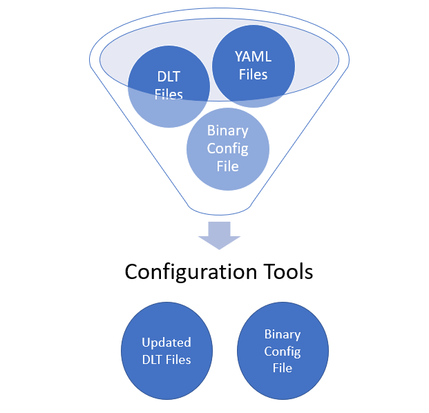
The configuration tool processes YAML and DLT files in the following way (note that binary itself can be used as input and output at the same time):
Therefore, this section introduces the configuration tool, which is located in the BootloaderCorePkg/Tools Directory. The most important is ConfigEditor.py, which is a graphical tool. After opening, it is as follows:
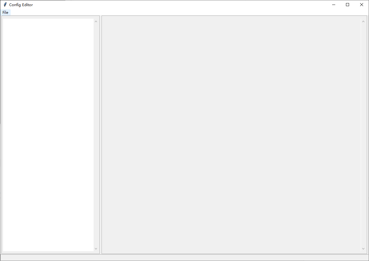
Click "File" and only "Open Config YAML file..." can be selected for the first time:
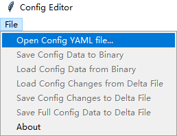
Here you can select the CfgDataDef.yaml mentioned earlier, that is, the basic configuration file. After that, you can select "Load Config Changes from Delta File" In this way, the newly added DLT file will overwrite the original display, and then you can continue to modify and finally save the modified data. Such data can be a DLT file that contains only the modified part, overwrite all configured DLT files, or directly generate binary files.
In addition to ConfigEditor.py, there is also a configuration tool that is used to convert YAML files into header files platform \ xxpkg \ include \ configdatastruct. H. It will be included in SBL code to finally obtain and use the configuration through the code.
The use process of the final configuration tool is as shown in the figure below:
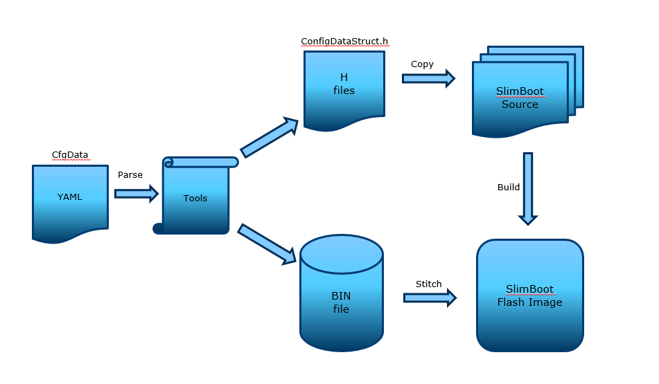
Generally speaking, SBL configuration is the basic configuration defined by YAML file. The DLT file modifies the configuration according to the actual board and finally generates a binary configuration file. This binary configuration file will be put into the SBL binary for subsequent acquisition. In the SBL code, the current PlatformId will be judged and the required binary configuration file will be loaded to complete the final configuration.
Finally, even if the SBL binary is generated, its parameters can still be modified through the tool, which is post build customization.