characteristic
MPU6050 can simultaneously detect three-axis acceleration, motion data of three-axis gyroscope (three-axis angular velocity) and temperature data. Using its internal DMP module (Digital Motion Processor), the sensor data can be filtered and fused, and the attitude calculated data can be output directly to the main controller through the IIC interface, so as to reduce the amount of calculation of the main controller. The attitude calculation frequency can reach up to 200Hz
| parameter | explain |
|---|---|
| power supply | 3.3V-5V |
| communication interface | IIC protocol, the maximum frequency of IIC clock supported is 400KHz |
| Measurement dimension | Acceleration: 3D gyroscope: 3D |
| ADC resolution | Acceleration: 16 bit gyroscope: 16 bit |
| Acceleration measurement range | ± 2g, ± 4g, ± 8g, ± 16g, where G is the gravitational acceleration constant, g=9.8m/s ² |
| Maximum acceleration resolution | 16384 LSB/g |
| Acceleration measurement accuracy | 0.1g |
| Acceleration output frequency | Up to 1000Hz |
| Gyroscope measurement range | ±250 º/s , ±500 º/s , ±1000 º/s, ±2000 º/s, |
| Gyroscope maximum resolution | 131 LSB/( º/s) |
| Gyroscope measurement accuracy | 0.1 º/s |
| Gyro output frequency | Up to 8000Hz |
| DMP attitude solution frequency | Up to 200Hz |
| Measuring range of temperature sensor | -40~ +85℃ |
| Temperature sensor resolution | 340 LSB/℃ |
| Temperature sensor accuracy | ±1℃ |
| working temperature | -40~ +85℃ |
| power waste | 500uA~3.9mA (working voltage 3.3V) |
Pin description
| Pin name | explain |
|---|---|
| VCC | 3.3/5V power input |
| GND | Ground wire |
| SCL | I2C from the clock signal line SCL (pull-up resistor connected to the module) |
| SDA | I2C from data signal line SDA (pull-up resistor connected to module) |
| XDA | I2C main serial data signal line, used for external sensor (pull-up resistance has been connected to the module) |
| XCL | I2C main serial clock signal line, used for external sensor (pull-up resistor has been connected to the module) |
| AD0 | When the slave address setting pin is grounded or suspended, the address is 0x68; When connected to VCC, the address is 0x69 |
| INT | Interrupt output pin |
Remarks: SDA/SCL and XDA/XCL communication pins are two groups of I2C signal lines respectively; When the module communicates with the external host, SDA/SCL is used, such as communicating with STM32 chip; XDA/XCL is used when MPU6050 chip communicates with other I2C sensors, but it is generally not used in this way.
The module pin is connected with the single chip microcomputer
| Pin name | Development board connection |
|---|---|
| VCC | Connected to 3.3 or 5V |
| GND | GND |
| SCL | PB6 |
| SDL | PB7 |
| AD0 | Suspended or grounded |
| INT | PA11 |
Programming points
(1) Initialize I2C of STM32 (software simulation);
(2) Write control parameters to MPU6050 using I2C;
(3) Regularly read acceleration, angular velocity and temperature data;
Use I2C software to drive mpu6050
#define GPIO_PORT_I2C 	 GPIOB 			/*  GPIO port*/
#define RCC_I2C_PORT  	 RCC_APB2Periph_GPIOB 		/*  GPIO clock*/
#define I2C_SCL_PIN 		 GPIO_ Pin_ six 			/*  GPIO connected to SCL*/
#define I2C_SDA_PIN 		 GPIO_ Pin_ seven 			/*  GPIO connected to SDL*/

#define I2C_SCL_1()  GPIO_SetBits(GPIO_PORT_I2C, I2C_SCL_PIN)		/* SCL = 1 */
#define I2C_SCL_0()  GPIO_ResetBits(GPIO_PORT_I2C, I2C_SCL_PIN)		/* SCL = 0 */

#define I2C_SDA_1()  GPIO_SetBits(GPIO_PORT_I2C, I2C_SDA_PIN)		/* SDA = 1 */
#define I2C_SDA_0()  GPIO_ResetBits(GPIO_PORT_I2C, I2C_SDA_PIN)		/* SDA = 0 */

#define I2C_SDA_READ()  GPIO_ReadInputDataBit(GPIO_PORT_I2C, I2C_SDA_PIN) 	/* Read SDA data*/

static void i2c_Delay(void)
{
	uint8_t i;
	for (i = 0; i < 10; i++);
}

//When SCL is at high level, SDA has a next skip edge, indicating I2C bus start signal
void i2c_Start(void)
{
    /*    _____
     *SDA      \_____________
     *    __________
     *SCL           \________
     */
	I2C_SDA_1();
	I2C_SCL_1();
	i2c_Delay();
	I2C_SDA_0();
	i2c_Delay();
	I2C_SCL_0();
	i2c_Delay();
}

//When SCL is at high level, SDA has an up skip edge indicating I2C bus stop signal
void i2c_Stop(void)
{
    /*               _______
     *SDA __________/
     *          ____________
     *SCL _____/
     */
	I2C_SDA_0();
	I2C_SCL_1();
	i2c_Delay();
	I2C_SDA_1();
}

/*CPU Send 8bit data to I2C bus equipment

*/
void i2c_SendByte(uint8_t _ucByte)
{
	uint8_t i;

	/* Send the upper 7 bits first,*/
	for (i = 0; i < 8; i++)
	{
		if (_ucByte & 0x80)
		{
			I2C_SDA_1();//Sent 1
		}
		else
		{
			I2C_SDA_0();//Sent 0
		}
		i2c_Delay();
		I2C_SCL_1();
		i2c_Delay();
		I2C_SCL_0();
		if (i == 7)
		{
			 I2C_SDA_1(); //Release bus
		}
		_ucByte <<= 1;	/*Shift left one bit */
		i2c_Delay();
	}
}

/*
CPU Read 8bit data from I2C device
*/
uint8_t i2c_ReadByte(u8 ack)
{
	uint8_t i;
	uint8_t value;

	/* The first bit read is bit7 of data */
	value = 0;
	for (i = 0; i < 8; i++)
	{
		value <<= 1;
		I2C_SCL_1();
		i2c_Delay();
		if (I2C_SDA_READ())
		{
			value++;
		}
		I2C_SCL_0();
		i2c_Delay();
	}
	if(ack==0)
		i2c_NAck();
	else
		i2c_Ack();
	return value;
}

/*
CPU Generate a clock and read the ACK response signal of the device
*/
uint8_t i2c_WaitAck(void)
{
	uint8_t re;

	I2C_SDA_1();	/* CPU Release SDA bus */
	i2c_Delay();
	I2C_SCL_1();	/* CPU Drive SCL = 1, this device will return ACK response */
	i2c_Delay();
	if (I2C_SDA_READ())	/* CPU Read SDA port status */
	{
		re = 1;
	}
	else
	{
		re = 0;
	}
	I2C_SCL_0();
	i2c_Delay();
	return re;
}

/*
CPU Generate an ACK signal

*/
void i2c_Ack(void)
{

    /*           ____
     *SCL ______/    \______
     *    ____         _____
     *SDA     \_______/
     */
	I2C_SDA_0();	/* CPU Drive SDA = 0 */
	i2c_Delay();
	I2C_SCL_1();	/* CPU Generate 1 clock */
	i2c_Delay();
	I2C_SCL_0();
	i2c_Delay();
	I2C_SDA_1();	/* CPU Release SDA bus */
}

/*
CPU Generate 1 NACK signal
*/
void i2c_NAck(void)
{
    /*           ____
     *SCL ______/    \______
     *    __________________
     *SDA
     */
	I2C_SDA_1();	/* CPU Drive SDA = 1 */
	i2c_Delay();
	I2C_SCL_1();	/* CPU Generate a clock */
	i2c_Delay();
	I2C_SCL_0();
	i2c_Delay();
}

/*
Configure GPIO of I2C bus
*/
void i2c_GPIO_Config(void)
{
	GPIO_InitTypeDef GPIO_InitStructure;

	RCC_APB2PeriphClockCmd(RCC_I2C_PORT, ENABLE);	//Clock

	GPIO_InitStructure.GPIO_Pin = I2C_SCL_PIN | I2C_SDA_PIN;
	GPIO_InitStructure.GPIO_Speed = GPIO_Speed_50MHz;
	GPIO_InitStructure.GPIO_Mode = GPIO_Mode_Out_OD; //Open drain output
	GPIO_Init(GPIO_PORT_I2C, &GPIO_InitStructure);

	//Stop the signal and reset all devices on the I2C bus
	i2c_Stop();
}

/*
CPU Send the device address, and then read the device response whether there is a device
*/
uint8_t i2c_CheckDevice(uint8_t _Address)
{
	uint8_t ucAck;

	i2c_GPIO_Config();		/* Configure GPIO */

	i2c_Start();		/*I2C Start signal*/

	/* Transmitting device address and read-write control bit (0 = write, 1 = read) bit7 bits are transmitted first */
	i2c_SendByte(_Address|I2C_WR);
	ucAck = i2c_WaitAck();	/*Test equipment response */

	i2c_Stop();			/* I2C End signal */

	return ucAck;
}
mp6050 uses software I2C to read and write data
write
void MPU6050_WriteReg(u8 reg_add,u8 reg_dat)
{
	i2c_Start();
	i2c_SendByte(MPU6050_SLAVE_ADDRESS);
	i2c_WaitAck();
	i2c_SendByte(reg_add);
	i2c_WaitAck();
	i2c_SendByte(reg_dat);
	i2c_WaitAck();
	i2c_Stop();
}
read
void MPU6050_ReadData(u8 reg_add,unsigned char*Read,u8 num)
{
	unsigned char i;

	i2c_Start();
	i2c_SendByte(MPU6050_SLAVE_ADDRESS);
	i2c_WaitAck();
	i2c_SendByte(reg_add);
	i2c_WaitAck();

	i2c_Start();
	i2c_SendByte(MPU6050_SLAVE_ADDRESS+1);
	i2c_WaitAck();

	for(i=0;i<(num-1);i++){
		*Read=i2c_ReadByte(1);
		Read++;
	}
	*Read=i2c_ReadByte(0);
	i2c_Stop();
}
Register description in manual
1. Power management register
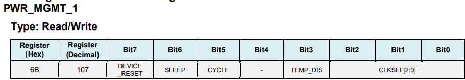
Description: this register allows the user to configure the power mode and clock source. It also provides a 1-bit reset of the entire device, and a 1-bit enable temperature sensor
When SLEEP is set to 1, the device enters the low-power SLEEP mode; TEMP_DIS is used to set whether the temperature sensor is enabled, and 0 is enabled
CLKSEL[2:0] clock source is as follows:,

The accuracy of internal 8M RC crystal oscillator is not high. Generally, X/Y/Z-axis gyro is selected as the clock source of reference PLL, and CLKSEL=001 is set
2. Gyro register
This register is used to trigger the gyro self-test and configure the range of the gyro.
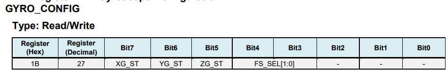
FS_ Value of sel [1:0]: 0, ± 250 ° / S; 1,±500° /S; 2,±1000° /S; 3,±2000° /S;
It is generally set to 3, ± 2000dps. Because the ADC of the gyroscope is 16 bit resolution, the sensitivity is 65536/4000 = 16.4LSB(° / S)
3. Acceleration sensor
This register is used to trigger the accelerometer self-test and configure the accelerometer full-scale range. The register is also configured with a digital high pass filter (DHPF).
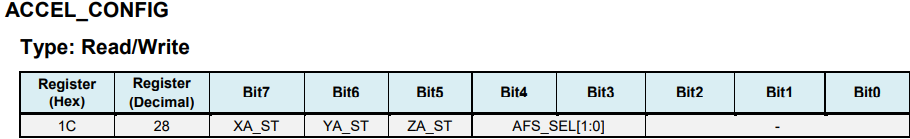
AFS_SEL[1:0] selection range: 0, ± 2g; 1,±4g; 2,±8g; 3,±16g;
It is generally set to 0, ± 2g, and the sensitivity is 65536/4=16384 LSB/g
4. Sampling rate
This register specifies the divider of the gyro output rate used to generate the MPU-60X0 sampling rate.

The sensor register output, FIFO output and DMP sampling are based on the sampling rate.
Here, the output frequency of the gyroscope is 1Khz or 8Khz, which is related to the setting of digital low-pass filter (DLPF).
Formula: sampling frequency = gyro output frequency / (1+SMPLRT_DIV)
When DLPF_ When CFG = 0 / 7, the frequency is 8Khz and 1Khz in other cases. Moreover, the DLPF filtering frequency is generally set
Is half the sampling rate.
For example, if the sampling rate is assumed to be 125HZ, then SMPLRT_DIV=1000/125 - 1 = 7
5. Configuration register
This register configures the external frame synchronization (FSYNC) pin sampling and digital low-pass filter (DLPF) settings of gyroscope and accelerometer.
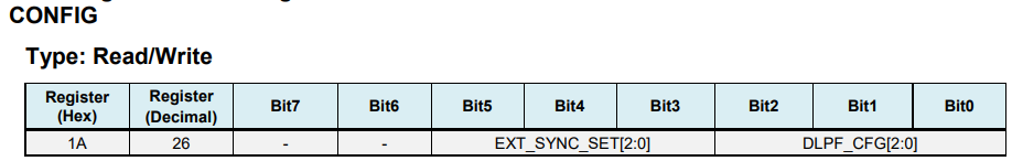
Among them, DLPF_CFG is configured with low-pass filtering as follows
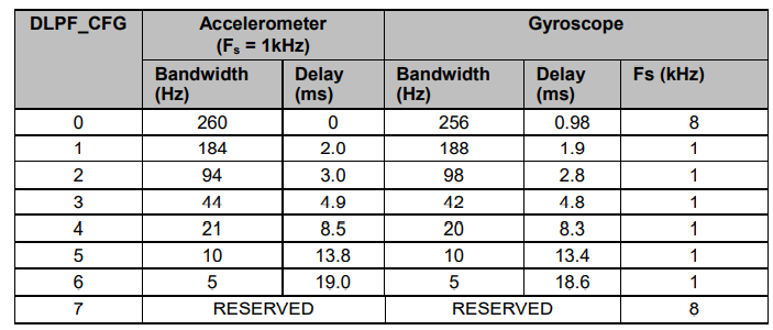
Generally, we set the bandwidth of the angular velocity sensor to half of its sampling rate. As mentioned earlier, if the sampling rate is set to 125Hz, the bandwidth should be set to 62Hz. If the approximate value is 44Hz, the DLPF should be set_ CFG=011
Steps for MPU6050 initialization:
- Reset MPU6050 to restore all internal registers of MPU6050 to default values
The register bit 0x00 must be set to wake up MPU6050 and enter the normal working state. Generally, X-axis gyro PLL is selected as the clock source to obtain a higher precision clock. - Gyro configuration register (0x1B)
- Accelerometer configuration register (0x1C)
- The sampling rate of the gyroscope is controlled by the sampling rate frequency division register (0x19);
- Set the digital low-pass filter, which is controlled by the configuration register (0x1A);
DLPF bit setting, i.e. DLPF_CFG[2:0], acceleration technology and gyroscope are filtered according to the configuration of these three bits,
Initialization program
#define MPU6050_RA_SMPLRT_DIV       0x19
#define MPU6050_RA_CONFIG           0x1A
#define MPU6050_RA_GYRO_CONFIG      0x1B
#define MPU6050_RA_ACCEL_CONFIG     0x1C

#define MPU6050_RA_PWR_MGMT_1       0x6B
#define MPU6050_RA_PWR_MGMT_2       0x6C

#define MPU6050_WHO_AM_I        0x75
#define MPU6050_SMPLRT_DIV      0  //8000Hz  fix me
#define MPU6050_DLPF_CFG        0  //fix me
#define MPU6050_ GYRO_ Out 0x43 / / mpu6050 gyro data register address
#define MPU6050_ ACC_ Out 0x3b / / mpu6050 acceleration data register address

void MPU6050_Init(void)
{
  int i=0,j=0;
  for(i=0;i<1000;i++)
  {
    for(j=0;j<1000;j++);
  }
	MPU6050_WriteReg(MPU6050_RA_PWR_MGMT_1, 0x01);
	MPU6050_WriteReg(MPU6050_RA_SMPLRT_DIV , 0x07);	//Worth setting
	MPU6050_WriteReg(MPU6050_RA_CONFIG , 0x03);//Worth setting
	MPU6050_WriteReg(MPU6050_RA_ACCEL_CONFIG , 0x00);
	MPU6050_WriteReg(MPU6050_RA_GYRO_CONFIG, 0x18);
}
data fetch
1. Gyro data output register
By reading these six registers, you can read the value of the x/y/z axis of the gyroscope. For example, the data of the X axis can be obtained by reading the 0X43 (high 8 bits) and 0X44 (low 8 bits) registers, and so on for other axes
void MPU6050ReadGyro(short *gyroData)
{
    u8 buf[6];
    MPU6050_ReadData(MPU6050_GYRO_OUT,buf,6);
    gyroData[0] = (buf[0] << 8) | buf[1];
    gyroData[1] = (buf[2] << 8) | buf[3];
    gyroData[2] = (buf[4] << 8) | buf[5];
}
2. Accelerometer data output register
By reading these six registers, you can read the value of the x/y/z axis of the acceleration sensor. For example, reading the data of the X axis can be obtained by reading the 0X3B (high 8 bits) and 0X3C (low 8 bits) registers, and so on for other axes
void MPU6050ReadAcc(short *accData)
{
    u8 buf[6];
    MPU6050_ReadData(MPU6050_ACC_OUT, buf, 6);
    accData[0] = (buf[0] << 8) | buf[1];
    accData[1] = (buf[2] << 8) | buf[3];
    accData[2] = (buf[4] << 8) | buf[5];
}
3. Temperature conversion
The value of the temperature sensor can be obtained by reading the 0X41 (high 8 bits) and 0X42 (low 8 bits) registers,
The temperature conversion formula is: Temperature = 36.53 + regval/340
Where, Temperature is the calculated Temperature value, in ° C, and regval is the Temperature sensor value read from 0X41 and 0X42
void MPU6050_ReturnTemp(float *Temperature)
{
	short temp3;
	u8 buf[2];

	MPU6050_ReadData(MPU6050_RA_TEMP_OUT_H,buf,2);
    temp3= (buf[0] << 8) | buf[1];
	*Temperature=((double) temp3/340.0)+36.53;
}
4. Main program
int main(void)
{
	short Accel[3];
	short Gyro[3];
	float Temp;
	SysTick_Init();
	SysTick->CTRL|=SysTick_CTRL_ENABLE_Msk;
	USART_Config();
	i2c_GPIO_Config();
	MPU6050_Init();

	//Detect MPU6050
	if (MPU6050ReadID() == 1)
	{
		while(1)
		{
			if(Task_Delay[0]==TASK_ENABLE)
			{
				Task_Delay[0]=1000;
			}
			if(Task_Delay[1]==0)
			{
				MPU6050ReadAcc(Accel);
				printf("\acceleration %8d%8d%8d    ",Accel[0],Accel[1],Accel[2]);
				MPU6050ReadGyro(Gyro);
				printf("gyroscope %8d%8d%8d    ",Gyro[0],Gyro[1],Gyro[2]);
				MPU6050_ReturnTemp(&Temp);
				printf("temperature %8.2f",Temp);
				Task_Delay[1]=500;//Frequency of updating data
			}
		}
	}
}
mpu6050 output value
Acceleration: 2634 - 2146 16238 gyroscope: - 63 - 29 - 33 temperature: 21.51
Acceleration: 2680 - 2312 16044 gyroscope: - 53 - 18 - 36 temperature: 21.53
Acceleration: 2744 - 2320 16196 gyroscope: - 48 - 16 - 36 temperature: 21.66
Acceleration: - 1 - 1 - 1 gyroscope: - 1 - 1 - 1 temperature: 36.53
Acceleration: - 1 - 1 - 1 gyroscope: - 1 - 1 - 1 temperature: 36.53
Acceleration: - 9586 3804 12182 gyroscope: - 456 - 594 - 72 temperature: 22.14
Acceleration: - 2452 - 1740 15716 gyroscope: - 232 - 436 - 169 temperature: 22.17
Acceleration: - 986 - 1736 16178 gyroscope: - 64 - 184 - 56 temperature: 22.20
Acceleration: - 194 - 1790 16366 gyroscope: - 46 - 9 - 11 temperature: 22.24