In the previous experiment, we lit the LED and buzzer respectively. These two devices use the output function of GPIO. Next, we will use the key to do the input function of the test board.
Hardware principle
Or check the backplane schematic,

There are two buttons on the development board, including ON_OFF is to restart the system. We don't need to consider KEY0. When the key is pressed, IO is grounded through KEY0 and pulled down. By default, it is pulled up through 10K resistance. Look at the whereabouts of KEY0
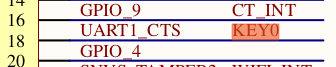
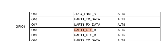
KEY_0 is connected to UART1_CTS, query manual, reuse as GPIO1_IO18.
The IO initialization process is similar to the configuration of the previous output application method. First, reuse settings, followed by electrical properties. Note that the input and output bottom values are different. If the input is 0, the 17th bit is set to 0 (0 is output and 1 is input)
void key_init(void)
{
    //GPIO Reuse initialization, reuse as GPIO5_IO01
    IOMUXC_SetPinMux(IOMUXC_UART1_CTS_B_GPIO1_IO18,0);
    /*
    Configure uart1_ CTS_ Electrical properties of B
    *bit 16:0 HYS close
    *bit [15:14]: 11 Default 22K pull-up
    *bit [13]: 1 pull function
    *bit [12]: 1 pull/keeper Enable
    *bit [11]: 0 Turn off the open circuit output
    *bit [7:6]: 10 Speed 100Mhz
    *bit [5:3]: 000 Close output
    *bit [0]: 0 Low conversion rate
     */
    IOMUXC_SetPinConfig(IOMUXC_UART1_CTS_B_GPIO1_IO18,0xF080);
    //Bit 18 is set as input
    GPIO1->GDIR &= ~(1<<18);
}
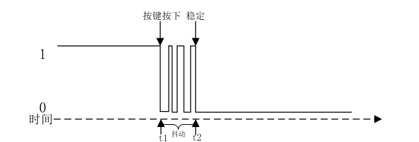
The DR register of GPIO is the external high and low level when IO is input. Read the bit corresponding to this register to know the high and low level status of the pin. After defining the data reading function, a function should be added to eliminate the effect of key jitter.
// Read key value: 0 means pressed, 1 means not pressed
int read_key(void)
{
    int ret = 0;
    ret = GPIO1->DR >> 18 & 0x1;
    return ret;
}

//Eliminate key jitter: delay 10 ms
int key_getvalue(void)
{
    int ret = 0;
    static unsigned char release = 1;  //Record whether the key is released: 1 is released
    if((release == 1) && (read_key() == 0)) //When pressed
    {   release = 0;                    // Mark as key press
        delay(10);
        release = 0;
        if(read_key()==0)   //Delay 10 ms Press it later and it is determined to be valid
            {
                ret = KEY0_VALUE;
            }
    }
    else if(read_key() == 1) //Not pressed
        {
            ret = KEY_NONE;
            release = 1;   //Mark key release
        }
    return ret;
}
When reading the IO status, the function to eliminate jitter is called. The delay in the function is 10ms. If the status is still pressed after 10ms, the response is to press the key to prevent jitter during key jitter
Whole BSP_ The key folder is as follows
Header file
#ifndef __BSP_KEY_H
#define __BSP_KEY_H

#include "imx6ul.h"

/*Enumeration type describes GPIO direction*/
typedef enum _gpio_pin_direction
{
    kGPIO_DigitalInput = 0U,
    kGPIO_DigitaoOutput = 1U
}_gpio_pin_direction_t;

typedef struct gpio_pin_config
{
    _gpio_pin_direction_t direction;
    uint8_t outputLogic;
}gpio_pin_config;

/*Key value*/
enum keyvalue{
    KEY_NONE = 0, //No press is 0
    KEY0_VALUE,
};


void gpio_init(GPIO_Type *base,int pin,gpio_pin_config *config);
int gpio_pinread(GPIO_Type *base,int pin);
void gpio_pinwrite(GPIO_Type *base,int pin,int value);

#endif
The header file defines an enumeration type corresponding to the key value of each key
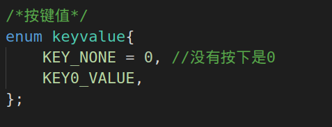
KEY0_NONE means no key is pressed, KEY0_VALUE means that the first button is pressed. This is not mentioned in the whole demonstration process, and the key response is directly assigned.
#include "bsp_key.h"
#include "bsp_delay.h"
// Initialization key
void key_init(void)
{
    //GPIO Reuse initialization, reuse as GPIO5_IO01
    IOMUXC_SetPinMux(IOMUXC_UART1_CTS_B_GPIO1_IO18,0);
    IOMUXC_SetPinConfig(IOMUXC_UART1_CTS_B_GPIO1_IO18,0xF080);
    //Bit 18 is set as input
    GPIO1->GDIR &= ~(1<<18);
}

// Read the key value. 0 means pressed and 1 means not pressed
int read_key(void)
{
    int ret = 0;
    ret = GPIO1->DR >> 18 & 0x1;
    return ret;
}

//Eliminate key jitter: delay 10 ms
int key_getvalue(void)
{
    int ret = 0;
    static unsigned char release = 1;  //Record whether the key is released: 1 is released
    if((release == 1) && (read_key() == 0)) //When pressed
    {   release = 0;                    // Mark as key press
        delay(10);
        release = 0;
        if(read_key()==0)   //Delay 10 ms Press it later and it is determined to be valid
            {
                ret = KEY0_VALUE;
            }
    }
    else if(read_key() == 1) //Not pressed
        {
            ret = KEY_NONE;
            release = 1;   //Mark key release
        }
    return ret;
}
Key use
Three peripherals are used:
- KEY0
- LED0
- Buzzer
The LED keeps flashing, indicating that the program is running all the time. Press KEY0 to switch the working state of the buzzer. main function of direct code
int main(void)
{
    unsigned char led_state = OFF;
    unsigned char beep_state = OFF;
    int i = 0;
    int key_value;
    clk_enable();
    led_init();
    beep_init();
    key_init();

    while(1)
    {   key_value = key_getvalue();
        if(key_value == KEY0_VALUE) //Press the key
        {
            switch (key_value)
            {
                case KEY0_VALUE:
                    beep_state = !beep_state;
                    beep_switch(beep_state);
                    break;
            }
        }
        i++;
        if(i == 50)
        {
            i = 0;
            led_state = !led_state;
            led_switch(LED0,led_state);
        }
        delay(10);
    }
    return 0;
}
The whole process is to initialize the clock and peripherals. The light flashes all the time in the main cycle and scans KEY0. When the key is pressed, the working state of the buzzer is changed. Pay attention to adding paths when making!
General GPIO driver
After completing the input and output test of GPIO, you can summarize and write a general GPIO driver!
The header file defines the data types to be used and also declares the interface functions
#ifndef __BSP_GPIO_H
#define __BSP_GPIO_H

#include "imx6ul.h"

/*Enumeration type describes GPIO direction*/
typedef enum _gpio_pin_direction
{
    kGPIO_DigitalInput = 0U,
    kGPIO_DigitalOutput = 1U,
} gpio_pin_direction_t;

typedef struct _gpio_pin_config
{
    gpio_pin_direction_t direction;
    uint8_t outputLogic;
} gpio_pin_config_t;


void gpio_init(GPIO_Type *base, int pin, gpio_pin_config_t *config);
int gpio_pinread(GPIO_Type *base, int pin);
void gpio_pinwrite(GPIO_Type *base, int pin, int value);

#endif
Note that the defined structure gpio_pin_config_t. There are two parameters. One is the direction of GPIO, which corresponds to the above enumeration type gpio_pin_direction_t. Enumeration values go in and out one by one. There is also a default value, which is not useful for input. You can set the initial value for output.
The C code is the same as all the previous drivers. First, it is an initialization, and then there is a read-write function that defines the data.
#include "bsp_gpio.h"

void gpio_init(GPIO_Type *base,
                int pin,
                gpio_pin_config_t *config)
{
    if(config->direction == kGPIO_DigitalInput) //gpio For input
    {
        base->GDIR &= ~(1 << pin);
    }
    //gpio For output
    else
    {
        base->GDIR |= 1<<pin;
        //Set default level
        gpio_pinwrite(base,pin,config->outputLogic);
    }
}

/*
Read GPIO specified pin
*/
int gpio_pinread(GPIO_Type *base,int pin)
{
    return (((base->DR >> pin)) &0x1);
}

/*
Write GPIO specified pin
*/
void gpio_pinwrite(GPIO_Type *base,int pin,int value)
{
    if (value == 0U)
    {
        base->DR &= ~(1U << pin);
    }
    else
    {
        base->DR |= (1U<<pin);
    }
}
In the initialization function, we use two pointers (base and config), and base corresponds to GPIO_Type

When you operate on that register, you can reference it directly,
config is the data type defined in the header file mentioned earlier. It has an initial value in one direction. First define the input and output (GDIR) and determine whether it is output according to the defined initial value.
Reading and writing is to directly operate the bit corresponding to Dr according to the defined Pin value. When reading, take out the data in DR and move it to the right, and perform the sum operation between the value corresponding to pin and 0x1 (clear the others, and only keep the value of 1 bit); The write function is to move 1 to the bit corresponding to pin to the left. If you write 0, it is to take the inverse and Dr and, set bit to 0, and vice versa.
Use of gpio universal driver (input)
When the general driver is written, it can be used. We put the previous bsp_key to modify
#include "bsp_key.h"
#include "bsp_gpio.h"
#include "bsp_delay.h"


// Initialization key
void key_init(void)
{
    //GPIO Reuse initialization, reuse as GPIO5_IO01
    //Bit 18 is set as input

    IOMUXC_SetPinMux(IOMUXC_UART1_CTS_B_GPIO1_IO18,0);
    IOMUXC_SetPinConfig(IOMUXC_UART1_CTS_B_GPIO1_IO18,0xF080);

    gpio_pin_config_t key_config;

    key_config.direction = kGPIO_DigitalInput;
    gpio_init(GPIO1,18,&key_config);


}

//Eliminate key jitter: delay 10 ms
int key_getvalue(void)
{
    int ret = 0;
    int _get_data = gpio_pinread(GPIO1,18);
    static unsigned char release = 1;  //Record whether the key is released: 1 is released
    if((release == 1) && (_get_data == 0)) //When pressed
    {   release = 0;                    // Mark as key press
        delay(10);
        release = 0;
        if(_get_data == 0)   //Delay 10 ms Press it later and it is determined to be valid
            {
                ret = KEY0_VALUE;
            }
    }
    else if(_get_data == 1) //Not pressed
        {
            ret = KEY_NONE;
            release = 1;   //Mark key release
        }
    return ret;
}
Because you can directly call the function to read IO, a read is omitted here_ Key(), be sure to call GPIO when using it_ Init() passes parameters by reference.
There is also the key defined during initialization_ Config is a structure, which should be used Points to its internal members, and the corresponding structure pointer adopts the - > method, that is
- A *p: P - > play(); On the left is the structure pointer.
- A p: P. pay (); On the left are structural variables.
The function read later is very simple and has nothing to say!
Use of gpio universal driver (output)
According to the previous code, you can modify the LED lighting code to see how to use this general driver!
#include "bsp_led.h"
#include "bsp_gpio.h"

/*Initialize LED*/
void led_init(void)
{
    // Reuse, electrical attribute register initialization

    IOMUXC_SetPinMux(IOMUXC_GPIO1_IO03_GPIO1_IO03,0);
    IOMUXC_SetPinConfig(IOMUXC_GPIO1_IO03_GPIO1_IO03,0x10B0);
    // GPIO1 Direction register,
    // GPIO1->GDIR = 0x8;

    gpio_pin_config_t gpio_config;

    gpio_config.direction = kGPIO_DigitalOutput;
    gpio_config.outputLogic = 0U;

    gpio_init(GPIO1,3,&gpio_config);
}


// Light up LED
void led_on(void)
{
    // GPIO1->DR &= ~(1<<3); //bit3 Clear
    gpio_pinwrite(GPIO1,3,0U);

}

// close LED
void led_off(void)
{
    // GPIO1->DR |=(1<<3);  //bit3 Set one
    gpio_pinwrite(GPIO1,3,1U);
}


void led_switch(int led, int status)
{
    switch(led)
    {
        case LED0:
            if(status == ON)
                gpio_pinwrite(GPIO1,3,0U);
            else if(status == OFF)
                gpio_pinwrite(GPIO1,3,1U);
            break;
    }
}
The initialization process is almost the same. Compare it with the previous one to know what the idea is!