Vulkan's inherent functions
Vulkan's inherent functionality, early graphics API s provided default state in many stages of a graphics rendering pipeline. In Vulkan, from the size of the viewport to the color mixing function, you need to do everything by yourself. In this chapter we will fill in all the structures related to the operation of inherent functions.
1, Vertex input
The VkPipelineVertexInputStateCreateInfo structure describes the format of vertex data, which is passed to the vertex shader. It is described in two ways:
1.Bindings: determine whether the data is each vertex or each instance (instance) according to the data gap
 2.Attribute description: describes the relevant attribute types in the vertex shader to be bound and loaded.
Because we hardcode vertex data into vertex shader, the structure we are going to fill has no vertex data to load. We will return to the chapter "vertex buffer".
VkPipelineVertexInputStateCreateInfo vertexInputInfo = {};
vertexInputInfo.sType = VK_STRUCTURE_TYPE_PIPELINE_VERTEX_INPUT_STATE_CREATE_INFO;
vertexInputInfo.vertexBindingDescriptionCount = 0;
vertexInputInfo.pVertexBindingDescriptions = nullptr; // Optional
vertexInputInfo.vertexAttributeDescriptionCount = 0;
vertexInputInfo.pVertexAttributeDescriptions = nullptr; // Optional
The pVertexBindingDescriptions and pvertexattributeddescriptions members point to the structure array to further describe the loaded vertex data information. Add the structure after the shaderstage array in the createGraphicsPipeline function.
2, Input components
The VkPipelineInputAssemblyStateCreateInfo structure describes two things: what type of geometry topology the vertex data is drawn with and whether vertex rope restart is enabled. The enumeration values of topology types of entities are as follows:
VK? Primitive? Topology? Point? List: vertex to point
 VK? Primary? Topology? Line? List: two points form a line, and vertices are not shared
 VK? Primary? Topology? Line? Strip: two points form a line, and the end vertex of each line segment is the start vertex of the next line segment
 VK? Primitive? Topology? Triangle? List: three points form a face, and vertices are not shared
 VK? Primary? Topology? Triangle? Strip: the second and third vertices of each but learned lesson are the first two vertices of the next triangle
Normally, the vertex data is indexed according to the sequence in the buffer, but the index of vertex data can also be specified by the element buffer buffer. Improve performance by reusing vertex data. If you set the primitiveRestartEnable member to VK? True, you can use 0xFFFF or 0xFFFFFF as a special index to decompose the entity topology of lines and triangles in? STRIP mode.
Through this tutorial, we draw triangles, so we insist on filling the data structure in the following format:
VkPipelineInputAssemblyStateCreateInfo inputAssembly = {};
inputAssembly.sType = VK_STRUCTURE_TYPE_PIPELINE_INPUT_ASSEMBLY_STATE_CREATE_INFO;
inputAssembly.topology = VK_PRIMITIVE_TOPOLOGY_TRIANGLE_LIST;
inputAssembly.primitiveRestartEnable = VK_FALSE;
3, Windows and clipping
The Viewport is used to describe the framebuffer as the target area of the rendering output. Its value is always set to (0, 0) and (width, height) in this tutorial.
VkViewport viewport = {};
viewport.x = 0.0f;
viewport.y = 0.0f;
viewport.width = (float) swapChainExtent.width;
viewport.height = (float) swapChainExtent.height;
viewport.minDepth = 0.0f;
viewport.maxDepth = 1.0f;
Remember that the swap chain and its images image size WIDTH and HEIGHT will vary depending on the form. Swap chain images will be used in framebuffers, so we should stick to their size.
The minDepth and maxDepth values specify the range of depths in the framebuffer. These values must converge to [0.0f, 1.0f] interval impulses, but minDepth may be greater than maxDepth. If you do not specify anything, the standard values of 0.0f and 1.0f are recommended.
viewports defines the conversion relationship between image image and framebuffer, and clipping rectangle defines which areas of pixels are stored. Any pixel outside the clipping giant will be discarded in the rasterization stage. They function more like filters than defining transformation relationships. The difference is shown in the figure below. It should be noted that the clipping rectangle on the left side is only one of the many possible representations when the image is larger than the viewport size.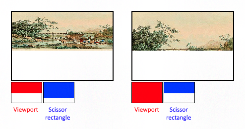
In this tutorial, we need to draw the image into the complete framebuffer, so we define a clipping rectangle to cover the whole image:
VkRect2D scissor = {};
scissor.offset = {0, 0};
scissor.extent = swapChainExtent;
viewport and clipping rectangle need to be combined with VkPipelineViewportStateCreateInfo structure. You can use multiple viewports and crop rectangles in some graphics cards, referenced through arrays. Using this feature requires GPU to support this function, which depends on the creation of logical devices.
VkPipelineViewportStateCreateInfo viewportState = {};
viewportState.sType = VK_STRUCTURE_TYPE_PIPELINE_VIEWPORT_STATE_CREATE_INFO;
viewportState.viewportCount = 1;
viewportState.pViewports = &viewport;
viewportState.scissorCount = 1;
viewportState.pScissors = &scissor;
4, Rasterization
Rasterization uses vertex shaders and specific geometric algorithms to shape vertices, and transfers the shape to fragment shaders for shading. It also performs depth testing, face cutting and clipping tests. It can configure the output slice elements and decide whether to output the entire element topology or border (wireframe rendering). All configurations are defined through the VkPipelineRasterizationStateCreateInfo structure.
VkPipelineRasterizationStateCreateInfo rasterizer = {};
rasterizer.sType = VK_STRUCTURE_TYPE_PIPELINE_RASTERIZATION_STATE_CREATE_INFO;
rasterizer.depthClampEnable = VK_FALSE;
Its depthclapenable is set to VK? True, and the elements beyond the far and near clipping faces will converge instead of discarding them. It's useful in special situations, like shadow maps. The use of this function requires the support of GPU.
rasterizer.rasterizerDiscardEnable = VK_FALSE;
If rasterizerdiscardanable is set to VK? True, geometry is never passed to the rasterization phase. This is the basic way to disable any output to the framebuffer.
rasterizer.polygonMode = VK_POLYGON_MODE_FILL;
polygonMode determines the content of the geometrically generated image. The following modes are valid:
VK? Polygon? Mode? Fill: polygon region fill
 VK? Polygon? Mode? Line: polygon edge wireframe drawing
 VK? Polygon? Mode? Point: polygon vertices are drawn as tracing points
The GPU function needs to be turned on to fill in any mode.
rasterizer.lineWidth = 1.0f;
The lineWidth member is directly populated, describing the width of the line based on the number of tiles. The maximum line width support depends on the hardware. Any line width greater than 1.0 needs to turn on the wideLines feature support of GPU.
rasterizer.cullMode = VK_CULL_MODE_BACK_BIT;
rasterizer.frontFace = VK_FRONT_FACE_CLOCKWISE;
The cullMode variable is used to determine the type of face clipping. You can disable culling, crop front faces, cull back faces, or all of them. frontFace is used to describe the order of vertices as front facing faces, which can be clockwise or counter clockwise.
rasterizer.depthBiasEnable = VK_FALSE;
rasterizer.depthBiasConstantFactor = 0.0f; // Optional
rasterizer.depthBiasClamp = 0.0f; // Optional
rasterizer.depthBiasSlopeFactor = 0.0f; // Optional
Rasterization can change the depth value by adding a constant or based on the slope of the slice element. Sometimes it's useful for shadow mapping, but we won't use it in the chapter. Set depthBiasEnable to VK? False.
5, Resampling
The VkPipelineMultisampleStateCreateInfo structure is used to configure multisampling. The so-called multiple sampling is an implementation of anti aliasing. It rasterizes to the same pixel by combining the fragment shader results of multiple polygons. This is mainly at the edge, where the most striking serrations appear. If only one polygon is mapped to a pixel, it does not need to run the fragment shader multiple times for sampling, which will cost less than high resolution. Enabling this function requires GPU support.
VkPipelineMultisampleStateCreateInfo multisampling = {};
multisampling.sType = VK_STRUCTURE_TYPE_PIPELINE_MULTISAMPLE_STATE_CREATE_INFO;
multisampling.sampleShadingEnable = VK_FALSE;
multisampling.rasterizationSamples = VK_SAMPLE_COUNT_1_BIT;
multisampling.minSampleShading = 1.0f; // Optional
multisampling.pSampleMask = nullptr; // Optional
multisampling.alphaToCoverageEnable = VK_FALSE; // Optional
multisampling.alphaToOneEnable = VK_FALSE; // Optional
We will not use multisampling in this tutorial, but we can try it at will. Please refer to the specification for specific parameters.
6, Depth and formwork testing
If you use depth or stencil buffers, you need to use the VkPipelineDepthStencilStateCreateInfo configuration. We don't need to use it now, so we simply pass nullptr, which is discussed in the deep buffer chapter.
7, Color blending
Clip shaders output specific colors that need to be mixed with colors already in framebuffer. This conversion process is called color mixing, which has two ways:
1. Mix old and new colors to produce a final color
 2. Use bitwise operation to mix old and new color values
There are two structures for configuring color blending. The first structure, VkPipelineColorBlendAttachmentState, includes each configuration attached to the framebuffer. The second structure, VkPipelineColorBlendStateCreateInfo, contains settings for global blending. In our example, only the first method is used:
VkPipelineColorBlendAttachmentState colorBlendAttachment = {};
colorBlendAttachment.colorWriteMask = VK_COLOR_COMPONENT_R_BIT | VK_COLOR_COMPONENT_G_BIT | VK_COLOR_COMPONENT_B_BIT | VK_COLOR_COMPONENT_A_BIT;
colorBlendAttachment.blendEnable = VK_FALSE;
colorBlendAttachment.srcColorBlendFactor = VK_BLEND_FACTOR_ONE; // Optional
colorBlendAttachment.dstColorBlendFactor = VK_BLEND_FACTOR_ZERO; // Optional
colorBlendAttachment.colorBlendOp = VK_BLEND_OP_ADD; // Optional
colorBlendAttachment.srcAlphaBlendFactor = VK_BLEND_FACTOR_ONE; // Optional
colorBlendAttachment.dstAlphaBlendFactor = VK_BLEND_FACTOR_ZERO; // Optional
colorBlendAttachment.alphaBlendOp = VK_BLEND_OP_ADD; // Optional
This way of configuring color mixing for each frame buffer is described by the following pseudo code:
if (blendEnable) {
    finalColor.rgb = (srcColorBlendFactor * newColor.rgb) <colorBlendOp> (dstColorBlendFactor * oldColor.rgb);
    finalColor.a = (srcAlphaBlendFactor * newColor.a) <alphaBlendOp> (dstAlphaBlendFactor * oldColor.a);
} else {
    finalColor = newColor;
}

finalColor = finalColor & colorWriteMask;
If blendEnable is set to VK? False, the new color output from the clip shader will not change, otherwise the two blending operations calculate the new color. The result is AND with colorWriteMask to determine the actual channel passed.
In most cases, the use of color blending is used to implement alpha blending, and the mixing of new and old colors will be based on their opacity transparent channel. finalColor as the final output:
finalColor.rgb = newAlpha * newColor + (1 - newAlpha) * oldColor;
finalColor.a = newAlpha.a;
This can be done with the following parameters:
colorBlendAttachment.blendEnable = VK_TRUE;
colorBlendAttachment.srcColorBlendFactor = VK_BLEND_FACTOR_SRC_ALPHA;
colorBlendAttachment.dstColorBlendFactor = VK_BLEND_FACTOR_ONE_MINUS_SRC_ALPHA;
colorBlendAttachment.colorBlendOp = VK_BLEND_OP_ADD;
colorBlendAttachment.srcAlphaBlendFactor = VK_BLEND_FACTOR_ONE;
colorBlendAttachment.dstAlphaBlendFactor = VK_BLEND_FACTOR_ZERO;
colorBlendAttachment.alphaBlendOp = VK_BLEND_OP_ADD;
All enumeration values for VkBlendFactor and VkBlendOp can be found in the specification.
The second structure holds references to all the framebuffers, which allows you to set a constant for the blending operation, which can be used as the blending factor for subsequent calculations:
VkPipelineColorBlendStateCreateInfo colorBlending = {};
colorBlending.sType = VK_STRUCTURE_TYPE_PIPELINE_COLOR_BLEND_STATE_CREATE_INFO;
colorBlending.logicOpEnable = VK_FALSE;
colorBlending.logicOp = VK_LOGIC_OP_COPY; // Optional
colorBlending.attachmentCount = 1;
colorBlending.pAttachments = &colorBlendAttachment;
colorBlending.blendConstants[0] = 0.0f; // Optional
colorBlending.blendConstants[1] = 0.0f; // Optional
colorBlending.blendConstants[2] = 0.0f; // Optional
colorBlending.blendConstants[3] = 0.0f; // Optional
If you need to use the second method to set the bitwise combination, you need to set logicOpEnable to VK? Ture. Binary bit operations are specified in the logicopf field. In the first mode, it will automatically disable, which is equivalent to turning off the mixing operation for each additional framebuffer, and blendEnable is VK? False. The colorWriteMask is used to determine which channel's color in the framebuffer is affected. It can also be disabled in two ways. Up to now, the color output from the clip buffer to the frame buffer has not changed.
8, Dynamic modification
Some of the previously created structures can be dynamically modified at run time without having to be recreated. For example, the size of the viewport, line width and blend constants. If you need to do this, you need to fill in the VkPipelineDynamicStateCreateInfo structure:
VkDynamicState dynamicStates[] = {
    VK_DYNAMIC_STATE_VIEWPORT,
    VK_DYNAMIC_STATE_LINE_WIDTH
};

VkPipelineDynamicStateCreateInfo dynamicState = {};
dynamicState.sType = VK_STRUCTURE_TYPE_PIPELINE_DYNAMIC_STATE_CREATE_INFO;
dynamicState.dynamicStateCount = 2;
dynamicState.pDynamicStates = dynamicStates;
This data is specified during the drawing process, which causes the previous relevant values to be ignored. We'll come back to that later in the chapter. If there is no value that needs to be modified dynamically, set it to nullptr.
9, Piping layout
You can use uniform in shaders, which is a global variable similar to dynamic state variables, which can be modified during painting, and you can change the behavior of shaders without having to recreate them. They are often used to pass the transform matrix to a vertex shader or to create a texture sampler at the clip shader's stroke.
These uniform values need to be specified through the VkPipelineLayout object during route creation. We still need to create an empty pipeline layout, even if it is used in subsequent content.
Create a class member variable to hold the object because we refer to it in the functions in the following chapters:
VkPipelineLayout pipelineLayout;
To create an object in the createGraphicsPipeline function:
VkPipelineLayoutCreateInfo pipelineLayoutInfo = {};
pipelineLayoutInfo.sType = VK_STRUCTURE_TYPE_PIPELINE_LAYOUT_CREATE_INFO;
pipelineLayoutInfo.setLayoutCount = 0; // Optional
pipelineLayoutInfo.pSetLayouts = nullptr; // Optional
pipelineLayoutInfo.pushConstantRangeCount = 0; // Optional
pipelineLayoutInfo.pPushConstantRanges = 0; // Optional

if (vkCreatePipelineLayout(device, &pipelineLayoutInfo, nullptr, &pipelineLayout) != VK_SUCCESS) {
    throw std::runtime_error("failed to create pipeline layout!");
}
The struct also specifies a push constant, which is a way to pass dynamic values to the shader. pipeline layout can be referenced throughout the life cycle of the program, so it is destroyed when the program exits.
void cleanup() {
    vkDestroyPipelineLayout(device, pipelineLayout, nullptr);
    ...
}
conclusion
This is all about fixed function. There seems to be a lot of work to do. Fortunately, we know almost all about rendering pipeline. This process reduces the possibility of unknown behavior at run time due to ignorance of the default state of some components.
However, before we can finally create a graphics pipeline, there is another object that needs to be created, which is render pass.

