First copy some of Du Niang's things:
In the microcomputer system composed of single chip microcomputer, the work of single chip microcomputer is often disturbed by external electromagnetic field, resulting in the running and flying of the program and falling into a dead cycle. The normal operation of the program is interrupted, and the system controlled by single chip microcomputer cannot continue to work, which will lead to the stagnation of the whole system and unpredictable consequences, Therefore, considering the real-time monitoring of the running state of single chip microcomputer, a module or chip specially used to monitor the running state of single chip microcomputer program is produced, commonly known as "watchdog".
In short, the watchdog is constantly monitoring our running program. We must "feed the dog" within the effective time of the specified time, so that the watchdog will know that our program is running normally. If our program runs away due to external reasons, it will not be able to feed the dog. Then the watchdog is unbearable due to hunger, He will reset our MCU in order to restart the program.
Watchdog is divided into independent watchdog and window watchdog. Independent watchdog is relatively simple. Of course, its security is not as high as window watchdog. IWDG is most suitable for those occasions where the watchdog is required to work completely independently outside the main program and has low requirements for time accuracy. WWDG is best suited for applications that require the watchdog to function in a precise timing window.
1, Independent watchdog (IWDOG)
-
IWDG introduction:
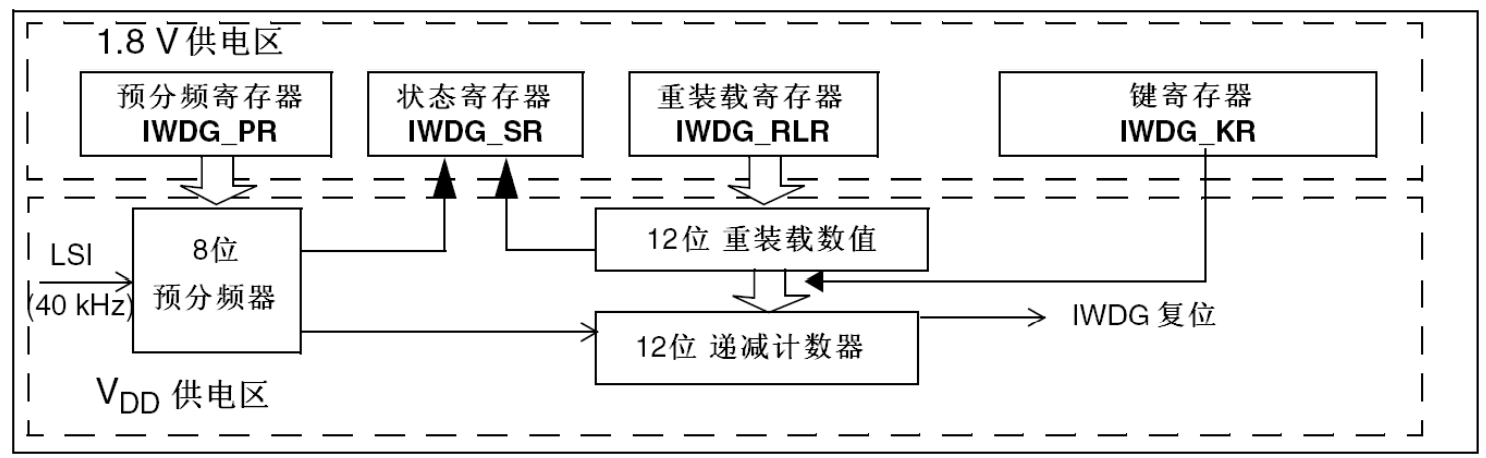
The independent watchdog is a 12 bit decrement counter in popular terms. When the value of the counter decreases from a certain value to 0, the system will generate a reset signal, i.e. IWDG_RESET. If the counter value is refreshed before the count is reduced to 0, the reset signal will not be generated. This action is what we often call feeding the dog. The watchdog function is powered by VDD voltage domain and can still work in stop mode and standby mode. -
Analysis of IWDG functional block diagram
-
LSI independent watchdog clock:
The clock of the independent watchdog is provided by the independent RC oscillator LSI. Even if the master clock fails, it is still effective and very independent. The frequency of LSI is generally between 30~60KHZ, and there will be a certain drift according to the temperature and workplace. We generally take 40KHZ, so the timing time of independent watchdog must be very accurate, which is only applicable to occasions with low requirements for time accuracy. If you don't understand, you can refer to it STM32 clock system configuration register and source code analysis -
Key register (IWDG_KR):
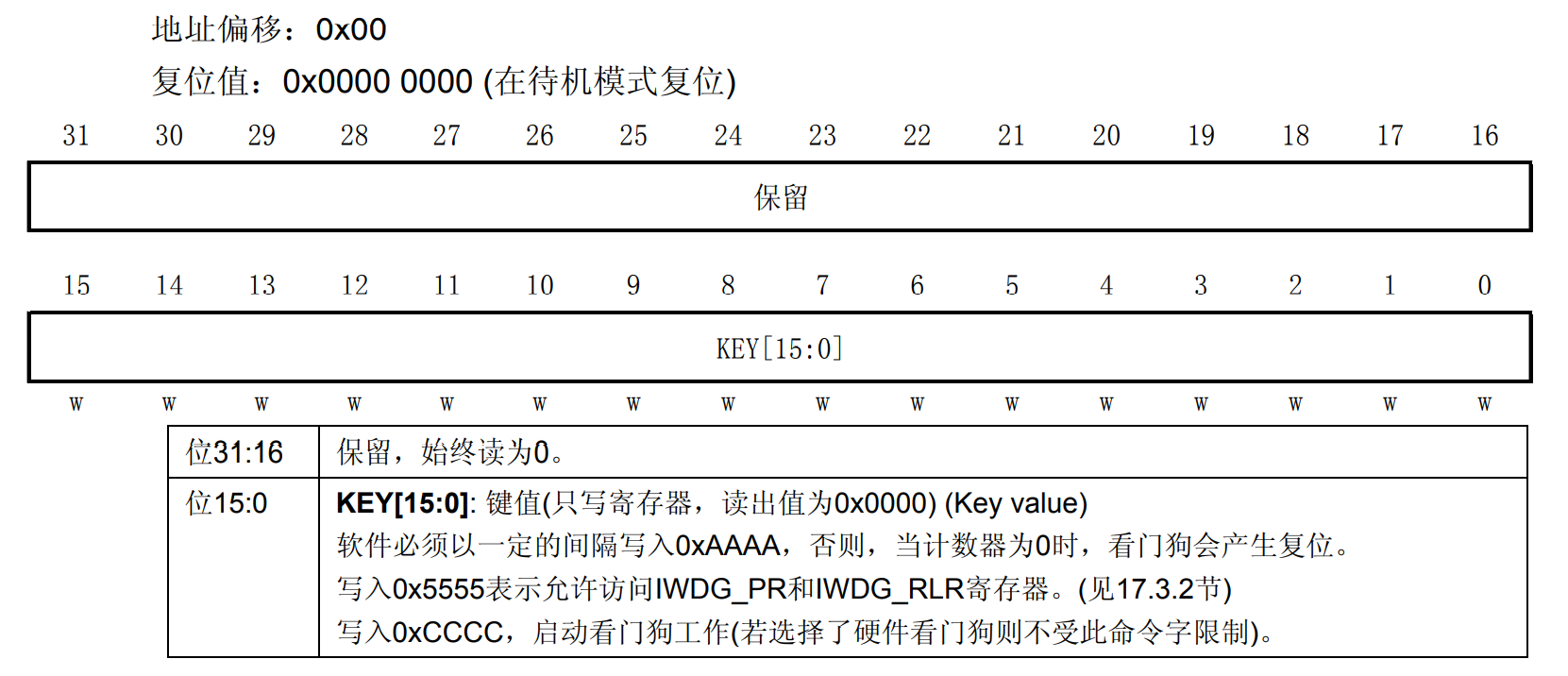
Key value register IWDG_KR can be said to be a control register of an independent watchdog. There are three main control modesKey value effect 0XAAAA Register iwdg_ Reload the value of RLR into the counter 0X5555 Allow access to IWDG_PR and IWDG_RLR register 0XCCCC Start the watchdog -
Prescaler register (IWDG_PR):
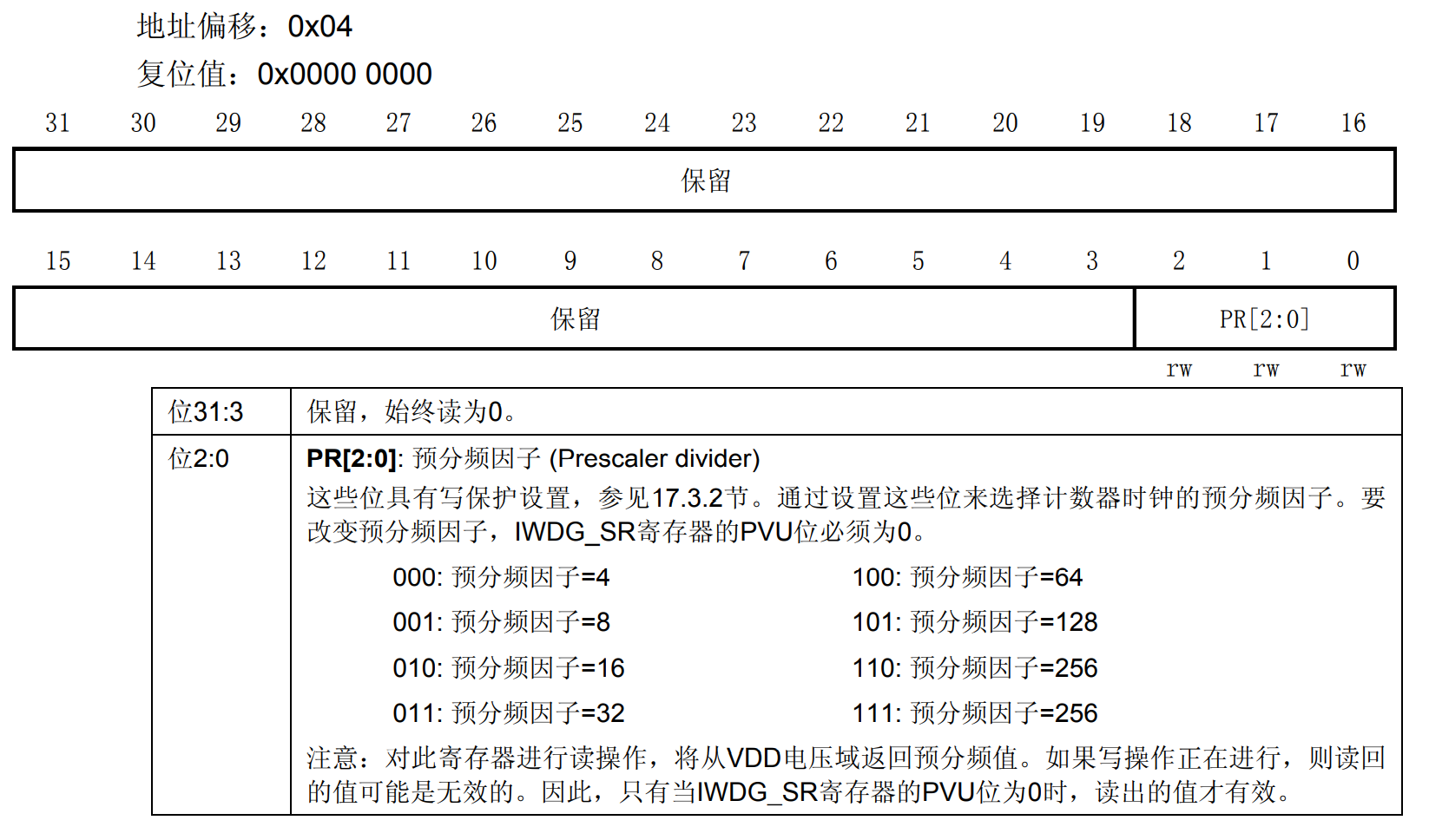
The clock of the down counter is obtained by the LSI through an 8-bit prescaler. We can operate the prescaler register IWDG_PR to set the frequency division factor, which can be: [4,8,16,32,64128256256], counter clock CK_CNT= 40/ 4*2^PRV, the clock counter will be reduced by one.
-
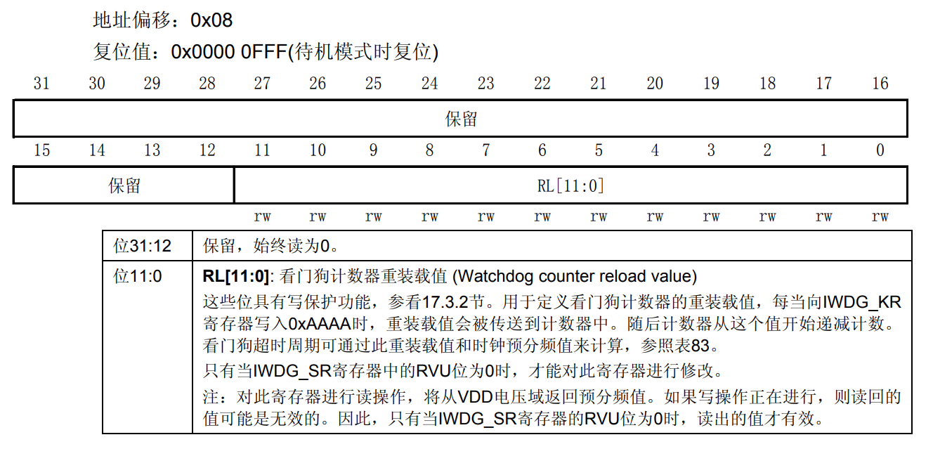
Reload register (IWDG_RLR):
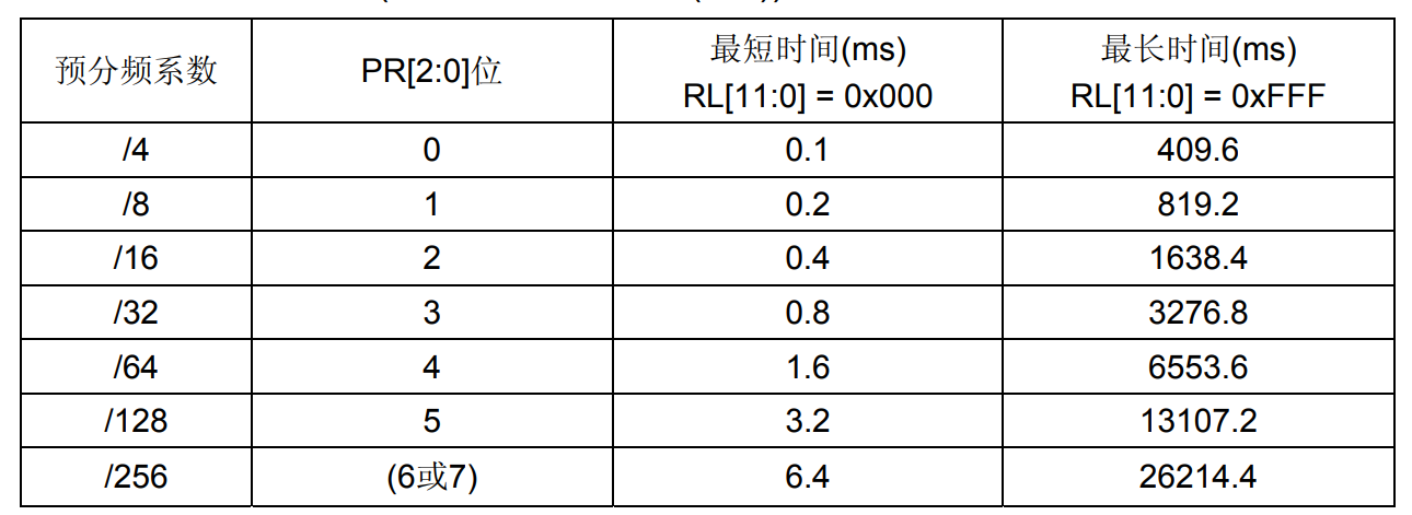
The reload register is a 12 bit register containing the value to be refreshed to the counter. The size of this value determines the overflow time of the independent watchdog. Timeout Tout = (4*2^prv) / 40 * rlv (s), prv is the value of prescaler register and rlv is the value of reload register.
-
Status register (IWDG_SR):
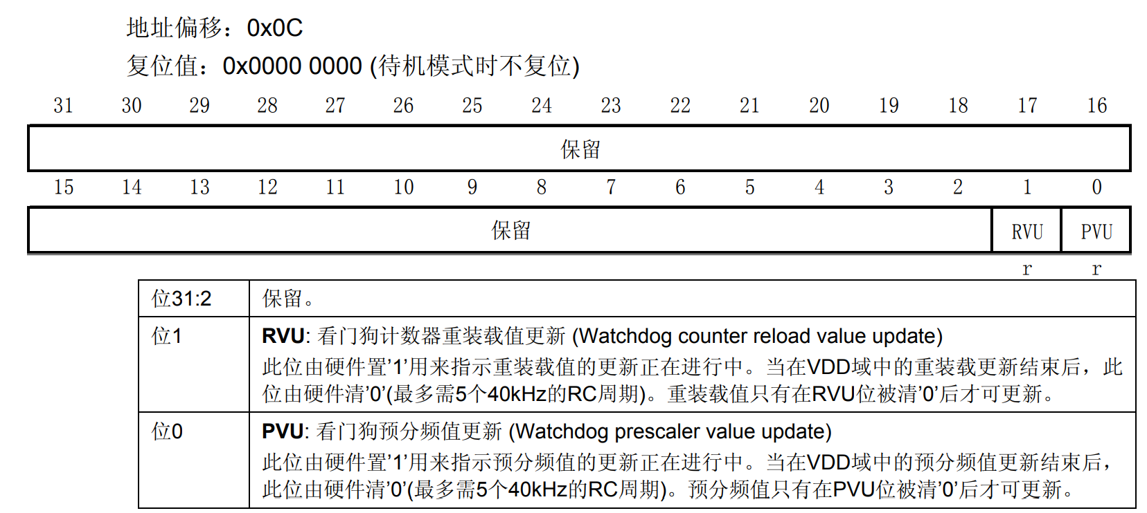
Note: if multiple reload values or prescaled values are used in the application, the preloaded value can be changed only after the RVU bit is cleared, and the prescaled value can be changed only after the PVU bit is cleared. However, after the pre frequency division and / or reassembly values are updated, the following code can continue to be executed without waiting for RVU or PVU reset. (that is, in the low-power mode, the write operation will still be completed.) -
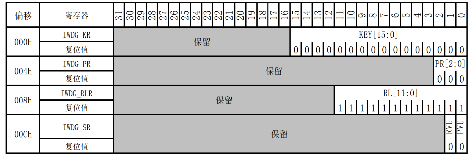
IWDG register image:
- Library function analysis
void IWDG_WriteAccessCmd(uint16_t IWDG_WriteAccess);//Cancel write protection: 0x5555 enable
void IWDG_SetPrescaler(uint8_t IWDG_Prescaler);//Set prescaler coefficient: write PR
void IWDG_SetReload(uint16_t Reload);//Set reload value: write RLR
void IWDG_ReloadCounter(void);//Feed dog: write 0xAAAA to KR
void IWDG_Enable(void);//Enable watchdog: write 0xCCCC to KR
FlagStatus IWDG_GetFlagStatus(uint16_t IWDG_FLAG);//Status: reload / prescaled update
- IWDG timeout test
Feed the dog by pressing the key. When the program is running normally, the led light is always on. When the program is not feeding the dog, the program flashes.
void IWDG_Init(u8 prer,u16 rlr)
{
    IWDG_WriteAccessCmd(IWDG_WriteAccess_Enable);  //Enable register IWDG_PR and iwdg_ Write operation of RLR
    IWDG_SetPrescaler(prer);  //Set IWDG prescaled value: set IWDG prescaled value to 64
    IWDG_SetReload(rlr);  //Set IWDG reload value
    IWDG_ReloadCounter();  //Reload the IWDG counter according to the value of the IWDG reload register
    IWDG_Enable();  //Enable IWDG
}

//Hey, independent watchdog
void IWDG_Feed(void)
{
 	IWDG_ReloadCounter();//reload
}
- main.c Documents
#include "stm32f10x.h"
#include "stm32f10x_exti.h"
#include "misc.h"
#include "stm32f10x_iwdg.h"

 /***************  Delay function*******************/
void Delay(__IO u32 nCount)
{
	for(; nCount != 0; nCount--);
}

 /***************  Configure the I/O port used by the LED*******************/
void LED_GPIO_Config(void)
{
	GPIO_InitTypeDef GPIO_InitStructure;

	RCC_APB2PeriphClockCmd( RCC_APB2Periph_GPIOB, ENABLE); // Enable PC port clock
	GPIO_InitStructure.GPIO_Pin = GPIO_Pin_12;	//Select the corresponding pin
	GPIO_InitStructure.GPIO_Mode = GPIO_Mode_Out_PP;
	GPIO_InitStructure.GPIO_Speed = GPIO_Speed_50MHz;
	GPIO_Init(GPIOB, &GPIO_InitStructure);  //Initialize PC port
	GPIO_SetBits(GPIOB, GPIO_Pin_12 );	 // Turn off the LED
}


//Gpioa_ Set 0 as drop-down input
void KEY_Init(void) //IO initialization
{
 	GPIO_InitTypeDef GPIO_InitStructure;

 	RCC_APB2PeriphClockCmd(RCC_APB2Periph_GPIOA,ENABLE);    //Enable PORTB,PORTE clock
	RCC_APB2PeriphClockCmd(RCC_APB2Periph_AFIO,ENABLE);	//Enable AFIO multiplexing function clock

	GPIO_InitStructure.GPIO_Pin  = GPIO_Pin_0;    // 0 pin
	GPIO_InitStructure.GPIO_Mode = GPIO_Mode_IPD;     // Set as drop-down input
 	GPIO_Init(GPIOA, &GPIO_InitStructure);    // Initialize GPIOA_0

}

void IWDG_Init(u8 prer,u16 rlr)
{
    IWDG_WriteAccessCmd(IWDG_WriteAccess_Enable);  //Enable register IWDG_PR and iwdg_ Write operation of RLR
    IWDG_SetPrescaler(prer);  //Set IWDG prescaled value: set IWDG prescaled value to 64
    IWDG_SetReload(rlr);  //Set IWDG reload value
    IWDG_ReloadCounter();  //Reload the IWDG counter according to the value of the IWDG reload register
    IWDG_Enable();  //Enable IWDG
}
//Hey, independent watchdog
void IWDG_Feed(void)
{
 	IWDG_ReloadCounter();//reload
}


int main(void)
{
	SystemInit();
	LED_GPIO_Config(); //LED port initialization
	KEY_Init();

	GPIO_SetBits(GPIOB, GPIO_Pin_12 );	 // Turn off the LED
	Delay(1000000);

	IWDG_Init(4,625);    //The number of and frequency division is 64, the overload value is 625, and the overflow time is 1s
	GPIO_ResetBits(GPIOB,GPIO_Pin_12);

	while (1)
	{
		if(GPIO_ReadInputDataBit(GPIOA,GPIO_Pin_0) == 1)
		{
			Delay(100);
			if(GPIO_ReadInputDataBit(GPIOA,GPIO_Pin_0) == 1)
			{
				IWDG_Feed();//If wk_ Press up to feed the dog
			}
		}
		Delay(10000);
	}

}
2, Window watchdog (WWDOG)
reference
Watchdog in STM32: https://blog.csdn.net/qq_36554582/article/details/82224648
Detailed usage of IWDG (independent watchdog) of STM32: https://blog.csdn.net/weibo1230123/article/details/80705866