1. Preface
A few months ago, the ChokCoco boss published an article:
CSS tricks | use drop shadow to achieve line light and shadow effect
In the article, a luminous heart-shaped line chasing each other is realized:

Now I'm just free to try WPF. In the implementation process, I use these knowledge and skills:
- Segoe Fluent Icon Font
- Create Path in Blend
- Calculate the long distance of Path
- Border animation for Path
- Design time data support for visual studio
- Custom Effect
This article will explain how to use these knowledge and skills to imitate his animation effects.
2. Icon font and Path
Although the ChokCoco boss has given a heart-shaped path, he can't expect what others give every time. For WPF developers, using icon fonts and Blend can easily create some simple paths.
First, find a heart-shaped Icon Font. On Windows 10/11, you can directly use Segoe MDL2 and Segoe Fluent fonts, which are built-in fonts of the system released with Windows 10/11. The following page lists the available Segoe Fluent fonts:
https://docs.microsoft.com/en-us/windows/apps/design/style/segoe-fluent-icons-font
Find the Unicode code point eb52 of HeartFill, then open Microsoft blend for visual studio 2019 (the updated version cuts off the functions used in this article), create a WPF application, and enter the following XAML in XAML:
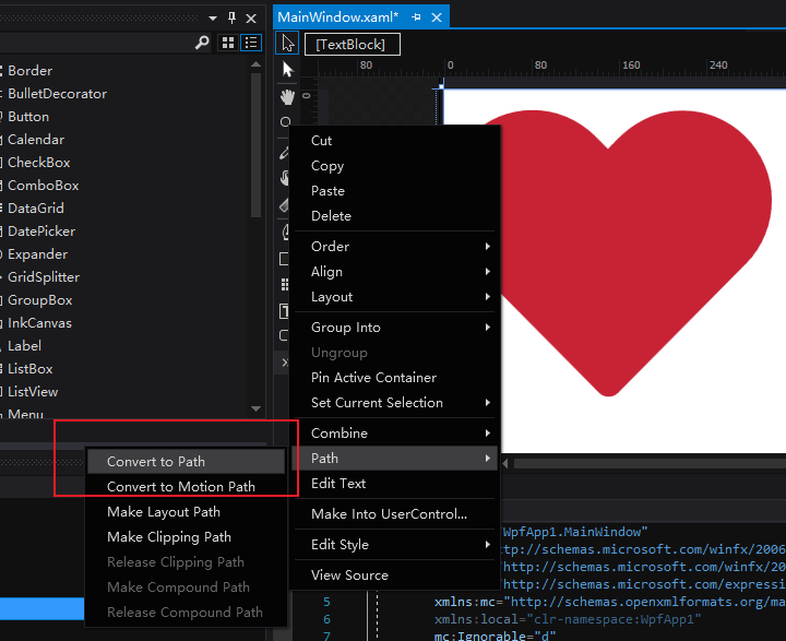
<TextBlock FontFamily="Segoe Fluent Icons" Text="" Foreground="#C72335" FontSize="300"/>
At this time, you should see a heart shape, which is the text Icon of HeartFill. Select it in the design view, right-click and select path - > Convert to path (in Chinese version, it should be converted to path):
In this way, TextBlock is converted to a Path of the same shape. Next, set Fill to empty, Stroke and StrokeThickness to Black and 10 respectively, and the shape of Path is as shown in the following figure. Select Pen tool in the left toolbar to adjust the shape of Path:
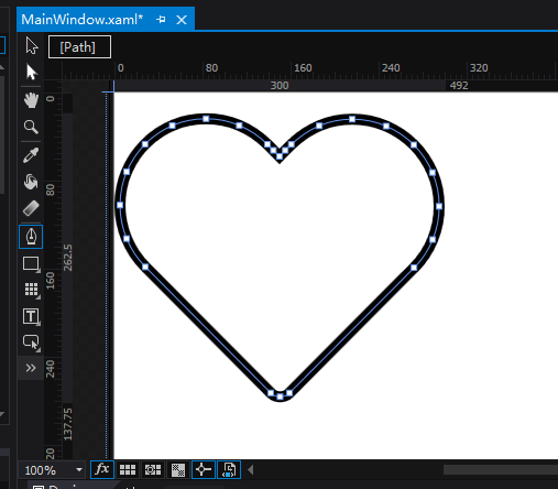
At this time, the corresponding XAML is as follows:
 <Path Margin="0,18.75,492,137.75"
       Data="M80.859375,18.75 C91.894524,18.75 102.31933,20.849609 112.13379,25.048828 C121.94823,29.248047 130.76172,35.205078 138.57422,42.919922 C140.52734,44.873062 142.40723,46.777359 144.21387,48.632813 C146.02051,50.488297 147.90039,52.392593 149.85352,54.345703 C151.70898,52.392593 153.54004,50.488297 155.34668,48.632813 C157.15332,46.777359 159.0332,44.92189 160.98633,43.066406 C168.89648,35.449219 177.66113,29.56543 187.28027,25.415039 C196.8994,21.264648 207.22655,19.189453 218.26172,19.189453 C229.58983,19.189453 240.23436,21.362305 250.19531,25.708008 C260.15625,30.053711 268.82324,35.961914 276.19629,43.432617 C283.56934,50.903336 289.37988,59.619156 293.62793,69.580078 C297.87598,79.541031 300,90.185562 300,101.51367 C300,112.25586 297.97363,122.68066 293.9209,132.78809 C289.86816,142.89551 284.0332,151.75781 276.41602,159.375 L159.375,277.58789 C156.93359,280.0293 153.95508,281.25 150.43945,281.25 C147.02148,281.25 144.0918,280.0293 141.65039,277.58789 L23.876953,158.64258 C16.259766,150.92773 10.375976,142.0166 6.2255859,131.90918 C2.0751953,121.80176 0,111.2793 0,100.3418 C0,89.111343 2.0996094,78.564468 6.2988281,68.701172 C10.498046,58.837906 16.235352,50.195328 23.510742,42.773438 C30.786131,35.351563 39.331055,29.492188 49.145508,25.195313 C58.959957,20.898438 69.53125,18.75 80.859375,18.75 z"
       RenderTransformOrigin="0.5,0.5"
       Stretch="Fill"
       Stroke="Black"
       StrokeThickness="10">
     <Path.RenderTransform>
         <TransformGroup>
             <ScaleTransform />
             <SkewTransform />
             <RotateTransform />
             <TranslateTransform />
         </TransformGroup>
     </Path.RenderTransform>
 </Path>
3. Calculate the long distance of Path
After getting the path, the next step is to calculate its length. This length does not need to be too precise. It can be used GetFlattenedPathGeometry Get the polygonal approximate Geometry of the PathGeometry object, and then calculate the length of each edge:
public double GetLength(Geometry geo)
{
    PathGeometry path = geo.GetFlattenedPathGeometry();
    double length = 0.0;
    foreach (PathFigure pf in path.Figures)
    {
        Point start = pf.StartPoint;
        foreach (PolyLineSegment seg in pf.Segments)
        {
            foreach (Point point in seg.Points)
            {
                length += (start - point).Length;
                start = point;
            }
        }
    }
    return length;
}
4. Border animation of path
The Path length calculated in the previous step is 898.
Then use StrokeDashArray and StrokeDashOffset to animate the border of Path. Because the StrokeThickness of Path is 10 pixels, all values must be divided by 10 when animating the border.
In the first step, set the StrokeDashArray to 29.9 59.9, which divides the border of Path into two parts. The first part is a solid line and the second part is blank.
In the second step, double animation is used to cycle the StrokeDashOffset from 0 to 89.8 to realize the continuous cycle of line animation.
The third step is to add the same Path and delay its animation by one second, so as to realize the chase animation of two heart-shaped lines.
<DoubleAnimation RepeatBehavior="Forever"
                 Storyboard.TargetName="P1"
                 Storyboard.TargetProperty="StrokeDashOffset"
                 To="89.8"
                 Duration="0:0:2" />

<DoubleAnimation RepeatBehavior="Forever" BeginTime="0:0:1"
                     Storyboard.TargetName="P2"
                     Storyboard.TargetProperty="StrokeDashOffset"
                     To="89.8"
                     Duration="0:0:2" />


<Path x:Name="P1" />
<Path x:Name="P2" d:StrokeDashOffset="45" />

For more information on border animation, you can refer to these two articles:
Practical Shape guide
Animate with Shape
5. Design time data of visual studio
Now we just need to let these two lights shine. But before that, we need to understand the concept of design time data in visual studio.
Design time data is the simulation data you set, which makes the control easier to visualize in XAML designer. d: Prefix is used to set the property value at design time. It only affects the design view and will not be compiled into the running application. For details, please refer to this document:
Using design time data with XAML designer in Visual Studio
This is a very practical trick. Because the above two paths overlap, it is difficult to distinguish them in the design view, so d:StrokeDashOffset="45" is used to stagger one of them. This paragraph only works in the design view and will not have other side effects.
6. Customize Effect
In WPF, DropShadowEffect is usually used for luminous effect. For example:
<Path x:Name="P1" >
    <Path.Effect>
        <DropShadowEffect BlurRadius="40" ShadowDepth="0"  Color="#f24983"/>
    </Path.Effect>
</Path>
<Path x:Name="P2" d:StrokeDashOffset="45" >
    <Path.Effect>
        <DropShadowEffect BlurRadius="40" ShadowDepth="0"  Color="#37c1ff"/>
    </Path.Effect>
</Path>

But the color is too light, too light. To solve this problem, one way is to overlay multiple paths so that their drop shadows will also be superimposed to achieve a very bright lighting effect. However, it is necessary to animate multiple paths superimposed here. I'm afraid the performance will be very problematic.
Another way is to customize an Effect. Its code only needs the following lines:
float Amount : register(C0);

float4 main(float2 uv : TEXCOORD) : COLOR
{
    float4 srcColor = tex2D(input, uv);
    srcColor.rgb *= Amount;
    srcColor.a  *= Amount;
    return srcColor;
}
This is just a very simple Effect, which is to multiply the color and transparency of all pixels by a specified value. I don't know the name of this Effect, but because it finally realizes the luminous Effect, it is named GlowEffect. Use the GlowEffect with the BlurEffect to brighten the dim color above:
<Grid>
    <Grid.Effect>
        <effects:GlowEffect Amount="5" />
    </Grid.Effect>
    <Grid>
        <Grid.Effect>
            <BlurEffect Radius="70" RenderingBias="Quality" />
        </Grid.Effect>
        <Path x:Name="P1b" Stroke="#f24983" />
        <Path x:Name="P2b"
              d:StrokeDashOffset="45"
              Stroke="#37c1ff" />
    </Grid>
</Grid>
<Grid>
    <Path x:Name="P1" />
    <Path x:Name="P2" d:StrokeDashOffset="45" />
</Grid>

For more information about customizing Effect, please refer to this article by Walter LV:
Getting started with WPF pixel shader: write HLSL pixel shader code using Shazzam Shader Editor
7. Results
The final results are as follows: