Programming environment: Ubuntu Kylin 16.04
Code warehouse: https://gitee.com/AprilSloan/linux0.11-project
linux0.11 source code download (it cannot be compiled directly and needs to be modified)
1. Add kernel
After entering the kernel, it does not immediately enter the main function. In the previous chapter, gdt is only set temporarily. In addition, idt and other initialization operations should be set. These contents should also be written in assembly. Here, the assembly in at & T format is adopted.
The following is head The content of S is still an endless loop for simplicity.
.globl startup_32
startup_32:
    jmp startup_32
The first line is to enable external files to use startup_32. The kernel not only needs to compile, but also needs links. Here we need to write a link control script named kernel lds.
OUTPUT_FORMAT("elf32-i386", "elf32-i386", "elf32-i386")
OUTPUT_ARCH(i386)
ENTRY(startup_32)
SECTIONS
{
	.text :
	{
		_text = .;
		*(.text)
		_etext = .;
	}
	. = ALIGN(8);
	.data :
	{
		_data = .;
		*(.data)
		_edata = .;
	}
	.bss :
	{
		_bss = .;
		*(.bss)
		_ebss = .;
	}
	_end = .;
}
It is defined here that the output format and architecture are 386, and the function entry is specified as startup_32. Merge the text segment, data segment and bss segment of each file_ End is the end address of the kernel, which will be used later.
At the same time, you need to add head. In Makefile Compilation Rules for S.
LD	=ld
LDFLAGS	=-m elf_i386

default: all

all: Image

Image: mkimg boot/bootsect.bin boot/setup.bin system
	objcopy -O binary -R .note -R .comment system kernel
	dd if=boot/bootsect.bin of=kernel.img bs=512 count=1 conv=notrunc
	dd if=boot/setup.bin of=kernel.img bs=512 count=4 seek=1 conv=notrunc
	dd if=kernel of=kernel.img bs=512 count=1 seek=5 conv=notrunc
	rm kernel -f
	bochs -qf bochsrc

boot/head.o: boot/head.s
	gcc -m32 -traditional -c boot/head.s -o boot/head.o

system:	boot/head.o
	$(LD) $(LDFLAGS) boot/head.o -o system -T kernel.lds
	nm system | grep -v '\(compiled\)\|\(\.o$$\)\|\( [aU] \)\|\(\.\.ng$$\)\|\(LASH[RL]DI\)'| sort > System.map

boot/bootsect.bin: boot/bootsect.s
	nasm boot/bootsect.s -o boot/bootsect.bin

boot/setup.bin: boot/setup.s
	nasm boot/setup.s -o boot/setup.bin

mkimg:
	./mkimg.sh

clean:
	rm -rf boot/*.bin boot/*.o System.map system kernel.img
Here, gcc is used to compile head s. After that, a file named system is generated through the link script, which also generates system Map, which records the addresses of all functions and global variables in the kernel, which is very useful in debugging. Remove the annotation information in the system, generate the kernel, and successively set bootect bin,setup.bin and kernel are written to the floppy disk. For convenience, it is assumed that the kernel only occupies one sector, which will be improved in the following sections.
head.s is not finished yet. After all, bootect S does not put head S is loaded into memory. Let's add this part.
SETUPLEN    equ 4
BOOTSEG     equ 0x07c0
INITSEG     equ 0x9000
SETUPSEG    equ 0x9020
SYSSEG      equ 0x1000

start:
    mov ax, BOOTSEG
    mov ds, ax
    mov ax, INITSEG
    mov es, ax
    mov cx, 256
    sub si, si
    sub di, di
    rep
    movsw           ; take bootsect.s From 0 x7c00 Move to 0 x90000
    jmp INITSEG:go
go: mov ax, cs
    mov ds, ax
    mov es, ax
    mov ss, ax
    mov sp, 0xff00

load_setup:
    mov dx, 0x00
    mov cx, 0x02
    mov bx, 0x0200
    mov ax, 0x0200 + SETUPLEN
    int 0x13        ; load setup.s To 0 x90200
    jnc ok_load_setup
    mov dx, 0x00
    mov ax, 0x00
    int 0x13
    jmp load_setup  ; If loading fails, reset the floppy disk and reload it

ok_load_setup:
    mov ah, 0x03
    xor bh, bh
    int 0x10        ; Get cursor position

    mov cx, 24
    mov bx, 0x0007
    mov bp, msg
    mov ax, 0x1301
    int 0x10        ; Print string

load_system:
    mov ax, SYSSEG
    mov es, ax
    mov dx, 0x00
    mov cx, 0x06
    mov bx, 0x00
    mov ax, 0x0201
    int 0x13        ; load head.s To 0 x10000
    jnc ok_load_system
    mov dx, 0x00
    mov ax, 0x00
    int 0x13
    jmp load_system ; If loading fails, reset the floppy disk and reload it

ok_load_system:
    jmp SETUPSEG:0  ; Jump to setup.s Content of

msg:
    db 13, 10
    db "Loading system ..."
    db 13, 10, 13, 10

    times 0x1fe - ($ - $$) db 0 ; Fill in 0 until 0 x1fe
    dw 0xaa55       ; Boot disk ID
This modification adds load_ The code of system is the same as that of load_setup is similar.
Is this ready for debugging? No, no, No. when setting gdt in the previous chapter, the starting address of the code segment is set to 0, and now the kernel address is 0x10000. We also need to move the kernel from 0x10000 to 0. This part of the function is in setup Completed in S.
INITSEG     equ 0x9000
SYSSEG      equ 0x1000
SETUPSEG    equ 0x9020

start:
    cli     	; The interrupt mechanism in the protection mode has not been established, and the interrupt shall be prohibited
    mov ax, 0x00
    cld
do_move:
    mov es, ax
    mov ax, SYSSEG
    mov ds, ax
    sub di, di
    sub si, si
    mov cx, 256
    rep
    movsw       ; Change a sector from 0 x10000 Move to 0 x00

end_move:
    mov ax, SETUPSEG
    mov ds, ax
    lgdt    [gdt_48]    ; load gdtr

    mov al, 2
    out 0x92, al        ; open A20

    mov ax, 0x0001
    lmsw    ax          ; set up CR0 of PE position
    jmp 8:0

gdt:
    dw  0, 0, 0, 0
    dw  0x07ff, 0x0000, 0x9a00, 0x00c0
    dw  0x07ff, 0x0000, 0x9200, 0x00c0

gdt_48:
    dw  0x800
    dw  512 + gdt, 0x9  ; 0x90200+gdt
Mobile kernel code and bootect S moves similar to its own code. In addition, change the dead loop to jump to the kernel. Here we need to focus on the meaning of jmp 8:0. jmp 8:0 is the same as the previous bootect The meaning of jmp SETUPSEG:0 in S is different. Note that we have turned on the protection mode. 8 here represents the segment selector. Please see the figure below.

TI=0 means in GDT (Global Descriptor Table), 1 means in LDT (local descriptor table), RPL means priority, and 0 is the highest. Therefore, 8 represents the segment descriptor with index 1 (the segment descriptor with index 0 is empty). The priority of this segment descriptor is 0, which is in GDT. This segment descriptor is setup S code snippet set on line 32.
OK, you can start debugging now. You can run step by step and see the running process. You can also jump to here directly at the interrupt point at address 0 like me.
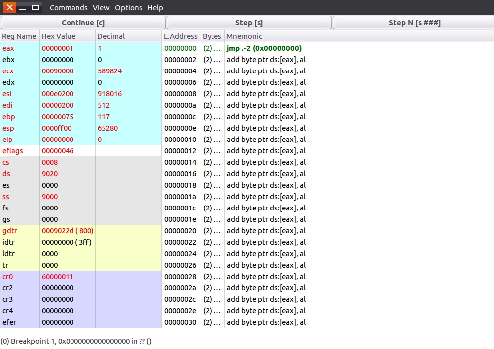
You can see the head S, running successfully!
The next section will further improve the loading and moving of the kernel. After all, the code of the kernel can't be loaded in one sector.
2. Improve kernel loading and moving
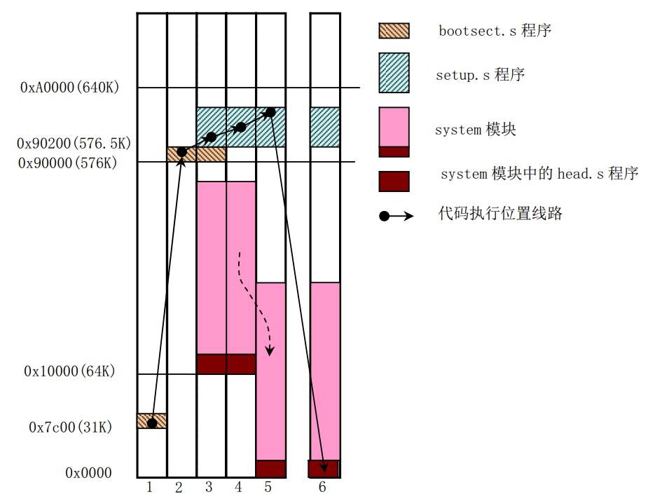
As can be seen from the above figure, bootect S load the kernel to the address starting from 0x10000, setup S moves the kernel to the address from 0. Linus believes that for Linux 0.0 In version 11, the kernel has a maximum of 192KB (0x30000384 sectors), so only these sectors are loaded into memory in the program.
Set bootect S after modification:
SYSSIZE     equ 0x3000
SETUPLEN    equ 4
BOOTSEG     equ 0x07c0
INITSEG     equ 0x9000
SETUPSEG    equ 0x9020
SYSSEG      equ 0x1000
ENDSEG      equ SYSSEG + SYSSIZE

start:
    mov ax, BOOTSEG
    mov ds, ax
    mov ax, INITSEG
    mov es, ax
    mov cx, 256
    sub si, si
    sub di, di
    rep
    movsw           ; take bootsect.s From 0 x7c00 Move to 0 x90000
    jmp INITSEG:go
go: mov ax, cs
    mov ds, ax
    mov es, ax
    mov ss, ax
    mov sp, 0xff00

load_setup:
    mov dx, 0x00
    mov cx, 0x02
    mov bx, 0x0200
    mov ax, 0x0200 + SETUPLEN
    int 0x13        ; load setup.s To 0 x90200
    jnc ok_load_setup
    mov dx, 0x00
    mov ax, 0x00
    int 0x13
    jmp load_setup  ; If loading fails, reset the floppy disk and reload it

ok_load_setup:
    mov dl, 0x00
    mov ax, 0x0800
    int 0x13        ; Gets the number of sectors per track
    mov ch, 0x00
    mov [sectors], cx
    mov ax, INITSEG
    mov es, ax

    mov ah, 0x03
    xor bh, bh
    int 0x10        ; Get cursor position

    mov cx, 24
    mov bx, 0x0007
    mov bp, msg
    mov ax, 0x1301
    int 0x10        ; Print string

    mov ax, SYSSEG
    mov es, ax
    call    read_it
    call    kill_motor

    jmp SETUPSEG:0  ; Jump to setup.s Content of

read_it:
    mov ax, es
    test    ax, 0x0fff
die:jne     die
    xor bx, bx
rp_read:
    mov ax, es
    cmp ax, ENDSEG
    jb  ok1_read
    ret
ok1_read:
    mov ax, [sectors]
    sub ax, [sread]
    mov cx, ax
    shl cx, 9
    add cx, bx
    jnc ok2_read
    je  ok2_read
    xor ax, ax
    sub ax, bx
    shr ax, 9
ok2_read:
    call    read_track
    mov cx, ax
    add ax, [sread]
    cmp ax, [sectors]
    jne ok3_read
    mov ax, 1
    sub ax, [head]
    jne ok4_read
    push ax
    mov ax, [track]
    inc ax
    mov [track], ax
    pop ax
ok4_read:
    mov [head], ax
    xor ax, ax
ok3_read:
    mov [sread], ax
    shl cx, 9
    add bx, cx
    jnc rp_read
    mov ax, es
    add ax, 0x1000
    mov es, ax
    xor bx, bx
    jmp rp_read

read_track:
    push    ax
    push    bx
    push    cx
    push    dx
    mov dx, [track]
    mov cx, [sread]
    inc cx
    mov ch, dl
    mov dx, [head]
    mov dh, dl
    mov dl, 0x00
    and dx, 0x0100
    mov ah, 2
    int 0x13
    jc  bad_rt
    pop dx
    pop cx
    pop bx
    pop ax
    ret
bad_rt:
    mov ax, 0
    mov dx, 0x00
    int 0x13
    pop dx
    pop cx
    pop bx
    pop ax
    jmp read_track

kill_motor:
    push    dx
    mov dx, 0x3f2
    mov al, 0
    out dx, al
    pop dx
    ret

sread:
    dw  1 + SETUPLEN
head:
    dw  0
track:
    dw  0
sectors:
    dw  0

msg:
    db 13, 10
    db "Loading system ..."
    db 13, 10, 13, 10

    times 0x1fe - ($ - $$) db 0 ; Fill in 0 until 0 x1fe
    dw 0xaa55       ; Boot disk ID
Lines 39-43 are to obtain the number of sectors per track and save them.
The most difficult thing to understand in this code is read_it to kill_ The code used to read sectors between motors. I write this code in the form of C language pseudo code to help you understand.
#define SYSSIZE 0x3000
#define SETUPLEN 4
#define SYSSEG 0x1000
#define ENDSEG SYSSEG + SYSSIZE	// 0x4000

short ax = SYSSEG, bx, cx, dx, es = SYSSEG;
short sread = 1 + SETUPLEN, head = 0, track = 0, sectors = 18;

void read_it(void) {
	if (ax & 0xfff)
		while (1);			// die
	bx = 0;
	while (1) {				// rp_read
		ax = es;
		if (ax >= ENDSEG)
			return;
		ax = sectors;		// ok1_read
		ax -= sread;		// The number of sectors to be read under the current track and head
		cx = ax;
		cx *= 512;			// Number of bytes to read
		cx += bx;			// Total bytes read after reading
		if (cx overflow && cx != 0) {
			ax = 0x10000 - bx;
			ax /= 512;
		}
		read_track();		// ok2_read
		cx = ax;
		ax += sread;		// The number of sectors read under the current track and head
		if (ax = sectors) {	// If all sectors of the current track and head are read
			if (head == 1) {
				track++;	// Change track
			}
			head = !head;	// ok4_read 	 Change head
			ax = 0;
		}
		sread = ax;			// ok3_read
		cx *= 512;
		bx += cx;			// Update data storage address
		if (bx No overflow)
			continue;
		es += 0x1000;
		bx = 0;				// After reading 64KB data, update the data storage address
	}
}

void read_track(void) {
	while (1) {				// read_track
    	push ax,bx,cx,dx
		cx = track;
		cx <<= 8;
		cx += sread + 1;
		dx = head;
		dx <<= 8;
		dx &= 0x0100;
		ax &= 0x00ff;
		ax |= 0x0200;
		int 0x13;
        if (Read successful) {
            pop ax,bx,cx,dx
            return;
        }
		else {				// bad_rt
			ax = 0;
			dx = 0;
			int 0x13;
            pop ax,bx,cx,dx
		}
	}
}
Combined with c language pseudo code and assembly code, I believe it is easier for you to understand. The operation of reading sectors here is somewhat complicated. Since I already know the number of sectors to be read and the address to be stored, can I read them all at one time? The answer is No. Let's review the BIOS interrupt knowledge of reading sectors again.
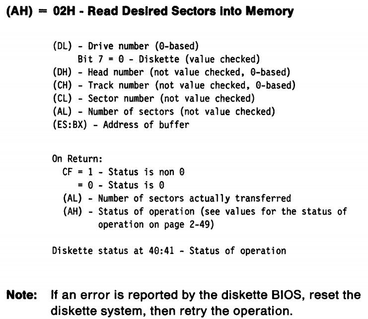
Each time we read sectors, we need to specify tracks and heads, and each track of the floppy disk we created has 18 sectors, so we can read up to 18 sectors at a time. Moreover, we should also pay attention to the sector number. The sector number is composed of track, head and sector. The sector number starts from 1, and the kernel is stored in sectors 6 to 389.
- Sector 1 = > track = 0, head = 0, sector = 1
- Sector 2 = > track = 0, head = 0, sector = 2
- ...
- Sector 19 = > track = 0, head = 1, sector = 1
- ...
- Sector 37 = > track = 1, head = 0, sector = 1
So every time you call read_ The values of head and track should be updated after track. In addition, the number of sectors read is not necessarily 18. For example, only sectors 6-18 are read for the first time.
kill_ There is no need to explain the code after motor. We have read all the data of the floppy disk. At this time, the floppy disk is useless. Turn off its motor.
Next, you need to modify setup Content of S.
INITSEG     equ 0x9000
SYSSEG      equ 0x1000
SETUPSEG    equ 0x9020

start:
	cli         		; The interrupt mechanism in the protection mode has not been established, and the interrupt shall be prohibited
    mov ax, 0x00
    cld
do_move:                ; Remove kernel from 0 x10000 Move to 0 x00
    mov es, ax
    add ax, 0x1000
    cmp ax, 0x9000
    jz  end_move
    mov ds, ax
    sub di, di
    sub si, si
    mov cx, 0x8000
    rep
    movsw               ; 64 per move KB content
    jmp do_move

end_move:
    mov ax, SETUPSEG
    mov ds, ax
    lgdt    [gdt_48]    ; load gdtr

    mov al, 2
    out 0x92, al        ; open A20

    mov ax, 0x0001
    lmsw    ax          ; set up CR0 of PE position
    jmp 8:0

gdt:
    dw  0, 0, 0, 0
    dw  0x07ff, 0x0000, 0x9a00, 0x00c0
    dw  0x07ff, 0x0000, 0x9200, 0x00c0

gdt_48:
    dw  0x800
    dw  512 + gdt, 0x9  ; 0x90200+gdt
Compared with the previous section, there are few changes, only do is modified_ Content under move. Now, the program will move 0x10000-0x90000 data to 0-0x80000 address, and move 64KB data each time.
This section is head S will not be changed. After all, changing some contents will not produce flowers. Add something in the next section.
Finally, make a small modification to Makefile.
Image: mkimg boot/bootsect.bin boot/setup.bin system
	objcopy -O binary -R .note -R .comment system kernel
	dd if=boot/bootsect.bin of=kernel.img bs=512 count=1 conv=notrunc
	dd if=boot/setup.bin of=kernel.img bs=512 count=4 seek=1 conv=notrunc
	dd if=kernel of=kernel.img bs=512 count=384 seek=5 conv=notrunc
	rm kernel -f
	bochs -qf bochsrc
Only the content of line 5 is modified, and the amount of data written to the kernel is changed. Otherwise, even if bootect. Is modified s. There is only one sector of data loaded into memory.
Run it to see if there are any errors. (if you jump directly to address 0, you need to wait for a period of time, because the floppy disk is slow to load sectors)
Anyway, it must be right, otherwise I wouldn't write it. This is for the sake of water space.
3. Start writing the kernel
After entering the kernel, you need to do a lot of initialization operations. Now, you need to reload gdt and set idt, so you need to reset head S make the following changes:
.text
.globl idt, gdt
.globl startup_32
startup_32:
    movl    $0x10, %eax
    mov %ax, %ds
    mov %ax, %es
    mov %ax, %fs
    mov %ax, %gs
    lss stack_start, %esp
    call setup_idt
    call setup_gdt
    movl    $0x10, %eax
    mov %ax, %ds
    mov %ax, %es
    mov %ax, %fs
    mov %ax, %gs
    lss stack_start, %esp
    jmp .

setup_idt:
    lidt    idt_descr
    ret

setup_gdt:
    lgdt    gdt_descr
    ret

.align  4
.word   0
idt_descr:
	.word   256 * 8 - 1
	.long   idt

.align  4
.word   0
gdt_descr:
	.word   256 * 8 - 1
	.long   gdt

.align  8
idt:.fill   256, 8, 0

gdt:.quad   0x0000000000000000
	.quad   0x00c09a0000000fff
	.quad   0x00c0920000000fff
	.quad   0x0000000000000000
	.fill   252, 8, 0
When entering the protection mode, first set the segment register, and set the stack segment register and stack pointer register, so that the stack pointer register points to the end of the user stack array. Where stack_start is defined in main C.
Next, set idt and gdt. idt is the interrupt descriptor table, which is used to specify the address of exception or interrupt service function. gdt has been mentioned before and will not be repeated. Both functions are simple. Both idt and gdt have 256 table entries. Now only the contents of idt are set to 0, while the contents of gdt are the same as setup The settings in s are similar, except that the segment limit is changed.
After setting idt and gdt, you need to reset each segment register and stack related register, and finally enter the dead loop (I can't find other end methods).
A new file has been added in this section: main c. I will save the data of the user stack in this file. In the following chapters, I will write the main function in this file.
#define PAGE_SIZE   4096

long user_stack[PAGE_SIZE >> 2];

struct {
	long *a;
	short b;
} stack_start = {&user_stack[PAGE_SIZE >> 2], 0x10};
Here, a page size of 4096 bytes and a user stack size of 4096 bytes are defined.
Because a new file is added, you need to change the Makefile and add main C, and put main O used in the Compilation Rules of other files. Of course, don't forget to add it under clean.
AS	=as --32
LD	=ld
LDFLAGS	=-m elf_i386
CC	=gcc -march=i386
CFLAGS	=-Wall -O2 -m32 -fomit-frame-pointer -fno-stack-protector

default: all

all: Image

Image: mkimg boot/bootsect.bin boot/setup.bin system
	objcopy -O binary -R .note -R .comment system kernel
	dd if=boot/bootsect.bin of=kernel.img bs=512 count=1 conv=notrunc
	dd if=boot/setup.bin of=kernel.img bs=512 count=4 seek=1 conv=notrunc
	dd if=kernel of=kernel.img bs=512 count=384 seek=5 conv=notrunc
	rm kernel -f
	bochs -qf bochsrc

boot/head.o: boot/head.s
	gcc -m32 -traditional -c boot/head.s -o boot/head.o

system:	boot/head.o init/main.o
	$(LD) $(LDFLAGS) boot/head.o init/main.o \
	-o system -T kernel.lds
	nm system | grep -v '\(compiled\)\|\(\.o$$\)\|\( [aU] \)\|\(\.\.ng$$\)\|\(LASH[RL]DI\)'| sort > System.map

boot/bootsect.bin: boot/bootsect.s
	nasm boot/bootsect.s -o boot/bootsect.bin

boot/setup.bin: boot/setup.s
	nasm boot/setup.s -o boot/setup.bin

mkimg:
	./mkimg.sh

clean:
	rm -rf boot/*.bin boot/*.o init/*.o System.map system kernel.img

init/main.o: init/main.c
	$(CC) $(CFLAGS) -nostdinc -Iinclude -c -o $*.o $<
Run it.
Finally, it runs to the dead cycle, indicating that there is no problem. You can see whether the values of esp, ss, gdtr, idtr and other registers are consistent with the expectation. This section contains less content and is not difficult to understand. Let's hurry to the next section.
4. Set page table
This section sets the page directory and page table. Assign 0x0-0x1000 to page directory, 0x1000-0x2000 to page table 0, 0x2000-0x3000 to page table 1, 0x3000-0x4000 to page table 2, and 0x4000-0x5000 to page table 3. All page tables should be recorded in the page directory. Pages should be recorded in the page table. A page directory item records the address of a page table, accounting for 4 bytes. A page table item records the address of a page, accounting for 4 bytes. The page size is 4KB, so each page table can record the use of 4MB memory and each page directory can record the use of 4GB memory. Here, we only use four page tables and only address 16MB of memory.
You may ask, isn't there a code for the 0x0 address? How can I give the page directory? It is true that this address has code, but when the code is executed, it can be overwritten, which is equivalent to removing the grind and killing the donkey.
Modified head S is as follows:
.text
.globl idt, gdt, pg_dir, tmp_floppy_area
pg_dir:
.globl startup_32
startup_32:
    movl    $0x10, %eax
    mov %ax, %ds
    mov %ax, %es
    mov %ax, %fs
    mov %ax, %gs
    lss stack_start, %esp
    call setup_idt
    call setup_gdt
    movl    $0x10, %eax
    mov %ax, %ds
    mov %ax, %es
    mov %ax, %fs
    mov %ax, %gs
    lss stack_start, %esp
    xorl    %eax, %eax
1:  incl    %eax        # Check whether A20 is turned on
    movl    %eax, 0x0
    cmpl    %eax, 0x100000
    je 1b

    jmp after_page_tables

setup_idt:
    lidt    idt_descr
    ret

setup_gdt:
    lgdt    gdt_descr
    ret

.org    0x1000
pg0:

.org    0x2000
pg1:

.org    0x3000
pg2:

.org    0x4000
pg3:

.org    0x5000

tmp_floppy_area:
    .fill   1024, 1, 0

after_page_tables:
    pushl   $0
    pushl   $0
    pushl   $0
    pushl   $L6     # Set the return address of the main function
    pushl   $main   # Setup_ The return address of paging is the main function
    jmp setup_paging
L6: jmp L6

.align  4
setup_paging:
    movl    1024 * 5, %ecx
    xorl    %eax, %eax
    xorl    %edi, %edi
    cld
    rep
    stosl
    movl    $pg0 + 7, pg_dir
    movl    $pg1 + 7, pg_dir + 4
    movl    $pg2 + 7, pg_dir + 8
    movl    $pg3 + 7, pg_dir + 12   # Set page table information in page directory
    movl    $pg0, %edi
    movl    $0x0007, %eax
1:  stosl
    addl    $0x1000, %eax
    cmpl    $0x1000007, %eax
    jne 1b                  # Set page information
    xorl    %eax, %eax
    movl    %eax, %cr3
    movl    %cr0, %eax
    orl $0x80000000, %eax
    movl    %eax, %cr0      # Set the PG bit of CR0 to enable paging
    ret

.align  4
.word   0
idt_descr:
	.word   256 * 8 - 1
	.long   idt

.align  4
.word   0
gdt_descr:
	.word   256 * 8 - 1
	.long   gdt

.align  8
idt:.fill   256, 8, 0

gdt:.quad   0x0000000000000000
	.quad   0x00c09a0000000fff
	.quad   0x00c0920000000fff
	.quad   0x0000000000000000
	.fill   252, 8, 0
First in the head A PG is set at the beginning of S_ Dir tag, which is used to indicate the address of the page directory. Then set the segment register, stack, idt and gdt, and then check whether A20 is turned on. If A20 is not turned on, the content of 0 address will be the same as that of 0x100000(1MB). Here, please note that at & T assembly memory addressing uses numbers directly, such as 0x100000, while Intel assembly memory addressing uses numbers enclosed in square brackets, such as [0x100000]. je 1b in line 24 means that if ZF=1, it will jump to the previous label with the name of 1, that is, the label of 1 in line 21.
Lines 36-46 set the addresses of the four page tables org 0x1000 means that the program or data after this statement takes 0x1000 as the starting address, so the address of pg0 label is 0x1000. Similarly, the address of pg1 label is 0x2000, the address of pg2 label is 0x3000, and the address of pg3 label is 0x4000.
tmp_floppy_area defines a memory block for floppy disk driver, which is used when DMA cannot access the buffer block.
after_ page_ The first three lines of tables set the parameters of the main function, pushl $L6 sets the return address of the main function (L6 is an endless loop), and pushl $main pushes the address of the main function into the stack. This paragraph should be consistent with setup_ The ret instruction of paging is understood together. The function of ret is to take out the value at the top of the stack and put it into eip for setup_ There is no stack in and stack out operation in paging, so when ret is executed, the address of the main function will be put into the eip. At this time, the program continues to execute from the main function. Very clever operation.
cld rep stosl these three instructions mean: load the data of eax into the address pointed to by es:edi, increase edi and decrease ecx until ecx is 0. Therefore, the purpose of lines 64-69 is to fill the contents of 0x0-0x5000 with 0, that is, to clear the page directory and page table.
Lines 70-73 set the page table information in the page directory. The structure of page directory entries is as follows:
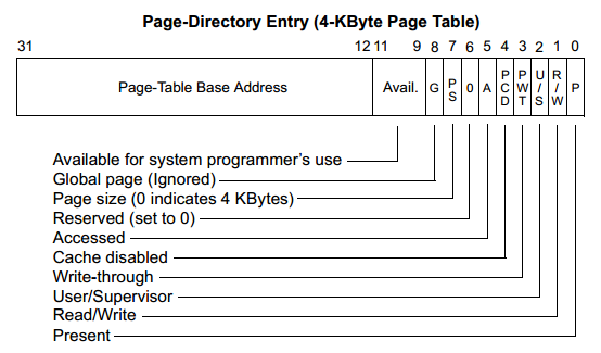
| field | significance |
|---|---|
| P | There are bits. A value of 1 indicates that the page table or page is in memory. Otherwise, it means it is not in memory |
| R/W | Read write flag. A value of 1 indicates that the page can be read and written, and a value of 0 indicates that it is read-only. When the processor is running at level 1 and 2, the privilege does not work. |
| U/S | User / super user flag. When it is 1, program access of all privilege levels is allowed; When it is 0, only programs with privilege levels of 0, 1 and 2 are allowed to access. |
| PWT | Write through flag bit of Page level. When it is 1, use the write through Cache type; The Cache type of write back is used when it is 0. When CR0 When CD = 1 (Cache is disabled), this flag is ignored. |
| PCD | Page level Cache Disable flag bit. When it is 1, the physical page cannot be cached; Allow Cache when is 0. When CR0 When CD = 1 (Cache is disabled), this flag is ignored. |
| A | Access bit. This bit is set by the processor firmware to indicate whether the page pointed to by this table item has been accessed (read or write). Once set, the processor never knows this flag bit. This bit can be used by the operating system to monitor the frequency of page usage. |
| PS | Page Size bit. When it is 0, the size of the page is 4KB; When it is 1, the Page Size is 4MB (normal 32-bit address addressing) or 2MB (if extended physical address addressing is enabled) |
| G | Global bit. If the page is global, it will remain in the cache. |
| Avail. | The processor can be ignored and the software can be used. |
| Page-Table Base Address | Page table base address |
We use movl $pg0 + 7, pg_dir as an example. The address of pg0 is 0x1000. This statement sets the first page directory table entry to 0x1007. At this time, the base address of page table 0 is 1 (4KB aligned), and the page size is 4KB. It can be accessed by programs at all privilege levels, readable and writable, and has been stored in memory. We can understand page table 1, page table 2 and page table 3 in the same way.
Lines 74-79 are used to set page table entries. The structure of page table items is shown in the following figure:
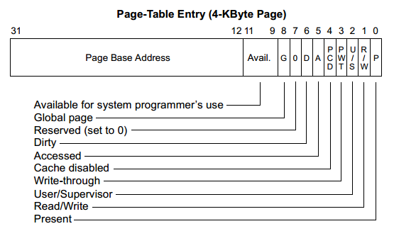
| field | significance |
|---|---|
| P | There are bits. A value of 1 indicates that the page table or page is in memory. Otherwise, it means it is not in memory |
| R/W | Read write flag. A value of 1 indicates that the page can be read and written, and a value of 0 indicates that it is read-only. When the processor is running at level 1 and 2, the privilege does not work. |
| U/S | User / super user flag. When it is 1, program access of all privilege levels is allowed; When it is 0, only programs with privilege levels of 0, 1 and 2 are allowed to access. |
| PWT | Write through flag bit of Page level. When it is 1, use the write through Cache type; The Cache type of write back is used when it is 0. When CR0 When CD = 1 (Cache is disabled), this flag is ignored. |
| PCD | Page level Cache Disable flag bit. When it is 1, the physical page cannot be cached; Allow Cache when is 0. When CR0 When CD = 1 (Cache is disabled), this flag is ignored. |
| A | Access bit. This bit is set by the processor firmware to indicate whether the page pointed to by this table item has been accessed (read or write). Once set, the processor never knows this flag bit. This bit can be used by the operating system to monitor the frequency of page usage. |
| D | Dirty bit. This bit is set by the processor firmware to indicate whether the page pointed to by this table entry has written data. |
| G | Global bit. If the page is global, it will remain in the cache. |
| Avail. | The processor can be ignored and the software can be used. |
| Page-Table Base Address | Page base address |
Taking edi=pg0, eax=0x7 as an example, the stosl instruction will write the value of eax into the es:edi memory address, that is, the first page table entry of page table 0 is set to: the page base address is 0, which allows programs of all privilege levels to access, read and write, and the page is located in memory. After that, edi points to the second page table entry of page table 0, eax=0x1007, and sets the second page table entry as: the page base address is 1, which allows programs of all privilege levels to access, read and write, and the page is located in memory. Repeat until all page table items of the 4 page tables are set.
We set the page information in the page table and the page table information in the page directory. Do we need to set the page directory information? It must be necessary. Otherwise, how does the operating system know the base address of the page directory? Where can I set the page directory information? The answer is the cr3 register. The following is the structure of cr3 register.
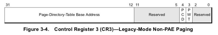
The meaning of PWT and PCD here is the same as that of PWT and PCD in the table items on the above page. page_directory_table baseaddress is the physical address, pointing to the 4KB aligned page directory address. Without using PAE technology, there are two layers of page tables (the first layer is page directory and the second layer is page table). The highest level is the page directory, with 1024 items, occupying 4KB.
Lines 80-81 set the base address of the page directory to 0.
The code in lines 82-84 sets the PG bit of CR0 to start paging.
After the ret instruction, we go to the main function.
Here is main C. contents.
#define PAGE_SIZE   4096

long user_stack[PAGE_SIZE >> 2];

struct {
	long * a;
	short b;
} stack_start = {&user_stack[PAGE_SIZE >> 2], 0x10};

void main(void)
{
	while (1);
}
The main function is relatively simple, which is an endless loop.
Let's run and have a look.
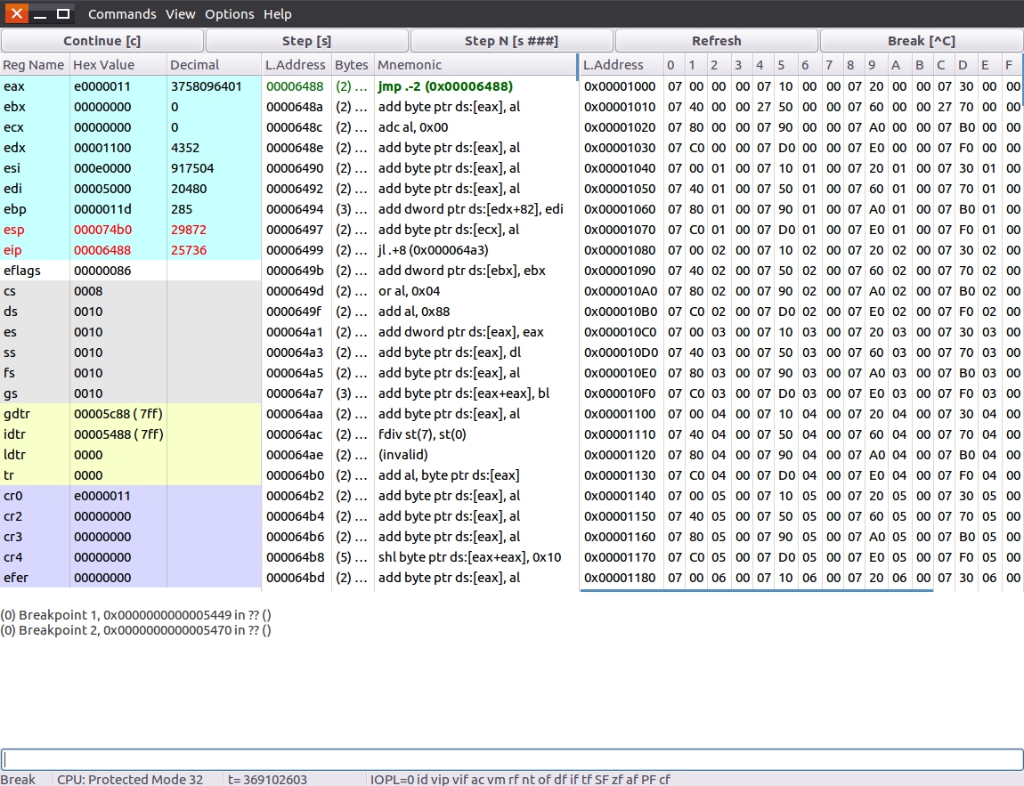
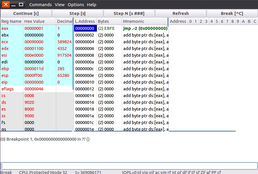
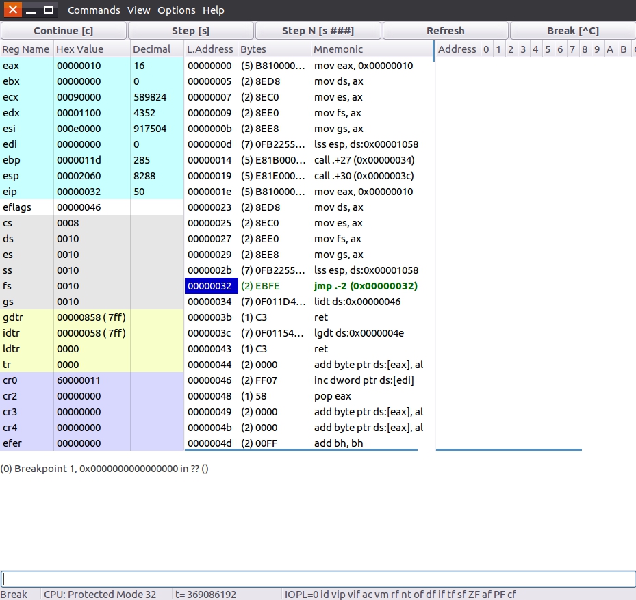
Here is the screen of running to the main function. On the right is the content of the page table. Enter 0x1000 in the menu bar view - > linear memdump... - > to view it. But wait, where can it be clearly stated that this is the main function? In the future, we will write a lot of C code. How can I know where it runs? This brings us to system Map, this file will appear after compilation. The following is the content of this section of code after compilation.
00000000 T pg_dir
00000000 T startup_32
00000000 T _text
00000047 t setup_idt
0000004f t setup_gdt
00001000 t pg0
00002000 t pg1
00003000 t pg2
00004000 t pg3
00005000 T tmp_floppy_area
00005400 t after_page_tables
00005412 t L6
00005414 t setup_paging
00005476 t idt_descr
0000547e t gdt_descr
00005488 T idt
00005c88 T gdt
00006488 T _etext
00006488 T main
000064b8 D _data
000064b8 D stack_start
000064c0 B _bss
000064c0 B _ebss
000064c0 B user_stack
000064c0 D _edata
000074c0 B _end
You can see that the address of the main function is 0x6488, which is consistent with the address on the bochs interface. Not only that, we can also see pg_dir, pg0, pg1, pg2, pg3. The files here are of great help in future debugging.
problem
1. Please write down the main context of these two chapters.
2. The code segment and data segment have the same address content in the same segment. For example, the values of cs:0x1000 and ds:0x1000 are the same. Why?
3. In Section 4, if head S line 59 JMP setup_ Change call to paging_ Paging, how do I change setup_ Can the content in paging make the program achieve the original effect?
Answers to the previous chapter
1. What are the meanings of setting segment registers in different codes?
The main purpose of setting segment register is to get the correct memory address. For example, MOV ax, the complete representation of [0] is mov ax, ds:[0]. If ds=0, put the value of 0 address into ax; if ds=0x9000, put the value of 0x90000 address into ax. In addition, some BIOS interrupts will use es, so es will be set in some places.
2. Assume setup S occupies 6 sectors. How should I modify the code?
Set bootect Set tuplen equ 4 in s to set tuplen equ 6, and DD if = boot / setup in Makefile bin of=kernel. IMG BS = 512 count = 4 seek = 1 conv = notrunc changed to DD if = boot / setup bin of=kernel. img bs=512 count=6 seek=1 conv=notrunc.
3. Change the length of gdt to 16MB, the code segment to executable only, and the base address to 0x1000. How should I change the code?
Set bootect In s, dw 0x07ff, 0x0000, 0x9a00, 0x00c0 is changed to dw 0x0fff, 0x1000, 0x9800, 0x00c0.