This article refers to cc253x system on chip solution for 2.4-GHz. If it is difficult to read English, a company has issued a Chinese translation, but some may be wrong. The English version is mainly used.
This article mainly describes the timing function of cc2530 timer 1. More functions are being updated
1. Timer 1 Introduction
Timer 1 is an independent 16 bit timer, which supports typical timing / counting functions, such as input capture, output comparison and PWM functions. The timer has 5 independent capture / comparison channels, and each channel timer uses an I/O pin. Timers are used for a wide range of control and measurement applications, with 5 channels of positive count / countdown mode available. For example, the realization of motor control application.
The functions of timer 1 are as follows:
- Five capture / compare channels
- Rising edge, falling edge or any edge sub input capture
- Set, clear, or toggle output comparison
- The counter can be run as a free running counter, a modulus counter, or a positive count / countdown.
- Clock divider divisible by 1, 8, 32 or 128
- An interrupt request is generated on each capture / comparison and final count
- DMA trigger function
2. Operating mode of timer 1
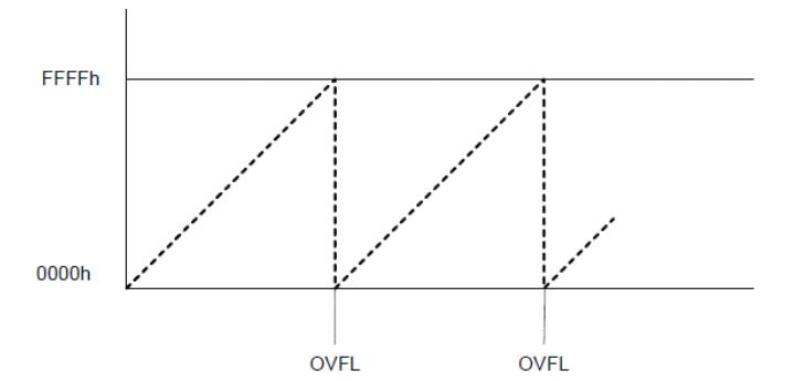
(1) Free running mode
The counter starts from 0x0000 and each active edge increases by 1. When the counter reaches 0xffff (overflow), the counter loads 0x0000 and continues to increase its value.
When the final count value 0xffff, IRCON.TIIF and T1STAT.OVFIF flag position 1, if the corresponding interrupt mask bits TIMIF.OVFIM and IEN1.T1EN are set, an interrupt request will be generated.
Free running mode can produce independent time interval and output frequency.
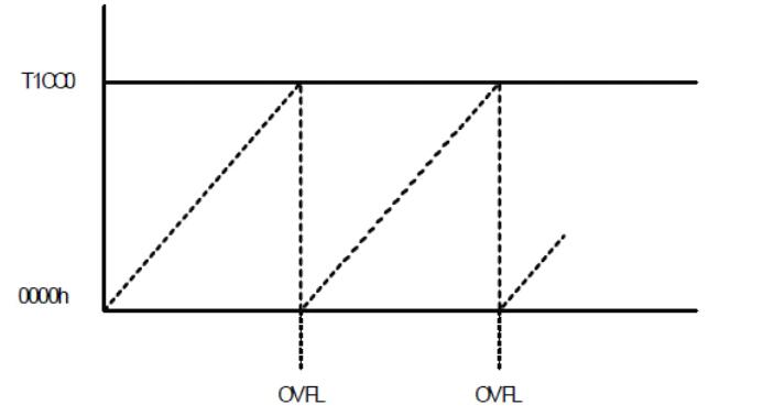
(2) Modulo mode
When the timer runs in mode, the 16 bit counter starts from 0x0000 and each active clock edge increases by 1. When the final count value stored in T1CC0 (overflow) register T1CC0H.T1CC0L is reached, the counter will be reset to 0x0000 and continue to increase.
If the timer starts with a value above T1CC0, IRCON.T1IF and T1CTL.OVFIF flag position 1 when the final count value (0xffff) is reached.
If the corresponding interrupt mask bits TIMIF.OVFIM and IEN1.T1EN are set, an interrupt request will be generated.
Modulo mode can be used for applications whose cycle is not 0xffff.
(3) Positive count / countdown mode
In the positive count / countdown mode, the counter starts from 0x0000 repeatedly, the positive count value reaches the value saved by T1CC0H:T1CC0L, and then the counter will count down until 0x0000
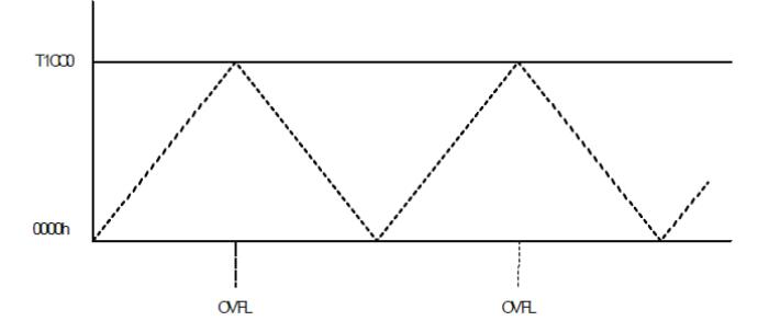
This timer is used to symmetrically output pulses, thus allowing centrally symmetrical PWM output applications to be implemented.
In the positive count / countdown mode, when the final count value is reached, the label bits IRCON.T1IF and T1CTL.OVFIF are set to 1. If the interrupt mask bits TIMIF.OVFIM and IEN1.TEN are set, an interrupt request will be generated.
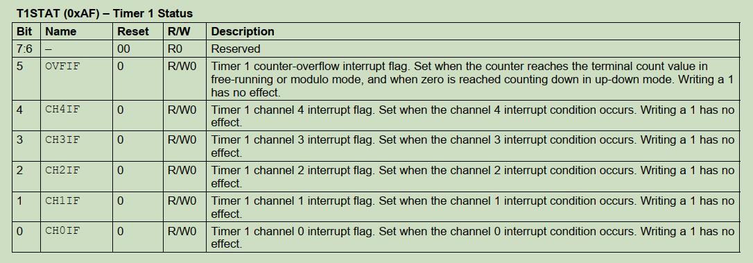
3. Timer 1 interrupt
cc2530 assigns an interrupt vector to the timer. When one of the following timer times occurs, an interrupt request is generated:
- Counter / final count value reached (overflow or return to zero)
- Input capture events
- Output comparison time (mode use)
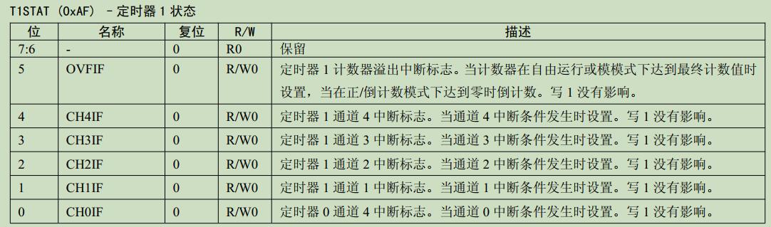
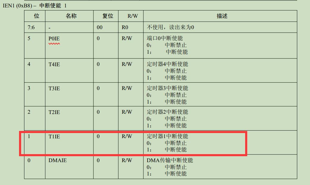
Note: the register T1STAT contains the interrupt flag of the final count event and the five sum interrupt comparison capture event. The interrupt request can be generated only when IEN1.T1EN is set.
4. Timer 1 timing routine
It should be noted that:
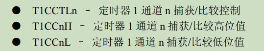
- Timer 1 has 5 rows of T1CCnH and T1CCnL registers, corresponding to channel 0 to channel 4 respectively. When using the timing function of timer 1, it is necessary to use the high 8 bits and low 8 bits of the maximum count values of T1CC0H and T1CC0L. See cc253x system on chip solution for 2.4-GHz for details.
- When the system does not configure the working frequency, the default is 2 frequency division, the external crystal oscillator is 32MHZ, and the system clock is 16MHZ
(1) The query mode uses timer 1
#include <iocc2530.h>

#define uint unsigned int
#define uchar unsigned char

//Defines the port that controls the LED lights
#define LED1 P1_0

//LED initialization
void InitLED(void)
{
  P1DIR |= 0x03;  //Define P1_0 is output
  LED1 = 1;       //LED1 off
}

//System clock initialization
//Set the system clock to 32MHZ
void systemClockInit(void)
{
  CLKCONCMD &= ~0x40;//Set the system clock source to 32MHZ crystal oscillator
  while(CLKCONCMD & 0x40);//Wait for the crystal oscillator to stabilize
  CLKCONCMD &= ~0x47;//Set the system master clock frequency to 32MHZ
}

//Timer T1 initialization
void InitT1(void)
{
  //The system does not configure the working clock mode, and the default frequency division is 2
  //Free running, 128 frequency division
  T1CTL = 0x0d;

  //Channel 0, interrupt valid t = 1 / (16000000 / 128) * 65535
  //About 0.524s delay
  T1STAT = 0x21;
}

void main(void)
{
  uchar count = 0;
  InitLED();
  systemClockInit();
  InitT1();
  while(1)
  {
    if(IRCON > 0)//System counter to
    {
      IRCON = 0;//Counter reset
      count++;
      if(count >= 1)
      {
        count = 0;//Count reset
        LED1 = !LED1;//LED flashing
      }
    }
  }
}
(2) Interrupt mode using timer 1
#include <iocc2530.h>

#define uint unsigned int
#define uchar unsigned char

//Defines the port that controls the LED lights
#define LED1 P1_0

//Global variable definition
uchar count = 0;

//LED initialization
void InitLED(void)
{
  P1DIR |= 0x03;  //Define P1_0 is output
  LED1 = 1;       //LED1 off
}

//System clock initialization
//Set the system clock to 32MHZ
void systemClockInit(void)
{
  CLKCONCMD &= ~0x40;//Set the system clock source to 32MHZ crystal oscillator
  while(CLKCONCMD & 0x40);//Wait for the crystal oscillator to stabilize
  CLKCONCMD &= ~0x47;//Set the system master clock frequency to 32MHZ
}

//Timer T1 initialization
void InitT1(void)
{
  //The system does not configure the working clock mode, and the default frequency division is 2
  //Free running, 128 frequency division
  T1CTL = 0x0d;

  //Channel 0, interrupt valid t = 1 / (16000000 / 128) * 65535
  //About 0.524s delay
  T1STAT = 0x21;
  T1IE = 1;//On timer 1 interrupt
  EA = 1;//On total interrupt
}

void main(void)
{
  InitLED();
  systemClockInit();
  InitT1();
  while(1);
}

#pragma vector = T1_VECTOR
__interrupt void T1_ISR(void)
{
    IRCON = 0;//Please zero the counter
    count++;
    if(count >= 1)
    {
      count = 0;//Count reset
      LED1 = !LED1;//LED flashing
    }
}
(3) Timer 1 mode
#include <iocc2530.h>

#define uint unsigned int
#define uchar unsigned char

//Constant macro definition
#Define FOSC 32000000 / / macro definition clock
#define SET_ Time 0.01 / / timing time (s)
#define FREQUENCY_ DIVISION_ Num 128 / / frequency division coefficient


//Defines the port that controls the LED lights
#define LED1 P1_0

//Global variable definition
uint count = 0;

//LED initialization
void InitLED(void)
{
  P1DIR |= 0x03;  //Define P1_0 is output
  LED1 = 1;       //LED1 off
}

//System clock initialization
//Set the system clock to 32MHZ
void systemClockInit(void)
{
  CLKCONCMD &= ~0x40;//Set the system clock source to 32MHZ crystal oscillator
  while(CLKCONCMD & 0x40);//Wait for the crystal oscillator to stabilize
  CLKCONCMD &= ~0x47;//Set the system master clock frequency to 32MHZ
}

//Timer T1 initialization_ Modular mode
//
//Analog mode requires the output comparison mode of channel 0 to be turned on
//Otherwise, the counter will generate overflow interrupt (corresponding overflow flag) only when it reaches 0XFF
//That is, if the output comparison mode of channel 0 is not set
//After the counter value reaches T1CC0, no overflow interrupt will be generated (the corresponding overflow flag will not be set to 1)
//This requires special attention.
//
void InitT1_Modulo(void)
{
  //timer1 128 frequency division, mode
  T1CTL = 0x0e;

  //Set timer1 channel 0 output comparison mode
  T1CCTL0 |= 0x04;

  //Calculate the maximum count value
  uint maximum_count = (SET_TIME * FOSC)/FREQUENCY_DIVISION_NUM;

  T1CC0H = maximum_count/256;
  T1CC0L = maximum_count%256;

  //timer1 overflow interrupt mask
  TIMIF |= 0X40;

  //Enable timer1 interrupt
  IEN1 |= 0x02;

  //Clear interrupt flag
  IRCON &= ~0x02;
  T1STAT &= ~0x01;

  //On total interrupt
  EA = 1;
}

void main(void)
{
  InitLED();
  systemClockInit();
  InitT1_Modulo();
  while(1);
}

#pragma vector = T1_VECTOR
__interrupt void T1_ISR(void)
{
  count++;
  if(count == 50)//Timing 500ms
  {
    LED1 = !LED1;
    count = 0;
  }

  //Clear interrupt flag
  IRCON &= ~0x02;
  T1STAT &= ~0x01;
}
(3) Timer 1 positive count / countdown mode
This mode is mainly used for cycle or PWM output. It has little significance for timing. You can choose free mode or mode for timing.
CC2530 outputs PWM and frequency, which will be updated later