reference material:
https://blog.csdn.net/zhaoxinfan/article/details/54958641
https://blog.csdn.net/asmartkiller/article/details/84072643
https://blog.csdn.net/qq_40155300/article/details/89001808
SDK version: April 2017
Write before:
This document is not enough to make you clear the register level operation details of FSBL startup, but it can let you see the main process of the execution of the whole ZYNQ7000 FSBL code.
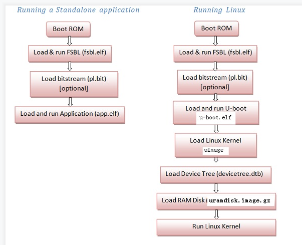
1. ZYNQ7000 loading and starting process
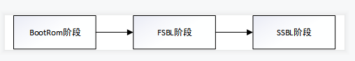
(1) The BootRom stage is the code loaded the earliest after the ARM is powered on. Confirm the loading mode according to the MIO pin configuration, initialize the corresponding startup medium, load the FSBL into the OCM, and hand over the control to the FSBL
(2) FSBL stage completes PS initialization, loads PL bit stream file, and loads SSBL boot program or bare metal program of ARM
(3) The SSBL stage is divided into two situations: ① the bare metal program is directly executed in the DDR; ② the process of loading the kernel under uboot boot
2. FSBL code analysis
(1) In file FSBL_bsp/standalone_v6_5/src/asm_ventors.S, a code snippet is declared at address 0. After power on, the PS automatically executes the instruction at address 0, and the first line of code is a jump: B_ boot
.org 0
.text

.globl _vector_table

.section .vectors
_vector_table:
	B	_boot
	B	Undefined
	B	SVCHandler
	B	PrefetchAbortHandler
	B	DataAbortHandler
	NOP	/* Placeholder for address exception vector*/
	B	IRQHandler
	B	FIQHandler
(2) Find the file boot. In the same directory It can be seen in S_ The code under the boot label_ Boot will do a series of initialization for the system, including DDR, interrupt, MMU, cache, etc. after execution, PS will have the ability to execute C code.
You can see in_ The boot code finally performs another jump: B_ start
	b	_start				/* jump to C startup code */
	and	r0, r0, r0			/* no op */
(3) Find the file xil-crt0.0 in the same directory It can be seen in S_ The code under the start label can be seen_ Start first performs a jump: bl__ cpu_ Init to perform CPU initialization
_start:
	bl      __cpu_init		/* Initialize the CPU first (BSP provides this) */

	mov	r0, #0

	/* clear sbss */
	ldr 	r1,.Lsbss_start		/* calculate beginning of the SBSS */
	ldr	r2,.Lsbss_end		/* calculate end of the SBSS */
(4) In_ At the end of the start label code, you can see that bsp has completed all the initialization work and will jump to the main function to start execution.
	/* make sure argc and argv are valid */
	mov	r0, #0
	mov	r1, #0

	/* Let her rip */
	bl	main
(5) Back to the FSBL project, in the directory FSBL / SRC / main Find the main function in C, and you can see that the first step is to call ps7_init() function.
ps7_ The init() function is located in ps7_init.c file, which is automatically generated by XPS according to the user's configuration.
View ps7_init() function. It is obvious from the code that this function actually performs the initialization of MIO, PLL, CLK, DDR and other peripherals according to the PS version.
int main(void)
{
	u32 BootModeRegister = 0;
	u32 HandoffAddress = 0;
	u32 Status = XST_SUCCESS;

	/*
	 * PCW initialization for MIO,PLL,CLK and DDR
	 */
	Status = ps7_init();
	if (Status != FSBL_PS7_INIT_SUCCESS) {
		fsbl_printf(DEBUG_GENERAL,"PS7_INIT_FAIL : %s\r\n",
						getPS7MessageInfo(Status));
		OutputStatus(PS7_INIT_FAIL);
		/*
		 * Calling FsblHookFallback instead of Fallback
		 * since, devcfg driver is not yet initialized
		 */
		FsblHookFallback();
	}
int
ps7_init()
{
// Get the PS_VERSION on run time
unsigned long si_ver = ps7GetSiliconVersion ();
int ret;
//int pcw_ver = 0;
if (si_ver == PCW_SILICON_VERSION_1) {
ps7_mio_init_data = ps7_mio_init_data_1_0;
ps7_pll_init_data = ps7_pll_init_data_1_0;
ps7_clock_init_data = ps7_clock_init_data_1_0;
ps7_ddr_init_data = ps7_ddr_init_data_1_0;
ps7_peripherals_init_data = ps7_peripherals_init_data_1_0;
//pcw_ver = 1;
} else if (si_ver == PCW_SILICON_VERSION_2) {
ps7_mio_init_data = ps7_mio_init_data_2_0;
ps7_pll_init_data = ps7_pll_init_data_2_0;
ps7_clock_init_data = ps7_clock_init_data_2_0;
ps7_ddr_init_data = ps7_ddr_init_data_2_0;
ps7_peripherals_init_data = ps7_peripherals_init_data_2_0;
//pcw_ver = 2;
} else {
ps7_mio_init_data = ps7_mio_init_data_3_0;
ps7_pll_init_data = ps7_pll_init_data_3_0;
ps7_clock_init_data = ps7_clock_init_data_3_0;
ps7_ddr_init_data = ps7_ddr_init_data_3_0;
ps7_peripherals_init_data = ps7_peripherals_init_data_3_0;
//pcw_ver = 3;
}
// MIO init
ret = ps7_config (ps7_mio_init_data);
if (ret != PS7_INIT_SUCCESS) return ret;
// PLL init
ret = ps7_config (ps7_pll_init_data);
if (ret != PS7_INIT_SUCCESS) return ret;
// Clock init
ret = ps7_config (ps7_clock_init_data);
if (ret != PS7_INIT_SUCCESS) return ret;
// DDR init
ret = ps7_config (ps7_ddr_init_data);
if (ret != PS7_INIT_SUCCESS) return ret;
// Peripherals init
ret = ps7_config (ps7_peripherals_init_data);
if (ret != PS7_INIT_SUCCESS) return ret;
//xil_printf ("\n PCW Silicon Version : %d.0", pcw_ver);
return PS7_INIT_SUCCESS;
}(6) System Software Reset to enable the System Software Reset function
/*
	 * Unlock SLCR for SLCR register write
	 */
	SlcrUnlock();
(7) Turn off cache function
/*
	 * Flush the Caches
	 */
	Xil_DCacheFlush();

	/*
	 * Disable Data Cache
	 */
	Xil_DCacheDisable();
(8) Abnormal interruption of registration
/*
	 * Register the Exception handlers
	 */
	RegisterHandlers();
This is equivalent to all exception handling functions pointing to the 0 address.
Xil_ExceptionRegisterHandler(XIL_EXCEPTION_ID_UNDEFINED_INT,
					(Xil_ExceptionHandler)Undef_Handler,
					(void *) 0);
	XExc_VectorTable[Exception_id].Handler = Handler;
	XExc_VectorTable[Exception_id].Data = Data;
(9) DDR read-write test, read-write comparison in different DDR address segments
   /*
     * DDR Read/write test
     */
	Status = DDRInitCheck();
	if (Status == XST_FAILURE) {
		fsbl_printf(DEBUG_GENERAL,"DDR_INIT_FAIL \r\n");
		/* Error Handling here */
		OutputStatus(DDR_INIT_FAIL);
		/*
		 * Calling FsblHookFallback instead of Fallback
		 * since, devcfg driver is not yet initialized
		 */
		FsblHookFallback();
	}
(10) Processor Configuration Access Port is the processor configuration interface, which is the bridge between software and hardware.
	/*
	 * PCAP initialization
	 */
	Status = InitPcap();
	if (Status == XST_FAILURE) {
		fsbl_printf(DEBUG_GENERAL,"PCAP_INIT_FAIL \n\r");
		OutputStatus(PCAP_INIT_FAIL);
		/*
		 * Calling FsblHookFallback instead of Fallback
		 * since, devcfg driver is not yet initialized
		 */
		FsblHookFallback();
	}

	fsbl_printf(DEBUG_INFO,"Devcfg driver initialized \r\n");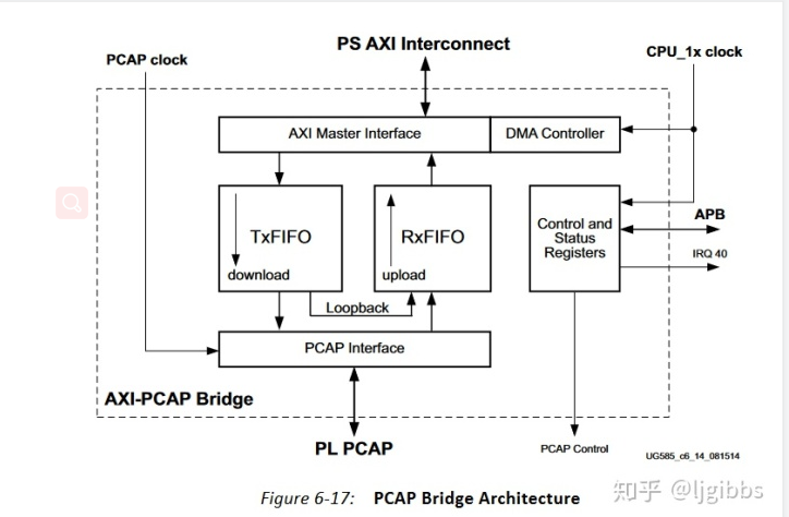
(11) Get PS version number
/*
	 * Get the Silicon Version
	 */
	GetSiliconVersion();
(12) Obtain the configuration information of PCAP interface controller and check whether system reset is allowed
	/*
	 * Get PCAP controller settings
	 */
	PcapCtrlRegVal = XDcfg_GetControlRegister(DcfgInstPtr);

	/*
	 * Check for AES source key
	 */
	if (PcapCtrlRegVal & XDCFG_CTRL_PCFG_AES_FUSE_MASK) {
		/*
		 * For E-Fuse AES encryption Watch dog Timer disabled and
		 * User not allowed to do system reset
		 */
#ifdef	XPAR_XWDTPS_0_BASEADDR
		fsbl_printf(DEBUG_INFO,"Watchdog Timer Disabled\r\n");
		XWdtPs_Stop(&Watchdog);
#endif
		fsbl_printf(DEBUG_INFO,"User not allowed to do "
								"any system resets\r\n");
	}
(13) Configure FSBL execution status
	/*
	 * Store FSBL run state in Reboot Status Register
	 */
	MarkFSBLIn();
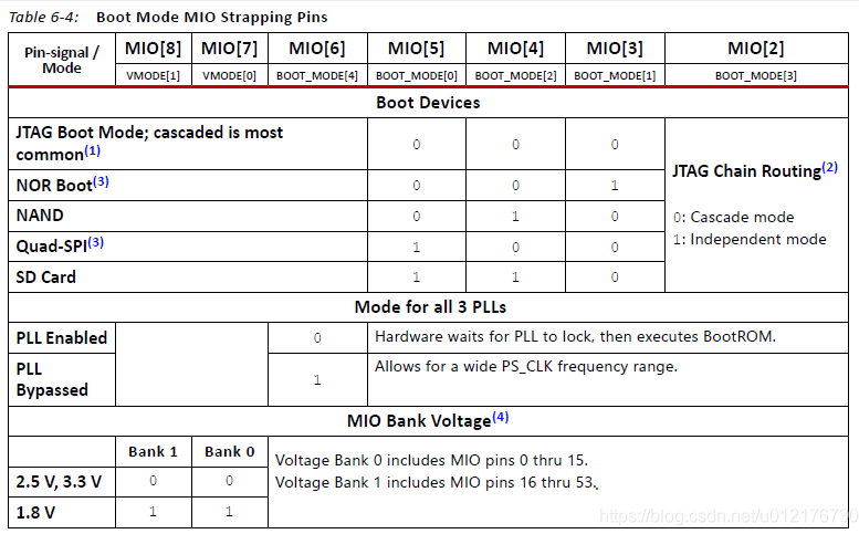
(14) Read the startup mode register. The startup mode is configured through the MIO pin. To configure the corresponding startup mode, refer to the configuration of each MIO pin in different modes in the figure below
/*
	 * Read bootmode register
	 */
	BootModeRegister = Xil_In32(BOOT_MODE_REG);
	BootModeRegister &= BOOT_MODES_MASK;
(15) Initialize the corresponding storage device according to the startup mode
QSPI start
① Initialize qspi Flash
②MoveImage = QspiAccess; Function pointer assignment to copy image from Norflash to memory
	if (BootModeRegister == QSPI_MODE) {
		fsbl_printf(DEBUG_GENERAL,"Boot mode is QSPI\n\r");
		InitQspi();
		MoveImage = QspiAccess;
		fsbl_printf(DEBUG_INFO,"QSPI Init Done \r\n");
Norlflash start
	/*
	 * NOR BOOT MODE
	 */
	if (BootModeRegister == NOR_FLASH_MODE) {
		fsbl_printf(DEBUG_GENERAL,"Boot mode is NOR\n\r");
		/*
		 * Boot ROM always initialize the nor at lower speed
		 * This is the chance to put it to an optimum speed for your nor
		 * device
		 */
		InitNor();
		fsbl_printf(DEBUG_INFO,"NOR Init Done \r\n");
		MoveImage = NorAccess;
JTAG start
	/*
	 * JTAG  BOOT MODE
	 */
	if (BootModeRegister == JTAG_MODE) {
		fsbl_printf(DEBUG_GENERAL,"Boot mode is JTAG\r\n");
		/*
		 * Stop the Watchdog before JTAG handoff
		 */
#ifdef	XPAR_XWDTPS_0_BASEADDR
		XWdtPs_Stop(&Watchdog);
#endif
		/*
		 * Clear our mark in reboot status register
		 */
		ClearFSBLIn();

		/*
		 * SLCR lock
		 */
		SlcrLock();

		FsblHandoffJtagExit();
(16) FlashReadBaseAddress is initialized according to different startup devices in the above process.
Normally, we use Norflash to start, and the InitQspi() function will assign a value to FlashReadBaseAddress, that is, the starting address of QSPI false is 0xFC000000, which can be seen in the data manual UG585 of zynq7000.
	/*
	 * Check for valid flash address
	 */
	if ((FlashReadBaseAddress != XPS_QSPI_LINEAR_BASEADDR) &&
			(FlashReadBaseAddress != XPS_NAND_BASEADDR) &&
			(FlashReadBaseAddress != XPS_NOR_BASEADDR) &&
			(FlashReadBaseAddress != XPS_SDIO0_BASEADDR)) {
		fsbl_printf(DEBUG_GENERAL,"INVALID_FLASH_ADDRESS \r\n");
		OutputStatus(INVALID_FLASH_ADDRESS);
		FsblFallback();
	}

	/*
	 * NOR and QSPI (parallel) are linear boot devices
	 */
	if ((FlashReadBaseAddress == XPS_NOR_BASEADDR)) {
		fsbl_printf(DEBUG_INFO, "Linear Boot Device\r\n");
		LinearBootDeviceFlag = 1;
	}
(17) Next is the key point. This function does two things: ① analyze the header of the data burned into qspi, and ② copy the data to DDR according to the analysis results
	/*
	 * Load boot image
	 */
	HandoffAddress = LoadBootImage();

	fsbl_printf(DEBUG_INFO,"Handoff Address: 0x%08lx\r\n",HandoffAddress);
(18) We go to the function LoadBootImage() to further analyze the code
The function of this code is to read the address of the image to be executed from the multiboot register. In fact, if there is only one image, you can ignore this. The calculated imagestartaddress must be 0
	/*
		 * read the multiboot register
		 */
		MultiBootReg =  XDcfg_ReadReg(DcfgInstPtr->Config.BaseAddr,
				XDCFG_MULTIBOOT_ADDR_OFFSET);

		fsbl_printf(DEBUG_INFO,"Multiboot Register: 0x%08lx\r\n",MultiBootReg);

		/*
		 * Compute the image start address
		 */
		ImageStartAddress = (MultiBootReg & PCAP_MBOOT_REG_REBOOT_OFFSET_MASK)
									* GOLDEN_IMAGE_OFFSET;
(19) Parse Image, i.e. boot Header information of bin
① Parse boot. From bootloader Bin size (this information is not used later)
② Put the boot The header in Bin parses the partition header and saves it to the global variable partitionheader [max_partition_number]. There are only three valid partitions, namely fsbl elf,FPGA.bit,application.elf
③ The number of partitions parsed according to the parsed partition header data
	/*
	 * Get partitions header information
	 */
	Status = GetPartitionHeaderInfo(ImageStartAddress);
	if (Status != XST_SUCCESS) {
		fsbl_printf(DEBUG_GENERAL, "Partition Header Load Failed\r\n");
		OutputStatus(GET_HEADER_INFO_FAIL);
		FsblFallback();
	}
PartHeader is boot Header information structure of each partition parsed in Bin
typedef struct StructPartHeader {
	u32 ImageWordLen;	/* 0x0 */
	u32 DataWordLen;	/* 0x4 */
	u32 PartitionWordLen;	/* 0x8 */
	u32 LoadAddr;		/* 0xC */
	u32 ExecAddr;		/* 0x10 */
	u32 PartitionStart;	/* 0x14 */
	u32 PartitionAttr;	/* 0x18 */     // Used to determine file attributes, such as FPGA Bit file or application ELF file
	u32 SectionCount;	/* 0x1C */
	u32 CheckSumOffset;	/* 0x20 */
	u32 Pads1[1];
	u32 ACOffset;	/* 0x28 */
	u32 Pads2[4];
	u32 CheckSum;		/* 0x3C */
}PartHeader;
We need to know here BOOT.bin Structure of. stay boot.bin From address 0-0x8BF It can be divided into 17 parts, and each part has a certain meaning 1. 0x000 Interrupt vector table 2. 0x020 Fixed value 0 xaa995566 3. 0x024 Fixed value 0 x584c4e58 ASCII: XLNX 4. 0x028 If 0 xa5c3c5a3 Or 0 x3a5c3c5a Encrypted for 5. 0x02C bootrom Head version number, never mind 6. 0x030 from bootrom Start to app Total number of addresses( bytes) 7. 0x034 from loadimage Copy to OCM Length [after power on BootRom Will take the initiative to FSBL copy to OCM [execute in] 8. 0x038 Where to copy the destination address FSBL 9. 0x03C Address to start execution 10. 0x040 The same as 7 [the code logic here actually assigns the value of this field to FSBL of size] 11. 0x044 0x01 Is a fixed value 12. 0x048 Checksum (from 0) x020-0x047)Press 32-bit word Additive negation 13. 0x04C bootgen relevant 14. 0x098 image Table pointer of header 15. 0x09C partition Table pointer of header 16. 0x0A0 Parameters for register initialization 17. 0x8A0 fsbl user defined 18. 0x8C0 fsbl Where to start
(20) After you get the partition header, you should load each partition separately. However, since the 0 partition is actually FSBL, and we are actually executing FSBL, you don't need to load it. Skip loading from partitionNum = 1
	/*
	 * First partition header was ignored by FSBL
	 * As it contain FSBL partition information
	 */
	PartitionNum = 1;
(21) next, start loading, which is similar to each partition. It mainly completes two parts:
① Parse and check the correctness of the contents in each partition header
② Load each Parton from norflash to the specified destination address. (there are differences between FPGA.bit and application.elf)
Judge whether it is a bit file or an application file according to the attribute in the partition header
		if (PartitionAttr & ATTRIBUTE_PL_IMAGE_MASK) {
			fsbl_printf(DEBUG_INFO, "Bitstream\r\n");
			PLPartitionFlag = 1;
			PSPartitionFlag = 0;
			BitstreamFlag = 1;
		}

		if (PartitionAttr & ATTRIBUTE_PS_IMAGE_MASK) {
			fsbl_printf(DEBUG_INFO, "Application\r\n");
			PSPartitionFlag = 1;
			PLPartitionFlag = 0;
			ApplicationFlag = 1;
		}
This function moves partition data to DDR
	/*
		 * Move partitions from boot device
		 */
		Status = PartitionMove(ImageStartAddress, HeaderPtr);
		if (Status != XST_SUCCESS) {
			fsbl_printf(DEBUG_GENERAL,"PARTITION_MOVE_FAIL\r\n");
			OutputStatus(PARTITION_MOVE_FAIL);
			FsblFallback();
		}
FPGA.bit and application Elf files are sequentially moved and transferred to DDR through the following functions
if ((LinearBootDeviceFlag && PLPartitionFlag &&
			(SignedPartitionFlag || PartitionChecksumFlag)) ||
				(LinearBootDeviceFlag && PSPartitionFlag) ||
				((!LinearBootDeviceFlag) && PSPartitionFlag && SecureTransferFlag)) {
		/*
		 * PL signed partition copied to DDR temporary location
		 * using non-secure PCAP for linear boot device
		 */
		if(PLPartitionFlag){
			SecureTransferFlag = 0;
			LoadAddr = DDR_TEMP_START_ADDR;
		}

		/*
		 * Data transfer using PCAP
		 */
		Status = PcapDataTransfer((u32*)SourceAddr,
						(u32*)LoadAddr,
						ImageWordLen,
						DataWordLen,
						SecureTransferFlag);
		if(Status != XST_SUCCESS) {
			fsbl_printf(DEBUG_GENERAL, "PCAP Data Transfer Failed\r\n");
			return XST_FAILURE;
		}
(22) if the partition is an FPGA bit file, load the startup bit file from DDR through the following function. This function involves the operation process of PCAP, which will not be explored here.
/*
			 * Load Signed PL partition in Fabric
			 */
			if (PLPartitionFlag) {
				Status = PcapLoadPartition((u32*)PartitionStartAddr,
						(u32*)PartitionLoadAddr,
						PartitionImageLength,
						PartitionDataLength,
						EncryptedPartitionFlag);
				if (Status != XST_SUCCESS) {
					fsbl_printf(DEBUG_GENERAL,"BITSTREAM_DOWNLOAD_FAIL\r\n");
					OutputStatus(BITSTREAM_DOWNLOAD_FAIL);
					FsblFallback();
				}
			}
(23) so far, the function LoadBootImage has been fully executed, and the FPGA has been completed Bit is loaded, and the application has been written to the DDR.
In the following function, handofaddress should be the execution address in the application partition header, which is also the application Elf base address saved in DDR, i.e. 0x00100000
	/*
	 * FSBL handoff to valid handoff address or
	 * exit in JTAG
	 */
	FsblHandoff(HandoffAddress);
In this function, FSBL to application is implemented through FsblHandoffExit(FsblStartAddr) function Jump of ELF
if(FsblStartAddr == 0) {
		/*
		 * SLCR lock
		 */
		SlcrLock();

		fsbl_printf(DEBUG_INFO,"No Execution Address JTAG handoff \r\n");
		FsblHandoffJtagExit();
	} else {
		fsbl_printf(DEBUG_GENERAL,"SUCCESSFUL_HANDOFF\r\n");
		OutputStatus(SUCCESSFUL_HANDOFF);
		FsblHandoffExit(FsblStartAddr);
	}
In Src / fsbl_ handoff. In the s file, the bx lr instruction jumps to the application to start execution
FsblHandoffExit:
		mov	 lr, r0	/* move the destination address into link register */

		mcr	 15,0,r0,cr7,cr5,0		/* Invalidate Instruction cache */
		mcr	 15,0,r0,cr7,cr5,6		/* Invalidate branch predictor array */

		dsb
		isb					/* make sure it completes */

	ldr	r4, =0
		mcr	 15,0,r4,cr1,cr0,0		/* disable the ICache and MMU */

		isb					/* make sure it completes */


		bx		lr	/* force the switch, destination should have been in r0 */

.Ldone: b		.Ldone					/* Paranoia: we should never get here */
.end
(24) the above FSBL runs and loads FPGA Bit and boot application Elf execution process code analysis is completed.