Introduction to Internet of things and communication module
Embedded Internet of things: ARM architecture certification, Huawei Internet of things certification, Ministry of industry and information technology
Communication technology of Internet of things: wired communication Ethernet
OSI7 layer network structure:
- Application layer: the final port of network service
- Presentation layer: the binary data in the data packet can be converted into data in different formats
- Session layer: establish, manage and terminate sessions, and distinguish different sessions according to different systems and platforms
- Transport layer: defines the protocol port number and flow control of data transmission, such as TCP/UDP
- Network layer: it realizes the path selection between different networks, such as data packets, routing
- Data link layer: it can be divided into two layers
LLC: it is a logical link control that interacts with the network layer
MAC: the content of the physical layer is processed by the MAC and the media access control - Physical layer: establish, maintain and disconnect physical connections (defining digital signals or analog signals required for data transmission and reception)
(line status, clock calibration, data coding) (and provide standard interfaces to the data link layer)
RS232 and RS485 are widely used in the industrial Internet of things
M-BUS can not only transmit data, but also supply power
PLC power line communication
Wireless communication: short-range wireless communication, cellular mobile network, low-power wide area network
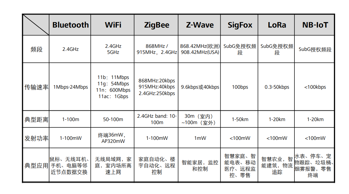
Short range wireless communication:
| Bluetooth | WiFi | ZigBee | Z-Wave |
|---|---|---|---|
| Suitable for short-range wireless communication | Component public WiFi or commercial WiFi | Wireless communication technology with short distance and low power consumption | Emerging short-range wireless communication technology based on RF, low cost, low power consumption, high reliability and suitable for network. |
| The carrier frequency is 2.4GHz and the transmission speed is 1Mbps | Carrier frequency 2.4GHz or 5GHz | ||
| Its transmission distance is about 10cm-10m, and the power amplifier can be added | |||
| Advantages: high speed, low power consumption and high safety | Advantages: wide coverage and fast data transmission rate. | It is characterized by short distance, low complexity, self-organization, low power consumption | Advantages: simple structure, low rate, low power consumption, low cost and high reliability. |
| Disadvantages: there are few network nodes, which is not suitable for multi-point control | Poor transmission security, poor stability, slightly higher power consumption and poor networking capability | Low data rate. | Disadvantages: standards are not open, |
Cellular mobile network: 2G, 3G, 4G and 5g, three application scenarios, enhanced mobile Internet, ultra-high reliability and ultra-low delay services, and massive IOT services
Cellular mobile network is called cellular mobile network because the coverage of communication base station signals constituting network coverage presents a hexagon, like a cell
Main components of cellular mobile network:
- Mobile station: network terminal equipment (mobile tablet industrial control equipment)
- Base station subsystem: it is a common base station (big tower)
- Network subsystem: it is the control and switching center of the whole cellular mobile network
Wireless communication module:
- Own LAN: Bluetooth, ZigBee, Nrf
- Connect to cloud platform: WiFi, GPRS, Nb IOT The country does not standardize the IOT network card (very cheap) and poor signal
Embedded Internet of things:
Nrf module
Nrf24L01 is a 2.4GHz~2.5GHz radio frequency module, and 2.4GHz~2.5GHz is the carrier frequency
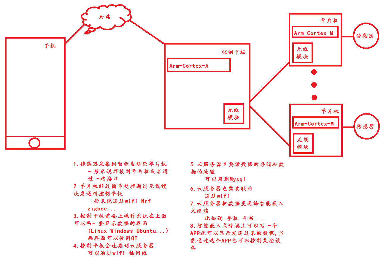
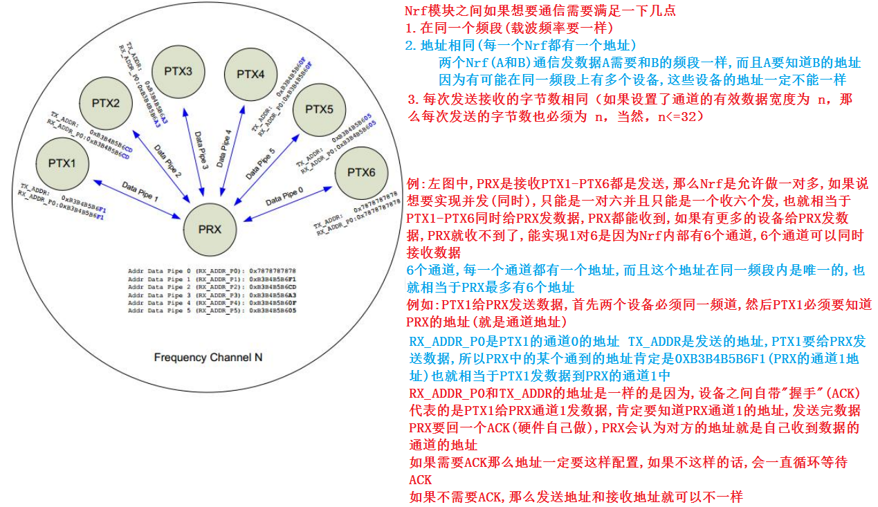
Nrf communication framework:
Nrf hardware diagram:
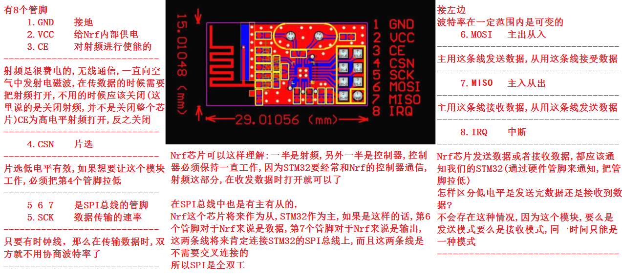
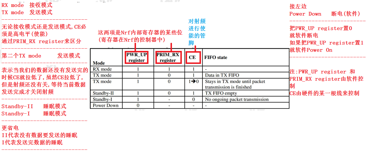
Nrf operating mode:
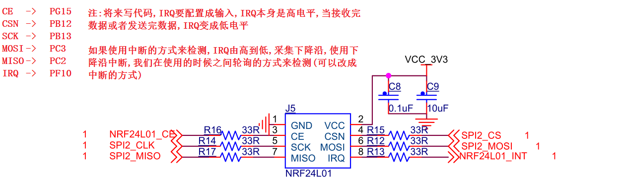
Nrf hardware schematic diagram:
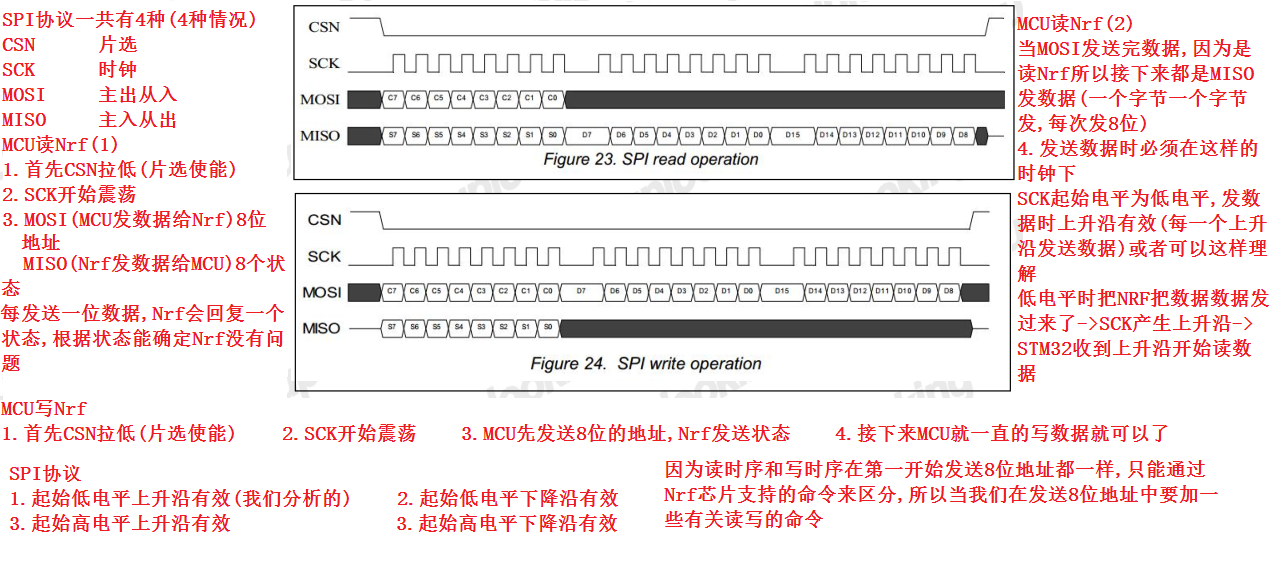
SPI protocol:
Nrf code driven
nrf2401.h
#ifndef __SPI_NRF_H__
#define __SPI_NRF_H__
/*
Development board equipment 		 Connected pins
CE						PC5
CSN						PC4
SCK						PA7
MOSI					PA6
MISO					PA5
IRQ						PA4
 It is known that the pins of the chip are multifunctional reusable pins
 The pins of the chip will have input function, output function, multiplexing function and analog function
 This time we operate the wireless communication module Nrf24L01 on the development board
 It is known that the interface of the module is SPI interface. We need to connect the module to the pin with SPI interface
 However, in order to consider the portability, we still use GPIO to simulate SPI protocol
*/
#include "stm32f10x_conf.h" / / this header file is included. All peripheral header files have been included
//Allow communication between Nrf modules (send data < = 32 bytes at a time)
//Use the following structure (32 bytes) for communication
//The meaning of the members has the final say.
struct nrf_msg_st//The structure of the defined send packet (no more than 32 bytes)
{
	u32 Dht_Hum;//Humidity of storage DHT11
	u32 Dht_Temp;//Temperature of storage DHT11
	float Sht_Temp;//Temperature of storage SHT30
	float Sht_Hum;//Humidity of storage SHT30
	u8 buf[16];//Store other data
};
//Simulate SPI bus with GPIO (good portability)
//This part needs to be modified during code migration (open the hardware schematic)
//This can also be modified to bit band operation
#define NRF_CSN_HIGH()      GPIO_SetBits(GPIOC, GPIO_Pin_4) / / the chip selection is raised (the device cannot be operated)
#define NRF_CSN_LOW()       	 GPIO_ResetBits(GPIOC, GPIO_Pin_4) / / lower the chip selection (you can operate the device)
#define NRF_CE_HIGH() 	   		 GPIO_SetBits(GPIOC, GPIO_Pin_5) / / pull up Ce (turn on RF)
#define NRF_CE_LOW() 	   		 GPIO_ResetBits(GPIOC, GPIO_Pin_5) / / pull down Ce (turn off RF)
#define NRF_Read_IRQ() 			 GPIO_ReadInputDataBit(GPIOA, GPIO_Pin_4) / / the pin of the read interrupt (whether sending or receiving data is low level)

#define NRF_MOSI_HIGH() 			 GPIO_SetBits(GPIOA, GPIO_Pin_6)//MOSI pull up
#define NRF_MOSI_LOW() 			 GPIO_ResetBits(GPIOA, GPIO_Pin_6)//MOSI pull down
#define NRF_CLK_HIGH() 			 GPIO_SetBits(GPIOA, GPIO_Pin_7)//CLK pull up
#define NRF_CLK_LOW() 				 GPIO_ResetBits(GPIOA, GPIO_Pin_7)//CLK pull down
#define NRF_Read_MISO() 			 GPIO_ReadInputDataBit(GPIOA, GPIO_Pin_5) / / read miso (Master in slave out)

#define TX_ADR_WIDTH  		 five 	// Transmit address width (5 bytes)

#define RX_ADR_WIDTH    5 		// Each Nrf will have an address (3, 4, 5 bytes)

// SPI(nRF24L01) commands
#define NRF_READ_REG    0x00  // Define read command to register
#define NRF_WRITE_REG   0x20  // Define write command to register
#define RD_RX_PLOAD 		0x61  // Define RX payload register address
#define WR_TX_PLOAD 		0xA0  // Define TX payload register address
#define FLUSH_TX    		0xE1  // Define flush TX register command
#define FLUSH_RX    		0xE2  // Define flush RX register command
#define REUSE_TX_PL 		0xE3  // Define reuse TX payload register command
#define NOP         		0xFF  // Define No Operation, might be used to read status register

// SPI(nRF24L01) registers(addresses)
#define CONFIG      		0x00  // 'Config' register address
#define EN_AA       		0x01  // 'Enable Auto Acknowledgment' register address
#define EN_RXADDR   		0x02  // 'Enabled RX addresses' register address
#define SETUP_AW    		0x03  // 'Setup address width' register address
#define SETUP_RETR  		0x04  // 'Setup Auto. Retrans' register address
#define RF_CH       		0x05  // 'RF channel' register address
#define RF_SETUP    		0x06  // 'RF setup' register address
#define STATUS      		0x07  // 'Status' register address
#define OBSERVE_TX  		0x08  // 'Observe TX' register address
#define CD          		0x09  // 'Carrier Detect' register address
#define RX_ADDR_P0  		0x0A  // 'RX address pipe0' register address
#define RX_ADDR_P1  		0x0B  // 'RX address pipe1' register address
#define RX_ADDR_P2  		0x0C  // 'RX address pipe2' register address
#define RX_ADDR_P3  		0x0D  // 'RX address pipe3' register address
#define RX_ADDR_P4  		0x0E  // 'RX address pipe4' register address
#define RX_ADDR_P5  		0x0F  // 'RX address pipe5' register address
#define TX_ADDR     		0x10  // 'TX address' register address
#define RX_PW_P0    		0x11  // 'RX payload width, pipe0' register address
#define RX_PW_P1    		0x12  // 'RX payload width, pipe1' register address
#define RX_PW_P2    		0x13  // 'RX payload width, pipe2' register address
#define RX_PW_P3    		0x14  // 'RX payload width, pipe3' register address
#define RX_PW_P4    		0x15  // 'RX payload width, pipe4' register address
#define RX_PW_P5    		0x16  // 'RX payload width, pipe5' register address
#define FIFO_STATUS 		0x17  // 'FIFO Status Register' register address

#define MAX_RT       		 0x10 / / the interrupt flag bit of the maximum number of retransmissions is reached (timeout)
#define TX_DS 						 0x20 / / send completion interrupt flag bit 	  //  Send OK

#define RX_DR 						 0x40 / / the data interrupt flag bit is received. / / receiving is OK

void SPI_NRF_Init(void);//Initialize Nrf
u8 SPI_NRF_RW(u8 dat);//Read and write Nrf
//(considering the SPI bus, the read and write timing of Nrf is the same, except that the read and write commands in the first byte are different)
u8 SPI_NRF_ReadReg(u8 reg);//Read Nrf register
u8 SPI_NRF_WriteReg(u8 reg,u8 dat);//Write Nrf register
u8 SPI_NRF_ReadBuf(u8 reg,u8 *pBuf,u8 bytes);//Read buf (mu lt iple registers can be operated at one time < must be consecutive registers >)
u8 SPI_NRF_WriteBuf(u8 reg ,u8 *pBuf,u8 bytes);	//Write Buf()

void NRF_RX_Mode(u8 *rxAddr, u8 channel, u8 recvLen);//Set Nrf to receive mode (own address, own channel, own received data length)
void NRF_TX_Mode(u8 *txAddr, u8 channel);//Set Nrf to sending mode (sending address, channel) < sending address is consistent with its own receiving address >
u8 NRF_Rx_Dat(u8 *rxbuf, u8 recvLen);//receive data
u8 NRF_Tx_Dat(u8 *txbuf, u8 recvLen);//send data
u8 NRF_Check(void); //Check whether the STM32 and NRF hardware are well connected
//For example, write 10 to a register of Nrf, and then read the register. If the read value is OK, it means OK
//The above functions are implemented in polling mode (interrupt mode is used on S5P6818)
#endif
nrf2401.c
#include "nrf24l01.h" / / include header file

void SPI2_For_Nrf24l01(void)//Initialize the pin of SPI interface used by NRF
{
	GPIO_InitTypeDef GPIO_InitStructure;//Defines the structure variable of GPIO firmware

	RCC_APB2PeriphClockCmd(RCC_APB2Periph_GPIOA | RCC_APB2Periph_GPIOC, ENABLE);
	//Enable the clock of GPIOA group and GPIOC group through APB2 bus

	//CSN PC4 OUT
	GPIO_InitStructure.GPIO_Mode = GPIO_Mode_Out_PP;//Push pull output mode is selected
	GPIO_InitStructure.GPIO_Pin = GPIO_Pin_4;//Pin 4 is selected
	GPIO_InitStructure.GPIO_Speed = GPIO_Speed_50MHz;//50MHz output speed selected
	GPIO_Init(GPIOC, &GPIO_InitStructure);//Initialize the pins of the GPIOC group according to the above configuration
	GPIO_SetBits(GPIOC, GPIO_Pin_4);//The default is high level (active low level)

	//CE PC5 OUT
	GPIO_InitStructure.GPIO_Mode = GPIO_Mode_Out_PP;//Push pull output mode is selected
	GPIO_InitStructure.GPIO_Pin = GPIO_Pin_5;//Pin 5 is selected
	GPIO_InitStructure.GPIO_Speed = GPIO_Speed_50MHz;//50MHz output speed selected
	GPIO_Init(GPIOC, &GPIO_InitStructure);//Initialize the pins of the GPIOC group according to the above configuration
	GPIO_ResetBits(GPIOC, GPIO_Pin_5);//The default is low (neither send nor receive)

	//MOSI PA6 OUT
	GPIO_InitStructure.GPIO_Mode = GPIO_Mode_Out_PP;//Push pull output mode is selected
	GPIO_InitStructure.GPIO_Pin = GPIO_Pin_6;//Pin 6 is selected
	GPIO_InitStructure.GPIO_Speed = GPIO_Speed_50MHz;//50MHz output speed selected
	GPIO_Init(GPIOA, &GPIO_InitStructure);//Initialize the pins of the GPIOA group according to the above configuration

	//SPI2_CLK PA7 OUT
	GPIO_InitStructure.GPIO_Pin = GPIO_Pin_7;//Pin 7 is selected
	GPIO_Init(GPIOA, &GPIO_InitStructure);//Initialize the pins of the GPIOA group according to the above configuration

	//MISO PA5 IN
	GPIO_InitStructure.GPIO_Mode = GPIO_Mode_IN_FLOATING;//Floating input mode selected
	GPIO_InitStructure.GPIO_Pin = GPIO_Pin_5;//Pin 5 is selected
	GPIO_InitStructure.GPIO_Speed = GPIO_Speed_50MHz;//50MHz output speed is selected
	GPIO_Init(GPIOA, &GPIO_InitStructure);//Initialize the pins of the GPIOA group according to the above configuration

	//IRQ PA4 IN
	GPIO_InitStructure.GPIO_Mode = GPIO_Mode_IPU;//Pull up input mode selected
	GPIO_InitStructure.GPIO_Pin = GPIO_Pin_5;//Pin 5 is selected
	GPIO_InitStructure.GPIO_Speed = GPIO_Speed_50MHz;//50MHz output speed is selected
	GPIO_Init(GPIOA, &GPIO_InitStructure);//Initialize the pins of the GPIOA group according to the above configuration
}
//It can be modified to delay_ms delay_us
void Delay(__IO u32 nCount)//Delay Functions
{
  for(; nCount != 0; nCount--);
}
//----------------------------------------------------------------//


//----------The following code is independent of the chip------------------------------------//
//We use SPI bus
//SCK initial low level rising edge valid
/*
 * Function name: SPI_NRF_RW
 * Description: read and write Nrf
 * Input: dat: data to be written
 * Output: status when writing each data
 * Call: internal call
 */
u8 SPI_NRF_RW(u8 dat)//You can send and receive at the same time
{
	int count = 0;

	/*Write one bit of data each time and get one bit of data*/
	for(count = 0; count < 8; count++){
		NRF_CLK_LOW();
		if(dat & 0x80) {
			NRF_MOSI_HIGH();
		} else {
			NRF_MOSI_LOW();
		}
		dat <<= 1;
		NRF_CLK_HIGH();
		dat |= NRF_Read_MISO();
	}
	NRF_CLK_LOW();

	return dat;
}


/*
 * Function name: SPI_NRF_Init
 * Description: used to initialize Nrf
 * Input: None
 * Output: None
 * Calls: external calls
 */
void SPI_NRF_Init(void)
{
	/*Initialize GPIO used by Nrf24l01*/
	SPI2_For_Nrf24l01();
	/*By default, the film selection is pulled up in the state of no operation*/
	NRF_CSN_HIGH();
}

/*
 * Function name: SPI_NRF_WriteReg
 * Description: used to write data to NRF specific registers
 * Input: 	 reg:NRF Command + register address.
						dat:The data to be written to the register
 * Output: status of NRF status register
 * Call: internal call
 */
u8 SPI_NRF_WriteReg(u8 reg,u8 dat)
{
	u8 status;
	/*Turn off RF*/
	NRF_CE_LOW();
	/*Set CSN low to enable SPI transmission*/
	NRF_CSN_LOW();

	/*Send command and register number */
	status = SPI_NRF_RW(reg);//I read it back when I wrote it

	/*Write data to register*/
	SPI_NRF_RW(dat);

	/*CSN Pull up, done*/
	NRF_CSN_HIGH();

	/*Returns the value of the status register*/
	return(status);
}


/*
 * Function name: SPI_NRF_ReadReg
 * Description: used to read data from NRF specific registers
 * Enter the command + register address of: reg:NRF.
 * Output: data in registers
 * Call: internal call
 */
u8 SPI_NRF_ReadReg(u8 reg)
{
 	u8 reg_val;

	/*Turn off RF*/
	NRF_CE_LOW();
	/*Set CSN low to enable SPI transmission*/
 	NRF_CSN_LOW();

	/*Send register number*/
	SPI_NRF_RW(reg);

	/*Read the value of the register */
	reg_val = SPI_NRF_RW(NOP);

	/*CSN Pull up, done*/
	NRF_CSN_HIGH();

	return reg_val;
}


/*
 * Function name: SPI_NRF_ReadBuf
 * Description: used to read a string of data from the register of NRF
 * Input: 	 reg:NRF Command + register address.
						pBuf:An array used to store register data to be read out, externally defined
						bytes:pBuf Data length
 * Output: status of NRF status register
 * Calls: external calls
 */
u8 SPI_NRF_ReadBuf(u8 reg,u8 *pBuf,u8 bytes)
{
 	u8 status, byte_cnt;

	NRF_CE_LOW();

	/*Set CSN low to enable SPI transmission*/
	NRF_CSN_LOW();

	/*Send register number*/
	status = SPI_NRF_RW(reg);

 	/*Read buffer data*/
	for(byte_cnt=0;byte_cnt<bytes;byte_cnt++)
		pBuf[byte_cnt] = SPI_NRF_RW(NOP); //Read data from NRF24L01

	/*CSN Pull up, done*/
	NRF_CSN_HIGH();

 	return status;		//Return register status value
}


/*
 * Function name: SPI_NRF_WriteBuf
 * Description: used to write a string of data to the register of NRF
 * Enter the command + register address of: reg:NRF.
 		   pBuf: The array that stores the data to be written to the write register is externally defined
		   bytes: pBuf Data length
 * Output: status of NRF status register
 * Calls: external calls
 */
u8 SPI_NRF_WriteBuf(u8 reg ,u8 *pBuf,u8 bytes)
{
	u8 status,byte_cnt;

	NRF_CE_LOW();
	/*Set CSN low to enable SPI transmission*/
	NRF_CSN_LOW();

	/*Send register number*/
	status = SPI_NRF_RW(reg);

	/*Write data to buffer*/
	for(byte_cnt=0;byte_cnt<bytes;byte_cnt++)
		SPI_NRF_RW(*pBuf++);	//Write data to buffer

	/*CSN Pull up, done*/
	NRF_CSN_HIGH();

	return (status);	//Returns the status of NRF24L01
}

/*
 * Function name: NRF_RX_Mode
 * Description: configure and enter receive mode
 * Input: None
 * Output: None
 * Calls: external calls
 */
void NRF_RX_Mode(u8 *rxAddr, u8 channel, u8 recvLen)
{
	NRF_CE_LOW();

	SPI_NRF_WriteBuf(NRF_WRITE_REG+RX_ADDR_P0, rxAddr, RX_ADR_WIDTH);//Set RX_ ADDR_ Address of P0
	SPI_NRF_WriteReg(NRF_WRITE_REG+EN_AA, 0x01);    //Enable auto reply for channel 0
	SPI_NRF_WriteReg(NRF_WRITE_REG+EN_RXADDR, 0x01);//Enable the receive address of channel 0
	SPI_NRF_WriteReg(NRF_WRITE_REG+SETUP_AW, 0x03);//The address is 5 bytes
	SPI_NRF_WriteReg(NRF_WRITE_REG+RF_CH, channel); //Set RF communication frequency
	SPI_NRF_WriteReg(NRF_WRITE_REG+RX_PW_P0, recvLen);//Select a valid data width for channel 0
	SPI_NRF_WriteReg(NRF_WRITE_REG+RF_SETUP, 0x0f); //Set TX transmission parameters, 0db gain, 2Mbps, low noise gain on
	SPI_NRF_WriteReg(NRF_WRITE_REG+CONFIG, 0x0f);  //Configure parameters of basic working mode; PWR_UP,EN_CRC,16BIT_CRC, receive mode

	/*CE Pull it up, enter the receiving mode, and the RF starts to work*/
  NRF_CE_HIGH();
	Delay(0xffff);
}

/*
 * Function name: NRF_TX_Mode
 * Description: configure sending mode
 * Input: None
 * Output: None
 * Calls: external calls
 */
void NRF_TX_Mode(u8 *txAddr, u8 channel)
{
	NRF_CE_LOW();

	SPI_NRF_WriteBuf(NRF_WRITE_REG+TX_ADDR, txAddr, TX_ADR_WIDTH);//Set TX_ADDR address
	SPI_NRF_WriteBuf(NRF_WRITE_REG+RX_ADDR_P0, txAddr, RX_ADR_WIDTH);//The RX node address is set mainly to enable ACK
	SPI_NRF_WriteReg(NRF_WRITE_REG+EN_AA, 0x01);     //Enable auto reply for channel 0
	SPI_NRF_WriteReg(NRF_WRITE_REG+EN_RXADDR, 0x01); //Enable the receive address of channel 0
	SPI_NRF_WriteReg(NRF_WRITE_REG+SETUP_AW, 0x03);//5-digit address
	SPI_NRF_WriteReg(NRF_WRITE_REG+SETUP_RETR, 0x1a);//Set automatic retransmission interval: 500us + 86us; Maximum number of automatic retransmissions: 10
	SPI_NRF_WriteReg(NRF_WRITE_REG+RF_CH, channel);       //Set the RF channel to CHANAL
	SPI_NRF_WriteReg(NRF_WRITE_REG+RF_SETUP, 0x0f);  //Set TX transmission parameters, 0db gain, 2Mbps, low noise gain on
	SPI_NRF_WriteReg(NRF_WRITE_REG+CONFIG, 0x0e);    //Configure parameters of basic working mode; PWR_UP,EN_CRC,16BIT_CRC, transmit mode, turn on all interrupts

	/*CE Pull up and enter the sending mode*/
  NRF_CE_HIGH();
	Delay(0xffff); //The CE needs to be raised for a period of time before entering the sending mode
}


/*
 * Function name: NRF_Check
 * Description: mainly used to check whether NRF and MCU are normally connected
 * Input: None
 * Output: SUCCESS/ERROR connection normal / connection failure
 * Calls: external calls
 */
u8 NRF_Check(void)
{
	u8 buf[5]={0xC2,0xC2,0xC2,0xC2,0xC2};
	u8 buf1[5];
	u8 i;

	/*Write a 5-byte address  */
	SPI_NRF_WriteBuf(NRF_WRITE_REG+TX_ADDR,buf,5);

	/*Read and write address */
	SPI_NRF_ReadBuf(TX_ADDR,buf1,5);

	/*compare*/
	for(i=0;i<5;i++){
		if(buf1[i]!=0xC2)
			break;
	}

	if(i==5){
		return SUCCESS ;        //MCU successfully connected with NRF
	}else{
		return ERROR ;        //Abnormal connection between MCU and NRF
	}
}

 /*
 * Function name: NRF_Tx_Dat
 * Description: used to write data to the NRF's transmit buffer
 * Input: txBuf: an array that stores the data to be sent, externally defined
 * Output: send results. TXDS is returned for success and MAXRT or ERROR is returned for failure
 * Calls: external calls
 */
u8 NRF_Tx_Dat(u8 *txbuf, u8 sendLen)
{
	u8 state;

	/*ce Is low, enter standby mode 1*/
	NRF_CE_LOW();

	/*Write data to TX BUF up to 32 bytes*/
	SPI_NRF_WriteBuf(WR_TX_PLOAD,txbuf,sendLen);

	/*CE High, txbuf not empty, send packet */
	NRF_CE_HIGH();

	while(NRF_Read_IRQ()!=0); //It can be modified to interrupt processing

	state = SPI_NRF_ReadReg(STATUS);

	/*Clear TX_DS or MAX_RT interrupt flag*/
	SPI_NRF_WriteReg(NRF_WRITE_REG+STATUS,state);
	SPI_NRF_WriteReg(FLUSH_TX,NOP);    //Clear TX FIFO register

	/*Determine interrupt type*/
	if(state&MAX_RT){                     //Maximum number of retransmissions reached
			 return MAX_RT;
	}else if(state&TX_DS){                  //Send complete
		 	return TX_DS;
	}else{
			return ERROR;                 //Sending failed for other reasons
	}
}

 /*
 * Function name: NRF_Rx_Dat
 * Description: used to read data from the receive buffer of NRF
 * Input: rxBuf: array used to receive the data, externally defined
 * Output: receive results,
 * Calls: external calls
 */
u8 NRF_Rx_Dat(u8 *rxbuf, u8 recvLen)
{
	u8 state;
	NRF_CE_HIGH();	 //Enter receiving state
	 /*Wait for receive interrupt*/
	while(NRF_Read_IRQ()!=0);

	NRF_CE_LOW();  	 //Enter standby mode
	/*Read the value of the status register  */
	state=SPI_NRF_ReadReg(STATUS);

	/* Clear interrupt flag*/
	SPI_NRF_WriteReg(NRF_WRITE_REG+STATUS,state);

	/*Determine whether data is received*/
	if(state&RX_DR){                                 //Data received
	  SPI_NRF_ReadBuf(RD_RX_PLOAD,rxbuf,recvLen);//Read data
		SPI_NRF_WriteReg(FLUSH_RX,NOP);          //Clear RX FIFO register
	  return RX_DR;
	}else{
		return ERROR;                    //No data received
	}
}
main.c
/****************************************************************
Project introduction 	:	 Mainly through the NRF wireless communication module on the development board
						The sender can send the temperature and humidity AD conversion results collected by itself
 usage method 	:	 Simulate SPI protocol through GPIO to drive NRF wireless communication module
 Procedural phenomenon 	:	 You can display the temperature and humidity AD conversion value collected by yourself to your own
						OLED The display screen, and these data can be integrated into data packets through NRF
						Send to receiver
****************************************************************/
#include "led.h" / / contains header files about LED lamp operation
#include "buzzer.h" / / contains header files about buzzer operation
#include "button.h" / / contains header files about function key operations
#include "delay.h" / / contains the header file about the delay operation
#include "eint.h" / / contains header files related to key interrupt operations
#include "iwdg.h" / / contains header files about independent watchdog operations
#include "usart1.h" / / contains header files related to window 1 operations
#include "stdio.h" / / contains header files related to standard I / O operations
#include "dht.h" / / contains header files about DHT11 sensor operation
#include "eeprom.h" / / contains header files related to EEPROM operations
#include "sht.h" / / contains the header file about SHT30 operation
#include "oled.h" / / contains header files related to OLED operations
#include "ldt.h" / / contains header files related to nixie tube operation
#include "adj_res.h" / / contains header files about high-precision adjustable resistance operation
#include "rtc.h" / / contains header files related to RTC operations
#include "nrf24l01.h" / / contains header files about NRF operations

int main(void)
{
	char Dht_Data[5] = {0};//Store DHT11 data
	double Sht_Data[2] = {0};//Store SHT30 data
	char Sht_Buf[12] = {0};//Store string after SHT30 conversion
	int Adj_Res_Value = 0;//Store AD converted data
	u8 ret = 0;//Receive return value
	struct time_st t = {2019, 9, 17, 2, 22, 37, 0};//Store the current time to be set
	int count = 0;//Count variable
	struct nrf_msg_st msg;//Custom structure type < 32byte >
	//u8 rxAddr[] = {0x10, 0x20, 0x30, 0x40, 0x51};// Accept address
	u8 txAddr[] = {0x10, 0x20, 0x30, 0x40, 0x53};//Sending address

	led_init();//Call the function to initialize the led lamp
	buzzer_init();//Call the function that initializes the buzzer
	button_init();//Function to call the initialization function key
	delay_init();//Call the function that initializes the delay
	eint_init();//Call the function to initialize the key interrupt
	usart_1_init();//Call the function that initializes USART1
	dht_init();//Call the function that initializes DHT11
	eeprom_init();//Call the function that initializes eeprom
	sht_init();//Call the function that initializes SHT30
	OLED_Init();//Call the function that initializes the OLED
	ldt_init();//Call the function to initialize the nixie tube
	adj_res_init();//Call the function to initialize the high-precision adjustable resistance
	rtc_init(&t);//Call the function that initializes RTC
	SPI_NRF_Init();//Initialize NRF

	OLED_Clear();//Screen clearing function

	ret = NRF_Check();//Detect the presence of NRF
	if (ret == SUCCESS)//If ret equals SUCCESS
	{
		OLED_ShowString(0, 0, (u8 *)"spi ok", 12);//Display spi ok information
		OLED_ShowString(0, 2, (u8 *)"R:10,20,30,40,53", 12);//Display receive address
		OLED_ShowString(0, 4, (u8 *)"T:10,20,30,40,51", 12);//Display sending address
	}
	else
	{
		OLED_ShowString(0, 0, (u8 *)"spi error", 12);//Displays information about spi error
	}

	sht_write_mode();//Configure the read rate of sht30

	NRF_TX_Mode(txAddr, 40);//Set to send mode

	delay_ms(2000);//Delay 2s
	OLED_Clear();//Screen clearing function

	while(1)
	{
		get_dht_value(Dht_Data);//Get DHT11 data
		sht_write_read_cmd();//Write read SHT30 data command
		sht_read_data(Sht_Data);//Read the data collected by SHT30
		Adj_Res_Value = get_adj_res_value();//Get the result of AD conversion
		msg.Dht_Hum = (int)Dht_Data[0];//The humidity of DHT11 is transferred to the structure of NRF packet
		msg.Dht_Temp = (int)Dht_Data[2];//The temperature of DHT11 is transferred to the structure of NRF packet
		msg.Sht_Temp = (float)Sht_Data[0];//The temperature of SHT30 is transferred to the structure of NRF packet
		msg.Sht_Hum = (float)Sht_Data[1];//The humidity of SHT30 is transferred to the structure of NRF packet
		sprintf((char *)msg.buf, "%d", Adj_Res_Value);//The AD converted data is stored in the structure of the NRF packet
		OLED_ShowString(0, 2, (u8 *)msg.buf, 12);//Display the AD value collected by yourself
		OLED_ShowNum(0, 4, msg.Dht_Hum, 2, 12);//Display the humidity of DHT11 collected by yourself
		OLED_ShowNum(30, 4, msg.Dht_Temp, 2, 12);//Display the temperature of DHT11 collected by yourself
		sprintf(Sht_Buf, "%.2f %.2f", msg.Sht_Temp, msg.Sht_Hum);//Convert data collected by SHT30
		OLED_ShowString(0, 6, (u8 *)Sht_Buf, 12);//Display the data collected by SHT30
		count = 0;
		send_again:
		delay_ms(20);//Delay 20ms
		ret = NRF_Tx_Dat((u8 *)&msg, sizeof(msg));//send data
		if(ret == TX_DS)//Judge whether the transmission is successful
		{
			OLED_ShowString(0, 0, (u8 *)"tx bingo", 12);//Print tx bingo prompt
		}
		else
		{
			OLED_ShowString(0, 0, (u8 *)"tx error", 12);//Print tx error prompt
			count++;
			if(count < 5)//If it is not sent successfully for 5 times
			{
				goto send_again;//Jump to send_again
			}
		}
		led_on(0);//led 0 is on
		delay_ms(500);//Delay 1s
		led_off(0);//led 0 off
		delay_ms(500);//Delay 1s
	}
}