Link to the article, describes the homomorphic filtering and retinex algorithm for image fog removal algorithm, this paper introduces the homomorphic filtering and retinex algorithm.
In our life, we will get such an image. The dynamic range is very large, but the gray level of the interested part is very dark, the range is very small, the gray level and details can not be recognized. It is not feasible to use the general gray level linear transformation method, because the extended gray level can improve the image of the object because the extended gray level can improve the object. The contrast of the image will make the dynamic range wider. Compressed gray contrast, but will make the dynamic range larger. Compressing gray level can reduce dynamic range, but object gray level can reduce dynamic range, but object gray level can reduce dynamic range.
Degree levels and details will be more blurred. We need homomorphic filtering. Homomorphic filtering is a method that compresses the brightness range of the image and enhances the contrast of the image simultaneously in the frequency domain.
Homomorphic filtering
An excerpt from Baidu Encyclopedia: The basic principle of homomorphic filtering is that the gray value of pixels is regarded as the product of illumination and reflectivity. Because the relative change of illumination is very small, it can be regarded as the low-frequency component of the image, while the reflectivity is the high-frequency component. By dealing with the influence of illumination and reflectivity on the gray value of pixels, the purpose of revealing the details of the shadow area is achieved. The basic process of homomorphic filtering is as follows:
S (x, y) --> Log - > DFT - > Frequency Domain Filtering - > IDFT - > Exp - > T (x, y)
Among them, S(x,y) represents the original image; T(x,y) represents the processed image; Log represents the logarithmic operation; DFT represents the Fourier transform (FFT in practical operation); IDFT represents the inverse Fourier transform (IFFT in practical operation); Exp represents the exponential operation.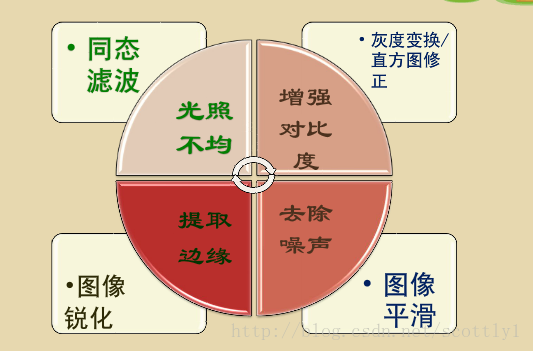
Below is a more intuitive and formulaic explanation. Author: Wind Blows Summer
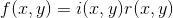
For an image f(x,y) can be multiplied by the irradiation component i(x,y) and the reflection component r(x,y), i.e.
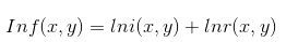
The upper formula can not be directly used to operate the frequency components of contrast and reflection, so the upper formula is logarithmic.
Fourier transform is used on both sides of the upper expression.
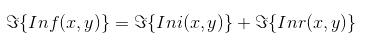
The illumination component of an image is usually represented by slow spatial variations, while the reflection component often causes sudden changes, especially in the connecting parts of different objects. These characteristics lead to the correlation between the low-frequency components of the logarithmic Fourier transform and the irradiation, while the high-frequency components are related to the reflection.
Homomorphic filters can better control the irradiation and reflection components. This controller needs to specify a filter function H(u,v), which can affect the low and high frequencies of Fourier transform by different controllable methods. If gamma L and gamma H are selected and gamma L < 1 and gamma H > 1, the filter function tends to attenuate the contribution of low frequency (irradiation) and enhance the contribution of high frequency reflection. The final result is to compress the dynamic range and enhance the contrast at the same time.


The purpose of homomorphic filtering is to eliminate the influence of uneven illumination without losing image details. The basis is that the gray level of the image is composed of the irradiation component and the reflection component. The reflection component reflects the image content and changes rapidly in space with different image details. The radiation component usually changes slowly in space. The spectrum of the irradiation component falls in the low-frequency region of space, and the spectrum of the reflection component falls in the high-frequency region of space.
Reference 1:
function I3 = homofilter(I) %Homomorphic filtering function
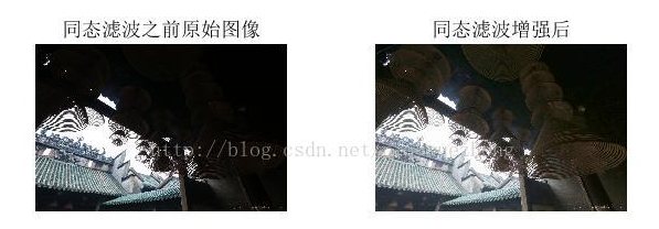
subplot(1,2,1),imshow(I);title('Original image before homomorphic filtering');
I=double(rgb2gray(I));
[M,N]=size(I);
rL=0.5;
rH=5;%The parameters can be adjusted according to the effect required.
c=3;
d0=9;
I1=log(I+1);%Logarithm
FI=fft2(I1);%Fourier transform
n1=floor(M/2);
n2=floor(N/2);
for i=1:M
for j=1:N
D(i,j)=((i-n1).^2+(j-n2).^2);
H(i,j)=(rH-rL).*(exp(c*(-D(i,j)./(d0^2))))+rL;%Gauss Homomorphic Filtering
end
end
I2=ifft2(H.*FI);%Inverse Fourier Transform
I3=real(exp(I2));
subplot(1,2,2),imshow(I3,[]);title('Enhanced homomorphic filtering');
Test functions and results:
%% Same station filter test function
clc,close all,clear all;
img=imread('../image/1.jpg');
I3 = homofilter(img);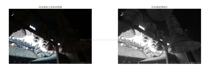
The above program is to gray RGB image and then homomorphic filtering. No direct homomorphic filtering for color image is found on the Internet. So I wrote a program for color image on the basis of the above program:
function I3 = homofilterColor(I)
subplot(1,2,1),imshow(I);title('Original image before homomorphic filtering');
% I=double(rgb2gray(I));
I=double(I);
[M,N,channals]=size(I);
rL=0.5;
rH=5;%The parameters can be adjusted according to the effect required.
c=3;
d0=9;
I3=I;
for ch=1:channals
I1=log(I(:,:,ch)+1);%Logarithm
FI=fft2(I1);%Fourier transform
n1=floor(M/2);
n2=floor(N/2);
for i=1:M
    for j=1:N
        D(i,j)=((i-n1).^2+(j-n2).^2);
        H(i,j)=(rH-rL).*(exp(c*(-D(i,j)./(d0^2))))+rL;%Gauss Homomorphic Filtering
    end
end
I2=ifft2(H.*FI);%Inverse Fourier Transform
I3(:,:,ch)=real(exp(I2));
end

minV=min(min(min(I3)));
maxV=max(max(max(I3)));
for ch=1:channals
for i=1:M
        for j=1:N
            I3(i,j,ch)=255* (I3(i,j,ch)-minV)./(maxV-minV);
        end
end
end

subplot(1,2,2),imshow(uint8(I3));title('Enhanced homomorphic filtering');
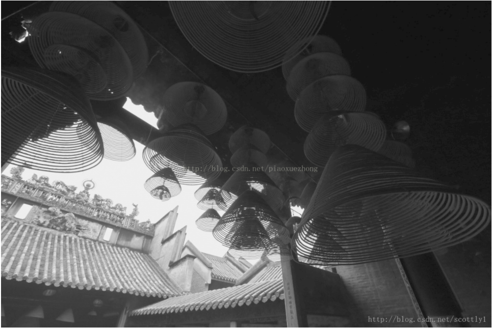
Following is my implementation program in opencv with reference to matlab program, aiming at gray image:
#include <opencv2\opencv.hpp>
#include <iostream>
#include <math.h>

using namespace cv;
using namespace std;
//Homomorphic filtering
void my_HomoFilter(Mat srcImg, Mat &dst)
{
	srcImg.convertTo(srcImg, CV_64FC1);
	dst.convertTo(dst, CV_64FC1);
	//The first step is to take logarithms.
	for (int i = 0; i < srcImg.rows; i++)
	{
		double* srcdata = srcImg.ptr<double>(i);
		double* logdata = srcImg.ptr<double>(i);
		for (int j = 0; j < srcImg.cols; j++)
		{
			logdata[j] = log(srcdata[j] + 1);
		}
	}
	//Second step, Fourier transform
	Mat mat_dct = Mat::zeros(srcImg.rows, srcImg.cols, CV_64FC1);
	dct(srcImg, mat_dct);
	namedWindow("dct", CV_WINDOW_FREERATIO);
	imshow("dct", mat_dct);
	//Third step, frequency domain filtering
	Mat H_u_v;
	int n1 = floor(srcImg.rows / 2);
	int n2 = floor(srcImg.cols / 2);
	double gammaH = 5;
	double gammaL = 0.5;
	double C = 3;
	double d0 = 9.0;
	double d2 = 0;
	H_u_v = Mat::zeros(srcImg.rows, srcImg.cols, CV_64FC1);

	double totalWeight = 0.0;
	for (int i = 0; i < srcImg.rows; i++)
	{
		double * dataH_u_v = H_u_v.ptr<double>(i);
		for (int j = 0; j < srcImg.cols; j++)
		{
			d2 = pow(i-n1, 2.0) + pow(j-n2, 2.0);
			dataH_u_v[j] = (gammaH - gammaL)*exp(C*(-d2 / (d0*d0))) + gammaL;
		}
	}
	H_u_v.ptr<double>(0)[0] = 1.5;
	mat_dct = mat_dct.mul(H_u_v);
	//Fourth step, inverse Fourier transform
	idct(mat_dct, dst);

	//Fifth step, take exponential operation
	for (int i = 0; i < srcImg.rows; i++)
	{
		double* srcdata = dst.ptr<double>(i);
		double* dstdata = dst.ptr<double>(i);
		for (int j = 0; j < srcImg.cols; j++)
		{
			dstdata[j] = exp(srcdata[j]);
		}
	}
	dst.convertTo(dst, CV_8UC1);
}

void main()
{
	Mat src = imread("D:\\fcq_proMatlab\\vessel_edge_extration\\image\\homofilter.jpg",0);
	namedWindow("src:", CV_WINDOW_FREERATIO);
	imshow("src:", src);
	Mat dst(src.rows, src.cols, src.type());
	my_HomoFilter(src, dst);
	namedWindow("dst:", CV_WINDOW_FREERATIO);
	imshow("dst:", dst);
	waitKey();
	system("pause");
}
The results are as follows:
Reference resources:
http://blog.csdn.net/scottly1/article/details/42705271
http://blog.csdn.net/lilingyu520/article/details/46654265
http://blog.csdn.net/bluecol/article/details/45788803
--------
Copyright Statement: This article is the original article of CSDN blogger Naruto_Q. It follows CC 4.0 BY-SA Copyright Agreement. Please attach the link of origin and this statement for reproducing.
Links to the original text: https://blog.csdn.net/piaoxuezhong/article/details/78212814