Introduction: The intelligent vehicle system designed in this paper takes NXP RT1064 microcontroller as the core control unit, and detects the track information through the camera in front of the vehicle body; The real-time speed of the model vehicle is detected by the gear encoder, the speed of the left and right motors is adjusted by the PID control algorithm, and the steering of the steering gear is controlled by the PD algorithm, so as to realize the closed-loop control of the vehicle speed and direction. In order to improve the speed and stability of the model car, a large number of hardware and software tests are carried out by using Matlab, MFC host computer, SD card module, key module, dial switch module and other debugging tools. The experimental results show that the design scheme of the system is feasible.
Team name: cat ear Mahua
Contestants: Shu Hao
Wang Pinlin
Ma Jiaqi
Team leader: Huang Shenzhi
Chen Wanmi
introduction
the National College Students' smart car competition is a science and technology competition that encourages innovation with the guiding ideology of "based on training, focusing on participation, encouraging exploration and pursuing excellence". The competition requires that on the specified vehicle model platform, STC, Infineon and NXP Series MCU are used as the core control module, and a model vehicle that can independently identify the road is produced by adding road sensors, motor drive modules and writing corresponding control programs. The goal of the team members is that the model car needs to complete a series of tasks such as ex warehouse, two laps and warehousing in the shortest time according to the rules.
since the emergence of the magnetic conductivity group in the fifth session to the 16th session of this year, the electromagnetic car has been running on the track of smart cars for eight years. Since the sixth session, the restriction on the forward-looking length has been cancelled, and the speed of the electromagnetic car has begun to make A qualitative leap. The seventh session has been changed to walking upright, which makes the contestants yearn for it with its unique charm and new technical challenges; The eighth session changed back to the four-wheel travel mode and adopted model A, and the speed of the trolley increased significantly again; By the 10th, it was also four-wheel driving and adopted model B for double car chase; By the 11th, it was changed to walking upright again; The 12th session adopted the way of double car chase of B car, and added the element of overtaking, so as to improve the appreciation and technology of electromagnetic car. Up to the 16th competition, AI intelligent group has been born, and the camera has no high limit. OpenArt mini is reflected as the basic unit of AI recognition, and new elements such as AI recognition task and trigeminal are introduced, which greatly increases the interest of the competition and has full attractions.
in this report, our team elaborated our ideas and creativity in detail through the introduction of the overall idea, circuit, algorithm, debugging and vehicle parameters of the car design and production, which is specifically reflected in the innovative design of the circuit and the unique ideas of the algorithm, and the debugging of specific parameters such as single chip microcomputer PID and fuzzy control also made us pay hard work. This report embodies our hard work and wisdom and is the result of our joint efforts.
in the process of preparing for the competition, our team members involved in many disciplines, such as control, pattern recognition, sensing technology, automotive electronics, electrical, computer, machinery and so on. The experience over the past few months has cultivated our abilities in circuit design, software programming, system debugging and other aspects, exercised our ability of knowledge integration and hands-on practice, and most importantly, exercised our aspirations. Under the impact of the epidemic, the conditions for preparing for the competition are scarce. In the face of difficulties, we unite and do not shrink back, and solve problems in the face of problems, which are of great practical significance to our future study, life and work.
Chapter I overall system design
this chapter mainly briefly introduces the overall design idea of intelligent vehicle system. In the following chapters, the whole system is divided into three parts: mechanical structure, control module and control algorithm.
1.1 design of overall system scheme
according to the relevant provisions of the competition rules, the basic four-wheel intelligent vehicle system can adopt any model in the designated vehicle model of the competition, and it is allowed to use various electromagnetic, infrared photoelectric, camera, laser and ultrasonic sensor devices for track and environment detection. The vehicle model microcontroller uses STC, Infineon and NXP Series MCU for software development in KEIL development environment. Using the binary data from the camera, the useful information is returned through the filtering operation and input to the control core for decision-making. The vehicle speed is detected by the encoder speed measurement module, and the pulse count is carried out by using the input capture function of RT1064 to calculate the speed and distance; The motor speed control adopts PID control, and the motor speed is adjusted through PWM control drive circuit to complete the closed-loop control of intelligent vehicle speed. In addition, a dial switch is added as an input and output device to complete the parameter adjustment in Flash for the angle and orientation control of intelligent vehicle.
1.2 overall system scheme design drawing
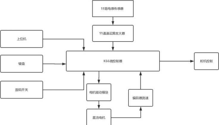
according to the above system scheme design, the racing car includes six modules: RT1064 main control module, sensor module, power supply module, motor drive module, speed detection module and auxiliary debugging module. The functions of each module are as follows:
1. RT1064 main control module: as the "brain" of the whole intelligent vehicle, it will collect the signals of inductive sensors, encoders and other sensors, make control decisions according to the control algorithm, and drive DC motor and servo motor to complete the control of the intelligent vehicle.
2. Sensor module: it is the "eye" of the smart car. It can perceive the track information ahead through certain foresight, so as to provide the necessary basis and sufficient response time for the "brain" of the smart car to make decisions.
3. Power module: provide appropriate and stable power supply for the whole system.
4. Motor drive module: drive DC motor and servo motor to complete acceleration and deceleration control and steering control of intelligent vehicle.
5. Speed detection module: detects and feeds back the speed of the rear wheel of the intelligent vehicle for closed-loop speed control.
6. Auxiliary debugging module: mainly used for function debugging of intelligent vehicle system, racing state monitoring, etc.
Chapter II adjustment and optimization of mechanical structure of intelligent vehicle
the control in intelligent vehicle is realized on the basis of certain mechanical structure. Therefore, before designing the whole software architecture and algorithm, we must have a perceptual understanding of the mechanical structure of the whole vehicle model, and then establish the corresponding mathematical model. So as to adjust the mechanical structure of the car according to the specific design scheme, and continuously improve and improve in the actual debugging process. This chapter will mainly introduce the mechanical structure and adjustment scheme of intelligent vehicle model.
2.1 mechanical modeling of intelligent vehicle body
the racing car model selected in this competition adopts type C model. The mechanical structure of the racing car only uses the chassis part, steering and driving part of the racing model. The control adopts the scheme of front wheel steering and rear wheel drive.
our requirements for mechanical structure are: simple and efficient. After continuous attempts, we have determined the following design schemes:
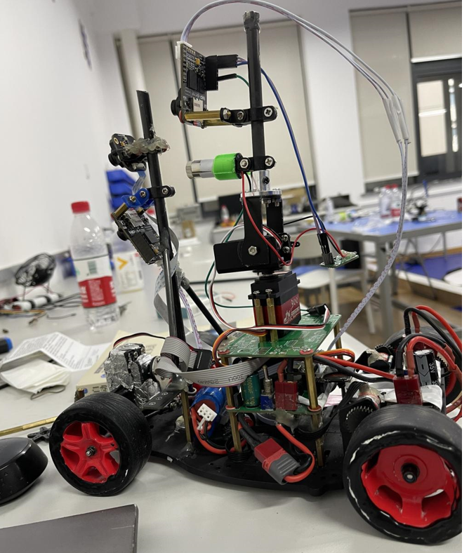
- Wheelbase 203mm
- Front wheel distance 153mm
- Rear wheel distance 155mm
- Total length 380mm
- Total height 310mm
- Total weight 1700g
2.2 adjustment of front wheel positioning of intelligent vehicle
during normal driving of modern vehicles, in order to make the vehicle run stably in a straight line, turn light, automatically return to the right after turning, and reduce the wear of tires and steering system parts, a certain relative installation position must be formed between the steering wheel, knuckle and front axle, which is called wheel positioning. Its main parameters include kingpin tilt back, kingpin tilt in, wheel camber and toe in. The four parameters of smart car competition model car can be adjusted, but there are still some accidents in the general law due to the problem of model car processing and manufacturing accuracy.
2.2. 1 kingpin caster
the so-called kingpin tilt back, It is to tilt the upper end of the kingpin (i.e. steering axis) back slightly. From the side of the car, an included angle is formed between the kingpin axis and the vertical line passing through the center of the front wheel, that is, kingpin caster. The function of kingpin caster is to increase the stability of the car when driving in a straight line and make the front wheel automatically return to the right after steering. Due to the kingpin caster, the kingpin (i.e. steering axis) the intersection point with the ground is located in front of the wheel grounding point. At this time, the action point of the resistance on the wheel is always behind the kingpin axis, which is equivalent to the kingpin dragging the wheel forward. In this way, the stability of the driving direction can be maintained. When the vehicle turns, the resistance action line on the wheel does not pass through the kingpin axis, so the resistance on the wheel is on the kingpin side There is torque acting on the steering wheel to force the wheel to automatically deflect until the resistance action line of the wheel passes through the kingpin axis. At this time, the wheel has been aligned, which is the automatic alignment function of the steering wheel.
the greater the caster angle of the kingpin, the better the directional stability and the stronger the automatic centering effect, but the heavier the steering. The caster angle of the automobile kingpin generally does not exceed 3 °, which is guaranteed by the installation position of the front suspension on the frame. Due to the low-pressure wide radial tire used in modern cars, the tire deformation increases and the grounding point moves backward when driving at high speed. Therefore, the caster angle of the kingpin can be reduced or even negative (becoming the kingpin forward inclination), so as to avoid the front wheel shimmy caused by excessive return torque.
the model car changes the kingpin caster angle by increasing or decreasing the number of yellow shims. Because the steering steering steering gear torque used in the competition is small, too large kingpin caster angle will make the steering heavy and the turning response sluggish, so it is set to 0 ° to increase its steering flexibility.
2.2. 2 kingpin inclination
the so-called kingpin inclination, Yes, the kingpin The upper end of (i.e. steering axis) tilts inward. Viewed from the front of the vehicle, an included angle is formed between the kingpin axis and the vertical line passing through the center of the front wheel, i.e. kingpin inclination. The role of kingpin inclination is to enable the wheels to automatically return to normal in time after steering and make steering light. For model vehicles, the kingpin inclination can be changed by adjusting the length of the screw of the front axle, because it is too large The internal inclination angle of can also increase the steering resistance and tire wear, so it can be approximately adjusted to about 0 ° - 3 ° during adjustment, which should not be too large.
both kingpin inclination and kingpin inclination can make the car turn automatically back to the right and keep driving in a straight line. The difference is that the return of kingpin inclination is independent of the vehicle speed, and the return of kingpin inclination is related to the vehicle speed. Therefore, the return of kingpin inclination is large at high speed and large at low speed.
2.2. 3 camber angle
camber angle refers to the angle between the intersection of the vehicle transverse plane and the wheel plane passing through the wheel center and the vertical line on the ground, which has a direct impact on the vehicle's steering performance. Its function is to improve the steering safety of the front wheel and the portability of steering control. In the transverse plane of the car, when the tire is in the shape of "eight", it is called "negative camber", while when it is in the shape of "V", it is called positive camber. If the wheel is vertical to the ground, it is easy to deform once fully loaded, which may cause the upper part of the wheel to tilt inward, resulting in damage to the wheel coupling. Therefore, the wheel shall be calibrated to a positive camber angle in advance, which is generally about 1 ° to reduce the bearing load, increase the service life of parts and improve the safety performance of the vehicle.
the model car provides special camber adjustment accessories to approximately adjust its camber. Since the model is mainly used for racing in the competition, it is required to reduce the weight as much as possible. The load on the chassis and front axle is small, so the camber angle can be adjusted to 0 ° and should match the front wheel toe in.
2.2. 4 front wheel toe in
toe in refers to the difference between the rear distance and the front distance between the two wheels, and also refers to the included angle between the front wheel centerline and the longitudinal centerline. The function of front wheel toe in is to ensure the driving performance of the vehicle and reduce tire wear. When the front wheel rolls, its inertia force naturally deflects the tire inward. If the toe in is appropriate, the deflection direction of the tire during rolling will be offset, and the wear on the inner and outer sides of the tire will be reduced. Like the inner splay, the one with small front end and large rear end is called "toe in", otherwise it is called "toe in" or "negative toe in". In the actual automobile, the toe in is generally 0-2mm.
in the model car, the toe in of the front wheel is realized by adjusting the left and right tie rods driven by the servo motor. After the position of the kingpin in the vertical direction is determined, the toe in of the front wheel can be changed by changing the length of the left and right tie rods. In the actual adjustment process, we found that a smaller toe in and a constraint of 0-2mm can reduce the steering resistance and make the steering of the model car easier, but the actual effect is not very obvious.
although the kingpin caster, kingpin inclination, wheel camber and toe in of the model vehicle can be adjusted, there are still many contingencies in the general law due to the problems of vehicle model processing and manufacturing accuracy, and all are subject to the actual adjustment effect.
2.3 adjustment and optimization of intelligent vehicle steering mechanism
the ideal steering model refers to the vehicle steering modeling when the tire does not slip, ignoring the deformation of the left and right tires due to uneven stress, and ignoring the deformation of the tires under the influence of gravity. Under this ideal model, the turning radius of the car body can be calculated.
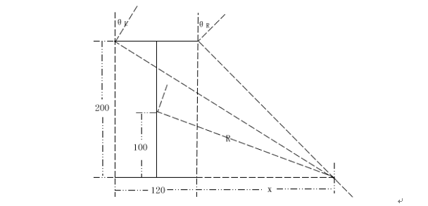
as shown in Figure 2.2, it is assumed that the intelligent vehicle system is an ideal steering model and its center of gravity is located at its geometric center. The wheels meet the steering principle. The axis of the left and right wheels and the axis of the rear wheel must intersect at one point.
steering mechanism plays a very important role in vehicle operation. Proper front axle and steering mechanism can ensure that the vehicle will not deviate during straight-line driving, and can ensure the directional stability of the vehicle; When the vehicle turns, the appropriate steering mechanism can make the vehicle return to the straight-line driving state, which has good righting. It is for these reasons that the optimal design of steering system has become the focus of mechanical structure in intelligent vehicle design, which is directly related to whether the car can successfully complete the race. In practice, we optimize the scheme through theoretical calculation, and then make the actual structure to verify the theoretical data, and constantly improve in the actual debugging process.
in the process of making the model car, the steering of the car is realized by driving the left and right tie rods by the steering gear. The rotation speed and power of the steering gear are certain. The only way to speed up the response speed of the steering mechanism is to optimize the installation position and torque of the steering gear and extend the length of the rod. Because power is a function of the product of speed and torque, excessive pursuit of speed will inevitably lose torque, and too small torque will also cause slow steering. Therefore, the relationship between the response speed of steering mechanism and the torque of steering gear should be comprehensively considered in the design, and an optimal steering effect should be obtained through optimization. After the final actual parameter design and calculation, a set of parameters and mechanism that can work stably and efficiently are obtained.
as shown in Figure 2.3, we finally designed this set of steering links. We comprehensively considered the relationship between speed and torque, simplified the installation mode and achieved the expected goal according to the specific structure of the model vehicle chassis.
2.4 adjustment of rear wheel reduction gear mechanism of intelligent vehicle
the rear wheel of the model car is driven by RS380 motor, and the transmission ratio between the motor shaft and the rear axle is 4.25. The gear transmission mechanism has a great influence on the driving capacity of the vehicle model. The improper installation position of the gear transmission part will greatly increase the load of the motor-driven rear wheel and seriously affect the final result. The adjustment principle is: the two transmission gear shafts shall be kept parallel, and the fit clearance between the gears shall be appropriate. If it is too loose, it is easy to break the gear, and if it is too tight, it will increase the transmission resistance and waste power; The transmission part shall be easy and smooth without hysteresis or periodic vibration. The basis for judging whether the gear transmission is good is to listen to the sound when the motor drives the rear wheel to idle. The sound is harsh and loud, indicating that the fit clearance between gears is too large and there is tooth collision in transmission; If the sound is dull and sluggish, it indicates that the fit clearance between gears is too small, or the two gear shafts are not parallel, and the motor load becomes larger. The adjusted gear transmission noise is very small, and there will be no collision noise. The rear wheel reduction gear mechanism is basically adjusted, and the power transmission is very smooth.
2.5 tire maintenance and use
model C of this competition adopts rubber with tread pattern. The main problems exposed in the process of use are: insufficient tire grip when driving at high speed; The strength of tire material is insufficient, and it is easy to wear after long-term use. In the rules, it is not allowed to change the tire performance. Therefore, we try to choose symmetrical and round tires during commissioning; Change the front wheel inclination angle as much as possible to maximize the comprehensive contact area between the tire and the ground under various working conditions; Try to avoid the contact between the four wheels and the ground during the non commissioning time to ensure that the shape of the tire does not change.
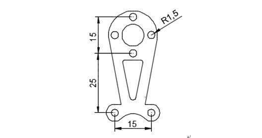
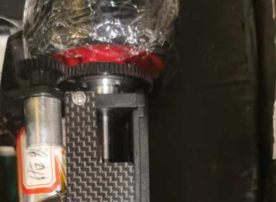
2.6 installation of encoder
in order to improve the accuracy, the vehicle uses an encoder. In order to facilitate installation and reduce weight, we choose to use the hole position of the original model for the installation of the encoder, which better ensures the parallelism of the two meshing gear shafts and the smoothness of transmission.
2.7 adjustment of center of gravity position of intelligent vehicle
in order to achieve a long-term perspective, OpenArt mini needs to be installed as a new identification unit because the camera height is not limited. If the front weight is too concentrated, the center of gravity of the vehicle will be particularly forward, and the positive pressure of the rear wheel is insufficient, resulting in tail flick. In order to move the center of gravity backward, we have tried many ways to build sensor supports to minimize the weight on the premise of ensuring structural stability. At the same time, we moved the steering gear and battery back, appropriately increased the rear counterweight of the body, and achieved the expected effect.
2.8 adjustment of other mechanical structures
in addition, there are many improvements in the mechanical structure of the model car, such as wheels, suspension, chassis, body height, etc.
model car at high speed (2.3m/s-3.5m/s) due to the fast acceleration and deceleration process, the relative displacement between the tire and the rim of the model car is easy to cause relative displacement, which may cause some driving forces to lose when accelerating. In the experiment, it is shown that the relative displacement of a few centimeters between the tire and the hub usually occurs when the car runs at high speed, which seriously affects the acceleration process of the car. In order to solve this problem, we stick the tire on the wheel in the actual debugging process, which can effectively prevent the loss of driving force caused by the dislocation of tire and rim.
in addition, we have also improved and adjusted the body height, as well as the shape and quality of the chassis, and achieved good results.
Chapter 3 hardware system design and implementation
3.1 hardware design of main control board and drive board
from the initial hardware circuit design, we have set the design goal of the system: reliable, efficient and concise, and strictly follow the specifications in the whole system design process.
reliability is the first requirement of system design. We have carried out EMC design for all links of the circuit design, done well in the grounding, shielding and filtering of each part, and laid tin foil outside to separate the high-speed digital circuit from the analog circuit, so that the reliability of the system meets the design requirements.
high efficiency and practicability means that each module of the system can fully and perfectly realize the corresponding functions. The new model C adopts double motor drive. We have designed a separate drive chip to form the driver. The maximum instantaneous drive current can reach tens of amps.
simplicity means that after meeting the requirements of reliability and efficiency, in order to minimize the load of the model car and reduce the center of gravity of the model car, the circuit design should be as concise as possible, reduce the number of components and reduce the area of the circuit board, so that the circuit part is light and easy to install. After designing the schematic diagram, pay attention to the layout of the PCB board and optimize the wiring of the circuit, Arrange the components in order, and finally achieve the simplicity of the circuit board.
3.1. 1 power management module
the power module is extremely important for a control system, which is related to whether the whole system can work normally. Therefore, the appropriate power module should be selected when designing the control system. According to the competition rules, the standard model uniformly distributed by the smart car competition is used for the competition, and the power is supplied by 7.2V 2000mAh Ni Cd or lithium battery (two 18650,2AH, equipped with protective plate). We choose the lithium battery power supply scheme after actual attempt and comparison.
in order to meet the needs, there are four kinds of power supply voltages on this model:
1) the smart car uses lithium batteries (two 18650,2AH, equipped with protection board) for power supply. When fully charged, the voltage is 7.8 ~ 8.4V, which can be directly used for DC motor power supply.
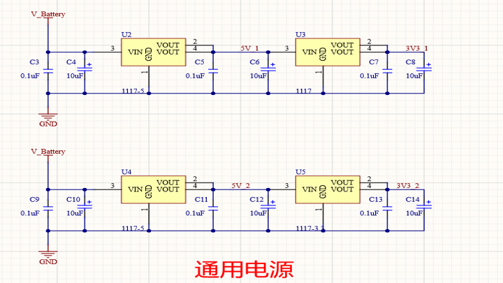
2) some digital devices use DC 5V, and the 5V power supply adopts linear voltage stabilizing chip LM1117-5V.
3) 3.3V is used to supply power for single chip microcomputer system, human-computer interaction module and electromagnetic sensor module, and linear voltage stabilizing chip LM1117-3.3V is used.
generally speaking, the linear power supply samples the output voltage and then sends it to the comparison voltage amplifier with the reference voltage. The output of the voltage amplifier is used as the input of the voltage regulator to control the regulator so that its junction voltage changes with the input, so as to adjust its output voltage. The technology is mature, the production cost is low, and the stability can meet the requirements.
4) the motor drive module uses DC 12V and MC34063 boost power module. Add several LED s to display the working conditions of various power supplies.
the schematic diagram of this part is shown in Figure 3.1.
3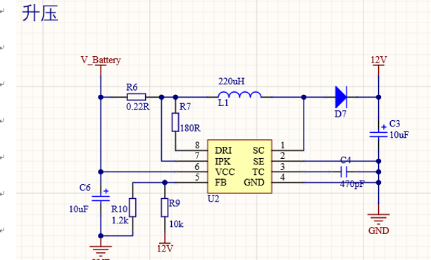
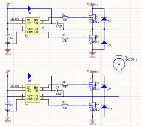
3.1. 2 motor drive module
the motor drive circuit is a reversible bipolar bridge driver of DC motor made of discrete components. Its power component is composed of four N-channel power MOSFET tubes. The rated working current can easily reach more than 100A, which greatly improves the working torque and speed of the motor. The driver is mainly composed of the following parts: PWM signal input interface, logic commutation circuit, dead band control circuit, power supply circuit, upper bridge arm power MOSFET grid driving voltage pumping circuit, power MOSFET grid driving circuit, bridge power driving circuit, buffer protection circuit, etc; The special gate drive chip usually has the functions of preventing the same arm conduction, hardware dead band, undervoltage protection and so on, which can improve the reliability of the circuit.
there are two common motor driving modes:
1, Integrated motor drive chip;
2, It is designed with N-channel MOSFET and special gate driver chip.
among the common integrated H-bridge motor drive chips on the market, 33886 chip has excellent performance. The chip has perfect overcurrent, undervoltage, over temperature protection and other functions. The internal MOSFET on resistance is 120 milliohm and has a maximum 5A continuous working current. The circuit using integrated chip has simple design and high reliability, but its performance is limited. Because the internal resistance of the competition motor is only a few milliohms, and the on resistance of each MOSFET in the integrated chip is more than 120 milliohms, which greatly increases the total resistance of the armature circuit. At this time, the speed drop of the DC motor is large, the efficiency of the driving circuit is low, and the motor performance can not be brought into full play.
because the discrete N-channel MOSFET has very low on resistance, the total resistance of armature circuit is greatly reduced. In addition, the specially designed gate drive circuit can improve the switching speed of MOSFET, improve the modulation frequency of PWM control mode, and reduce the armature current pulsation. And the special gate drive chip usually has the functions of preventing the same arm conduction, hardware dead zone, undervoltage protection and so on, which can improve the reliability of the circuit.
1. Selection of special gate drive chip:
IR company is known as the leader of power semiconductors, so we mainly choose from IR company's products. Among them, IR2104 half bridge driver chip can drive two N-channel MOSFET s at the high end and low end, provide large gate driving current, and have the functions of hardware dead band, hardware anti same arm conduction and so on. Two IR2184 half bridge drive chips can be used to form a complete DC motor H-bridge drive circuit. Because of its perfect function, low price and easy purchase, we choose it for design.
2. Selection of MOSFET:
the main factors considered when selecting MOSFET are: withstand voltage, on internal resistance and packaging. The smart car power supply is a battery pack with a rated voltage of 7.2V. Since the motor may be in the state of regenerative power generation during operation, the withstand voltage value of the components of the driving part should preferably be more than twice the power supply voltage, that is, the withstand voltage is more than 16V. The smaller the on internal resistance, the better. The larger the package, the greater the power, that is, the greater the passing current under the same on resistance, but the larger the package, the greater the gate charge, which will affect the on speed. Commonly used MOSFET packages include TO-220, TO-252, SO-8, etc. TO-252 package has large power and small gate charge. So we finally chose LR7843 N-channel MOSFET packaged by IR company TO-252, VDSS=55 V, RDS(on)=8.0 milliohm, ID=110 a.
3. Principle analysis of driving circuit and determination of component parameters
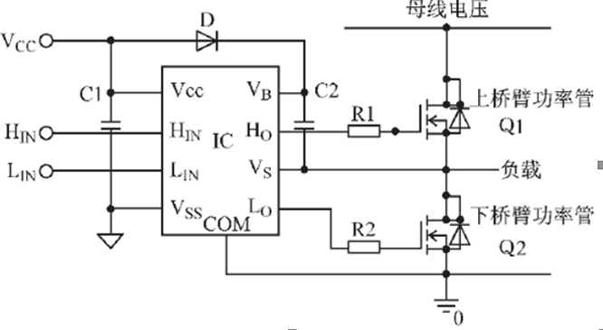
this drive design is easy to understand only from the signal logic analysis, but to deeply understand and better apply, it is necessary to make a more in-depth analysis of the circuit and make theoretical analysis and calculation on the parameter determination of some peripheral components. The IC in Figure 3.8 is a high-voltage driver chip that drives two half bridge MOSFET s. Vb and Vs supply power to the high-voltage terminal; Ho is the drive output of high voltage end; COM is the driving power supply of low-voltage end, and Lo is the driving output of low-voltage end; Vss supplies power to digital circuits The upper and lower bridge arms of this half bridge circuit are connected alternately. Whenever the lower bridge arm is turned on and the upper bridge arm is turned off, the potential of Vs pin is the saturated on voltage drop of lower bridge arm power tube Q2, which is basically close to the ground potential. At this time, Vcc charges the bootstrap capacitor C2 through bootstrap diode D to make it close to Vcc voltage When Q2 is turned off, the voltage at Vs terminal will rise. Since the voltage at both ends of the capacitor cannot change suddenly, the level at Vb terminal is close to the sum of the voltages at Vs and Vcc terminals, while the voltage between Vb and Vs is still close to Vcc voltage When Q2 is turned on, C2 drives Q2 as a floating voltage source; The charge lost during the opening of C2 in Q2 will be supplemented in the next cycle. This bootstrap power supply method is realized by constantly swinging the level of Vs terminal between high and low levels. Since the bootstrap circuit does not need floating power supply, it is the cheapest. As shown in the figure, the bootstrap circuit charges a capacitor, and the voltage on the capacitor fluctuates up and down based on the source voltage of the high-end output transistor. D and C2 in Figure 2.6 are the pulse width modulation of IR2104 (PWM) components shall be strictly selected and designed during application, and calculated and analyzed according to certain rules; and adjusted during circuit experiment to make the circuit work in the best state. Among them, D is an important bootstrap device, which shall be able to block the high voltage on the DC main line, and its current is the product of grid charge and switching frequency. In order to reduce charge loss, the device with small reverse leakage current shall be selected Fast recovery diode, the power supply of the high-voltage part in the chip comes from the charge on the bootstrap capacitor C2 in the figure; In order to ensure that the high voltage part of the circuit has sufficient energy supply, the size of C2 shall be properly selected
MOSFET has similar gate characteristics. When turned on, it needs to provide sufficient gate charge to the gate in a very short time. On the charging path of bootstrap capacitor, the distributed inductance affects the charging rate, The narrowest conduction time of the lower bridge arm power tube shall ensure that the bootstrap capacitor has enough charge to meet the charge required by the grid, plus the charge lost by the leakage current when the power device is turned on stably Therefore, considering that the narrowest conduction time is the minimum value, the bootstrap capacitance should be small enough; To sum up, it should be considered when selecting the bootstrap capacitor, which can not greatly affect the driving performance of narrow pulse; It should not be too small to affect the driving requirements of wide pulse. It should be selected and estimated from the working frequency, switching speed and gate characteristics of power devices.
the schematic diagram of this part is shown in Figure 3.2.
3.2 intelligent vehicle sensor module design
the system uses RT1064 chip as the controller and the global shutter digital camera MT9V032 as the information acquisition sensor. The original collected image is a two-dimensional matrix converted by analog circuit, which is a gray image.
Chapter IV software system design and implementation
the control program is the embodiment of human thought in the car model. The program should be systematic, modular and stable. The goal is to maximize the hardware circuit and mechanical performance, so that the car model can complete the race at the fastest speed.
4.1 bottom initialization
write the initialization function init (), and the modules used for initialization are as follows (the sub functions are omitted):
void init(void)
{
 gpio_init(D12,GPO,0,GPIO_PIN_CONFIG);//Buzzer
 Boma_init();
oled_init();
ips114_init();
 encoder_init();
 mt9v03x_csi_init();
 motor_init();
 servo_init();
 pit_initiate();
 flash_init();
 buton_init();
 AI_uart_init();
 AI_uart_init1();
 seekfree_wireless_init();
 icm20602_init_spi();
}
4.2 sensor acquisition and processing algorithm
due to the uneven light of the track, there are many invalid information of the distant track, and the reflection of the track is uncontrollable. The judgment of special track elements has great interference. In order to make the system more stable, improve the robustness and portability of the system, and provide as much track information as possible, these factors must be shielded in the software system design.
gray image information is complex and difficult to process. The system uses image filtering, edge detection, image correction, binarization and other algorithms to optimize the image. Then it is easy to judge various special elements.
4.2. 1 image filtering
the gray image has many jump points and the image is more complex. In order to better identify the track type, first filter the track image.
statistically sort and filter the images. The 3 * 3 filter is used for linear spatial filtering of the image, the filter template is multiplied by the corresponding gray value in the image, and the average gray value in the center of the template is obtained.
g(x*y)=∑_(s=-a)^a▒ ∑_(t=-b)^a▒〖w(s,t)f(x+s,y+t)〗
a=(m-1)/2,b=(n - 1)/2
filtering process:
g(x,y)=(∑_(s=-a)^a▒ ∑_(t=-b)^b▒〖w(s,t)f(x+s,y+t)〗)/(3*3)
median filtering method is a nonlinear smoothing technology, which sets the gray value of each pixel as the median of the gray values of all pixels in a neighborhood window of the point. Median filter is very effective in dealing with salt and pepper noise. Pave the way for later image processing.
4.2. 2 image sharpening
in the gray image, the track edge is blurred. In this system, the first-order differential is used to sharpen the image. 3 * 3 sharpening template is as follows.
Z=[■(z1&z2&z3@z4&z5&z6@z7&z8&z9)]
g_x=∂f/∂x=(z_7+2z_8+z_9 )-(z_1+2z_2+z_3 )
g_y=∂f/∂y=(z_7+2z_8+z_9 )-(z_1+2z_2+z_3 )
M(x,y)=|(z_7+2z_8+z_9 )-(z_1+2z_2+z_3 )|+|(z_7+2z_8+z_9 )-(z_1+2z_2+z_3 )|
Soble operator is as follows:
S1=[■(-1&-2&-1@0&0&0@1&2&1)]
S2=[■(-1& 0& 1@-2& 0& 2@-1& 0& 1)]
Sobel operator can sharpen edge information.
4.2. 3 image correction
in order to obtain more information, a 140 degree camera is used in the intelligent vehicle system. However, barrel distortion will occur on the track. Barrel distortion is a distortion phenomenon that the imaging picture is barrel expansion caused by the lens. The shape of the track is deformed, which is not conducive to the judgment of track elements.
in order to restore the original image to the original state as much as possible, we carry out inverse perspective transformation and use matrix transformation to realize the mapping from camera image to real image.
4.2. 4 image scanning
the core part of the camera algorithm is the extraction of the left and right sidelines, so as to calculate the position of the center line and the track deviation and guide the driving direction of the car. Sideline extraction and centerline calculation:
1. The near image is more reliable than the far image, so the edge line is extracted from near to far;
2. In the last line, search the edge from the middle to both sides to find the edge to ensure the effectiveness of the nearby image;
3. The next line adopts edge tracking, and dynamically determines the search range of the black line of the line according to the black line position of the previous line, so as to search the black line and save time;
4. If the left and right lines of several consecutive lines cannot be found, it is judged as a cross bend, extend the left and right lines, and then find the effective edge line;
5. If both the left and right edges are found, the center line of the line is directly weighted by the equal weight of the left and right edges; If one side line is lost, the center line shall be calculated according to the track width of the previous effective line and the position of the other side line;
6. After calculating the center line, the center line can be modified to be more in line with the reality.
4.3 judgment of special elements
there are many special elements in the smart car track. Such as roundabout, ramp, garage and other elements. These elements require the software system to actively identify and specifically control vehicle motion.
4.3. 1 roundabout treatment
our processing idea is divided into ring in recognition, ring in recognition and ring out recognition. For ring in recognition, one side of the image boundary is a straight line, the other side is blank, curve, blank, and the straight line can be judged as a ring island. Then the midline array is processed to make the trolley corner into the roundabout. For in ring identification, as long as the curve curvature on one side is relatively large. Out of loop identification: if one side is a long straight line, it can be judged as out of loop.
4.3. 2 garage treatment
garage elements are located in departure and parking areas, which requires us to improve the accuracy of intelligent vehicle recognition algorithm. Speed control is sensitive and reliable.
in the garage element, we first judge the arrival of the garage ahead. After the judgment is successful, reduce the speed to achieve stable warehousing. After entering the garage, reduce the speed to zero.
4.4 AI treatment
4.4. 1 Camera Settings
the camera is OpenArt mini. The first version of the scheme is that a single camera can complete the track task. Limited by the total drilling wind height, it can complete all tasks by standing above the total drilling wind. The second version is a dual camera scheme. One front and one rear, the former completes the digital and tag recognition, and the latter completes the fruit and target shooting tasks.
because the frame rate of openartmini is not high, it is easy to miss detection. The core factor is that the frame rate of openartmini can not keep up with the running speed of the trolley, The combination of RGB565 and QVGA is selected in color (RGB565, GRAYSCALE) and resolution (QQVGA, QVGA). Although the gray image with QQVGA resolution is the least for the image data to be processed (the highest frame rate), it is not friendly to the recognition task due to its low resolution, so it is abandoned after trying.
due to the slow processing of large-scale image data, the corresponding element recognition is selected after receiving MCU data.
4.4.2 AprilTag recognition principle
AprilTag is a visual reference library, which is widely used in the fields of AR, robot and camera calibration. Through a specific flag (similar to QR code, but reducing the complexity to meet the real-time requirements), the flag can be detected quickly and the relative position can be calculated.
the content of AprilTag mainly includes three steps:
the first step is how to detect various edges in the image according to the gradient.
the second step is how to find the required quadrilateral pattern in the edge image and filter it. AprilTag detects the detected edge as much as possible. First, eliminate the non-linear edge, and find the adjacent edge on the linear edge. Finally, if a closed loop is formed, a quadrilateral is detected.
the last step is how to encode and decode two-dimensional codes. There are three coding methods. The black edge color block lengths are 8, 7 and 6 respectively. For the decoded content, a point array should be generated in the detected quadrilateral to calculate the value of each color block, Then, a simple classifier is constructed according to the local binary patterns to classify the color blocks in the quadrilateral, encode the positive color block as 1 and the negative color block as 0, and the coding of the two-dimensional code can be obtained. After obtaining the code, match it with the code in the known library to determine whether the decoded QR code is correct.
since the Apriltag code can be directly used in openartmini, the Apriltag code can obtain high accuracy only through a simple image processing.
4.4. 3 image processing
Apriltag code is most prone to two problems in the recognition process: missed detection and false detection.
for the problem of false detection, some unknown images will be seen during the movement of the trolley, and they will be recognized as Apriltag code. At the beginning, the filtering solution is selected, and the same tag is recognized twice in a row_ ID, it is recognized as the tag code. The accuracy of this method is 100%, but it is easy to cause the problem of missed detection, that is, when the vehicle passes the tag code, only the tag code in one frame of image is detected. Then select the roi area and effective tag for setting mini_ The range of ID can effectively improve the camera frame rate and prevent the recognition of clutter as tag to a certain extent, which is close to 100%.
for the missing detection problem, the core factor is that the openartmini frame rate can not keep up with the speed of the car. Therefore, the roi area is set to reduce the amount of data processing. The size of the roi area can be changed according to the position of the tag code in the track, so as to achieve the optimal scheme. Gray image with QQVGA resolution will be faster in identifying tag, but the improvement effect is not obvious.
the number recognition method is to find the rectangle in the specified area first, and then complete the target recognition through the ten classification model.
the identification box calls find in openmv_ Rect function, because this function identifies rectangles through the quaternion detection algorithm, if the boundary size is too small, it is easy to identify interference factors such as the track as rectangles, and if the boundary size is too large, it is sometimes difficult to identify the specified target, Therefore, through a more appropriate threshold (50000) and rectangular features (length, width and position), the required rectangle is selected, such as the length width ratio of the rectangle or the separate length and width (taking into account the graphic distortion, in fact, it can be determined according to the stop position).
lenet-5 model is selected for the model, which is quantified by nncu tool, and the quantization digit is 9, The data set is photographed by itself, with 500 numbers per piece, and the accuracy is about 95%.
4.4. 4 fruit animal model
fruit animal identification reference number identification. When training fruit animal data sets, there are two schemes: one is to train the two classification model, the other is to train the ten classification model. Our model is trained through the cifar-10 model, and then the recognition results are divided into two categories. In a small test set, regardless of the advantages and disadvantages, but analyzed from the characteristics, The features that can be extracted from each category of animals are greater than the common features that can be extracted from a large category of animals, that is, the second classification after the tenth classification is more accurate.
4.4. 5 fruit shooting
after identifying the fruit, we have to carry out target shooting. We have tried two schemes.
due to certain errors in the construction of mechanical structure, there can be no errors between the laser and the central axis of the camera, so it is necessary to adjust the zero through the program, that is, the external parameters of the camera. If it is necessary to adjust the internal and external parameters in one step through forward and inverse kinematics transformation after camera calibration, the adjustment of internal and external parameters is an unavoidable step, and other methods only need to correct the camera deviation.
scheme 1: set the laser height to 15cm according to the rules, and make the laser hit the bull's-eye through the movement of the trolley. When no fruit is recognized, a forward command is issued. When the fruit is identified, judge the deviation pan_error, when pan_ When error is less than 0, a forward command is issued when pan_ When error is greater than 0, a backward instruction is issued. There are two points to note: since the camera is controlled by the steering gear, the left and right pan_ The forward or backward command of error is just the opposite, that is, when the deviation is less than 0, it is the front. In addition, a memory unit is still needed to record the instruction of the previous step to prevent jitter (when a frame of image is not recognized as a rectangle during backward, a forward instruction is issued).
scheme 2: PID adjusts the steering gear, and calculates the next required duty cycle through PID through the deviation from the center point. This kind of method is relatively simple, but openartmini should not be used to control the steering gear. Because the 0-255 duty cycle can not meet the high-precision rotation, the error will be large, so MCU control should be selected. In addition, when the distance is far, the problem caused by the perspective transformation of the image will be encountered. The midpoint of the rectangular box is not the center of the picture, so the deviation is not credible. The solution can only calculate the position of the actual center point through the camera internal parameters obtained by camera calibration, but it is not necessary.
therefore, the best scheme should be the combination of scheme 1 and scheme 2. Rotate the steering gear within an appropriate deviation range for PID adjustment.
4.4. 6 animal parking
the operation after identifying the animal is completed by the master control, which is not repeated.
4.5 speed control and turning strategy
4.5. 1 direction control based on position PID
PID control is the most widely used regulator control method in engineering practice. Since it came out more than 70 years ago, it has become one of the main technologies of industrial control because of its simple structure, good stability, reliable operation and convenient adjustment.
[general principles, 3000 words omitted here...]4.5. 3 curve analysis
when the vehicle enters the corner, three parameters need to be set: cutting path, steering angle and entering speed.
among them, the turning path mainly determines whether the vehicle chooses to turn on the inner road or the outer road. The Cheney road has the shortest path, but if the ground adhesion coefficient is too small, it will lead to the unstable driving state of side slip. The reason is that the radius of curvature is too small and the speed is very fast, so the centripetal force required by the model car will be very large. The track itself is a plane structure, and the centripetal force will be provided by the friction force from the ground, Therefore, the adhesion coefficient of the track surface will have a great impact on the running state of the car. When cutting the outer lane, the path will be slightly longer, but there are more adjustment opportunities. At the same time, the increase of curvature radius will make the model car have higher turning speed.
the steering angle determines the stability of the vehicle when cornering. The appropriate steering angle will reduce the adjustment of the vehicle when turning, which can not only ensure the optimal path, but also improve the efficiency and reduce the time. When considering the setting of steering angle, we should pay attention to the following problems: for the sensor detecting track offset, the steering sensitivity with small increment; Steering sensitivity when a large curve is detected; For the treatment of changing direction continuous curve similar to S-bend.
for the analysis of bending speed, the influence of path and steering angle should be comprehensively considered. In short, we will adopt the scheme of slowing down in the turn and accelerating out of the turn, which can theoretically reduce the time spent in turning. However, in the past few races, after observing the treatment of curves by participating cars, we found that not everyone chose the same scheme. As mentioned earlier, simply analyzing the turning speed without connecting the path and steering angle will lead to limitations or even errors in thinking. For example, if we adopt the scheme of "slowing down and accelerating out of the corner" when we can't judge the sign points of entering and exiting the corner in time, the driving state in the corner will be unstable and the path will be poor. At the same time, the timing of accelerating out of the corner is too late, which will also waste time. Therefore, referring to some experience of actual driving, the system determines the processing method of turning speed as follows: decelerate sharply when entering the corner, so as to obtain sufficient adjustment time and obtain the correct steering angle; Increase the speed properly in the curve and keep the angle unchanged, so as to save time for acceleration when turning out; When turning, judge the sign accurately first, and then accelerate. Although it will take some time, facing the continuous turning curve, it can reduce the probability of judgment error and ensure the stability of driving state. Moreover, the limited acceleration in the curve is also very helpful for the subsequent acceleration. It is worth considering that the driving stability can be replaced with the acceptable additional time.
the advantages and disadvantages of each scheme are explained below in several common corner processing methods, in which the abscissa represents the offset of the track center line collected by the sensor from the car center line, and the ordinate represents the corner size.
a diagram shows that the offset has a linear relationship with the steering angle. It is relatively simple in calculation and programming, and can also achieve the goal of controlling the driving of the car. However, due to the simple formulation of rules and the incomplete analysis of the actual driving state of the car, it can not be simply applied in practical application.
b figure shows that when the car deviates slightly from the center of the track, do not make too much adjustment to the driving direction, but quickly adjust the angle when the deviation is large to the predetermined value to ensure the timely turning. At the same time, do not make large changes after judging that it is a sharp turn, because the value of the angle is already large at this time, Just fine tune the steering gear to ensure the correctness of the direction. The advantage of this scheme is that it comprehensively considers the adaptability of the car to a curve and ensures the stability and anti-interference when driving in a straight line, but the response to sharp turns may not be timely, which is the main disadvantage of this scheme.
the processing scheme for curves shown in figure c is just opposite to figure B. it improves the corresponding sensitivity and reduces the anti-interference. It has good adaptability to the track with multiple curves and small curve radius.
d and e are two special processing schemes. They can not be used for the whole process control of the car, but they have special requirements for the offset of a certain part in view of the actual operation characteristics of the car. For traditional four-wheel vehicles, there is a strict angle relationship between the front wheels when steering, and their results are determined by the steering system. In this way, both systems limit a certain value, which will inevitably lead to contradictions. When the car changes from 0 degrees to the maximum angle, it can not meet the limitations of the two conditions at the same time at all times. Then, for the driving stability of the car, we may wave the angle in a small range to obtain the most appropriate angle value nearby and reduce the contradiction.
4.5. 4 curve analysis and strategy formulation
in the smart car competition, we use segmented PID and segmented speed for control, that is, we change the Kp, Kd and speed of the car according to the size of the differ ence. In the actual situation, the effect is remarkable. The specific parameter adjustment process is shown below.
Chapter V description of development tools, production, installation and commissioning process
5.1 development tools
the development of the program is carried out under KEIL, including the writing, compiling and linking of the source program, and finally generating the executable file.
5.2 commissioning process
5.2. 1 parameter setting of control algorithm
the key to using PID control is to adjust three proportional coefficients, namely parameter setting. There are two kinds of PID tuning methods: one is theoretical calculation tuning method. It mainly determines the controller parameters through theoretical calculation according to the mathematical model of the system. Because the whole system of intelligent vehicle is a distributed parameter system with high electromechanical coupling, and the specific environment of the track should be considered, it is difficult to establish an accurate mathematical model of intelligent vehicle motion control, and the mechanical structure of the vehicle body is often modified, the model parameters change frequently and the operability is not strong; The second is the engineering setting method, which mainly depends on engineering experience and is directly carried out in the test of control system, and the method is simple. This method is adopted.
1. Parameter setting of direction control algorithm
position PID control is adopted for direction control. As the car tracking is essentially a follow-up system, the accumulated deviation of the integral term in the curve is wrongly added to the tracking of the straight road, resulting in inaccurate steering when entering the straight road. Although tracking can be realized when running the straight road, the steering adjustment is often overshoot, resulting in left-right vibration of the car body on the straight road, which seriously affects the overall performance of the car.
set the integral term coefficient Ki to 0. It is found that the vehicle can still keep the body very stable without vibration when driving at a straight line and high speed, so it is not necessary to use the Ki parameter. The control scheme is adjusted to PD control. Kp and Kd parameters are obtained by engineering setting. After many tests, many groups of parameters under different conditions are obtained, and the upper and lower limits of steering gear steering are set according to their own model.
2. Parameter setting of speed control algorithm
incremental PID control is adopted for speed control, and the engineering setting method in the previous section is also adopted. After many tests, Kp, Ki and Kd are taken as 16, 2 and 1 respectively. The adjustment dead zone is set as 1 and the adjustment range is set as 450 (1350 at full speed). The acceleration and deceleration of straight and curve driving of the model reflect quickly and the overall speed is good.
5.3 mechanical adjustment of the whole vehicle
the machinery of the car model is also very important. For the camera car model, there must be several areas that need special attention:
1) the camera must be fixed with a bracket, otherwise the camera jitter will lead to the unstable operation of the trolley.
2) the center of gravity shall be as low as possible, and the counterweight block can be added appropriately. Most importantly, the OpenArt position shall be arranged reasonably, the total drilling air shall not be blocked, and the angle shall be selected well to increase the accuracy of identification.
Chapter VI main technical parameters of model vehicle
- Basic parameters of racing car: 26cm long
- 18cm wide
- Height 29cm
- Vehicle weight 1200g
- Power consumption: no load 10W
- With load greater than 12W
- Total capacitance 1880uF
- 2 sensor square wave encoders
- Gyroscope 1
- 10mH inductance 11
- In addition to the original driving motor and steering gear of the model, the number of servo motors is 0
- Track information detection accuracy (near / far) 2/12.5mm
- Frequency 5ms
Conclusion
since signing up for the national college student intelligent car competition, our team members have carried out step by step from searching data, designing institutions, assembling car models and compiling programs. Finally, we have completed the initial goal and set the current design scheme.
in this technical report, we mainly introduce the basic ideas for preparing for the competition, including the innovative ideas of machinery, circuit and the most important control algorithm.
in the sensor layout, we analyzed the installation of camera height and camera position. Considering the stability and simplicity of the program, we finally finalized the current camera support installation, and determined the number and position of sensors through repeated practice.
in terms of circuit, we classify it in the form of modules. The six modules are designed respectively: main control module, sensor module, power supply module, motor drive module, speed detection module and auxiliary commissioning module. On the basis of searching data, we have prepared several sets of schemes respectively; Then we experimented separately, and finally decided our final circuit diagram in the form mentioned in the report.
in terms of algorithm, we use C language programming and use the development tools recommended by the competition to debug the program. After continuous discussion and improvement by team members, we finally design a set of general and stable programs. In this algorithm, we adjust the speed in combination with the road conditions to achieve straight-line acceleration and curve deceleration, so as to ensure that we can finish the whole journey in the shortest time.
during the preparation for the competition in recent months, the venue and funds have been strongly supported by the school and college. I would like to thank the leaders of the school and college who have always supported and paid attention to the smart car competition, as well as the tutors and guiding students, as well as the competition Organizing Committee for organizing such a meaningful competition.
now, facing the upcoming competition, after nearly four months of full preparation, we are confident to achieve excellent results in the competition. Perhaps our knowledge is not rich enough and our consideration is not comprehensive enough, but as the crystallization of our four months of hard work, this technical report condenses the painstaking efforts and wisdom of everyone in our group. With its birth, this experience will accompany us all our life and become our most precious memory.
reference
[1] Shao Beibei Embedded real-time operating system [LC / OS - Ⅱ (2nd Edition) [M] Beijing. Tsinghua University Press. 2004
[2] Shao Beibei On line development method of embedded application of single chip microcomputer [M]. Beijing. Tsinghua University Press. 2004
[3] Wang Xiaoming Single chip microcomputer control of motor [M]. Beijing Beijing University of Aeronautics and Astronautics Press. 2002
[4] Zang Jie, Yan Yan Automobile structure [M] Beijing China Machine Press. 2005
[5] An Peng, Ma Wei. Application and program debugging of S12 single chip microcomputer module [J] Electronic products world 2006. Issue 211.162-163
[6] Tong Shibai, Hua Chengying. Fundamentals of analog electronic technology [M]. Beijing Higher education press. 2000
[9] Shen Changsheng. Use of common electronic components. Yidu Tong [M]. Beijing People's Posts and Telecommunications Press. 2004
[10] Zong Guanghua. Creative design and practice of robots [M]. Beijing Beijing University of Aeronautics and Astronautics Press. 2004
[11] Zhang Wei et al. Protel DXP advanced application [M]. Beijing People's Posts and Telecommunications Press. 2002
[12] Zhang Wenchun Automobile theory [M]. Beijing. Machinery Industry Press. 2005
#include "headfile.h"

int16 count=0;
uint8 clearflag=0;
uint8 sds[4]={0};
uint32 flag1=0;
uint8 flag3=4;
//int16 flag2=0;
uint8 DATA[4]={0};
//???? ????                ??????
void element_find(void)
{
	if(!startflag)
		start();
	if(startflag==1)
  {
		crossroad_find();
//  cross_find();//????&&diver==0
   podao_find();  //????
// roundabout_find();//????

 //start_line();//???
	//apr_find();
  qipao_find();   //????
//  entry_find();  //?????   ???
  // stop_find();  //??
 // garage_find();//????

   huandao_L_find();      //????
		sancha_left();
   sancha_right();

}
}
void element_deal(void)
{
  crossroad_deal();
//	cross_deal();//????
 //roundabout_deal();//????
//  garage_deal();//????
  huan_L_entr_count();   //????
	cheku_deal();
	//sancha_right();

}
void get_road(void)
{
  if(1)//!qipao_flag
  {
   get_bottom_line();
   get_rest_line();
  }
	for(uint16 j=0;j<=59;j++)
	{
		if(leftline[j]<0)
			leftline[j]=0;
		if(leftline[j]>159)
			leftline[j]=159;
		if(rightline[j]>159)
			rightline[j]=159;
		if(rightline[j]<0)
			rightline[j]=0;
	}
  //get_line_one();
 // get_line_all();
//  getBlackRow();
//get_endline();
	if(startflag==1)
  get_endline_R();   //?????
  element_find();
  element_deal();
  bu_xian();
  get_middle();
// get_midline();   //???,?????????
  get_differ();
  road_type();
  chujie();
}
int main(void)
{
    int i=0,j=0;
    float differ_contect_speed=0;
    DisableGlobalIRQ();
    board_init();//Îñ±Ø±£Áô£¬±¾º¯ÊýÓÃÓÚ³õʼ»¯MPU ʱÖÓ µ÷ÊÔ´®¿Ú
    init();
	systick_delay_ms(5000);
   //×ÜÖжÏ×îºó¿ªÆô
		EnableGlobalIRQ(0);

//		flag1=3854;//×ó5900 ÓÒ5070 5646  3237  1300
//	//×ó 6700 ÓÒ 850     5400  3900    2400
//	while(1)
//	{
//	while(!gpio_get(L_bo_1))
//	{
////			if(flag1<=3500) flag1=5500;
////			else if(flag1>=7500) flag1=3500;
//			flag1+=1;
//			ips114_showint16(0,3,flag1);
//			pwm_duty(PWM4_MODULE2_CHA_C30, flag1);//¶æ»úÖÐÖµ 50hz/0.02s  x/50000Õ¼¿Õ±È
//			systick_delay_ms(20);
//	}
//	while(!gpio_get(L_bo_2))
//	{
////	if(flag1<=3500) flag1=5500;
////			else if(flag1>=7500) flag1=3500;
//			flag1-=1;
//			ips114_showint16(0,3,flag1);
//			pwm_duty(PWM4_MODULE2_CHA_C30, flag1);//¶æ»úÖÐÖµ 50hz/0.02s  x/50000Õ¼¿Õ±È
//			systick_delay_ms(20);
//	}
//	}
//		pwm_duty(servo_PWM, 3410);
//		systick_delay_ms(10000);
//		pwm_duty(servo_PWM, 4380);
//		systick_delay_ms(10000);
//		pwm_duty(servo_PWM, 3916);
//		systick_delay_ms(10000);
//		while(1)
//		{
//			pwm_duty(LEFT_MOTOR2_PWM, 0);      //×óÂÖ·´×ª
//			pwm_duty(LEFT_MOTOR1_PWM, 10000);      //×óÂÖÕýת
//			pwm_duty(RIGHT_MOTOR2_PWM,10000);      //ÓÒÂÖÕýת
//			pwm_duty(RIGHT_MOTOR1_PWM,0);     //ÓÒÂÖ·´×ª
//		}
//}
	/////////////////////////////////////////////////////////////////////////µ÷ÊÔ´úÂë
		//pwm_duty(servo_PWM, 250000);//¶æ»úÖÐÖµ 50hz/0.02s  x/50000Õ¼¿Õ±È
//    while(1)
//		{
//			pwm_duty(LEFT_MOTOR2_PWM, 0);      //×óÂÖ·´×ª
//			pwm_duty(LEFT_MOTOR1_PWM, 10000);      //×óÂÖÕýת
//
//			pwm_duty(RIGHT_MOTOR2_PWM,10000);      //ÓÒÂÖÕýת
//			pwm_duty(RIGHT_MOTOR1_PWM,0);     //ÓÒÂÖ·´×ª
//
//			flag1=encoder_check();
//			ips114_showint16(0,0,flag1);
//			flag2=get_rightspeed();
//			ips114_showint16(0,3,flag2);
//			 systick_delay_ms(100);

//		}
///////////////////////////////////////////////////////////// ///////////////////
//Write_information();
Read_information();     //????        ????
while(1)
{


if(!gpio_get(L_bo_1))     //????
{
 button_opreation();
}
else
{
Write_information();     //????         ????

while(1)
{
// if(jieli_flag)
 //{
        /*??????*/
	//show_computer();
 if(mt9v03x_csi_finish_flag)
   {
		//uint8 i=58;qz
//		for(int8 k=29;k>=0;k--)
//		 {
//			flag3= rightline[k]-leftline[k];
//			seekfree_wireless_send_buff(&flag3,1);
//		 }
//		 flag3= endline1;
//		 seekfree_wireless_send_buff(&flag3,1);
//		 flag3=rightline[59]-leftline[59];
//		 seekfree_wireless_send_buff(&flag3,1);
//		 flag3=road_distance;
//		 seekfree_wireless_send_buff(&flag3,1);
//		 flag3=rightline[56];
//		 seekfree_wireless_send_buff(&flag3,1);
//		 flag3=leftline[i]-leftline[i-4];
//		 seekfree_wireless_send_buff(&flag3,1);
//		 flag3=rightline[i-1]-rightline[i];
//		 seekfree_wireless_send_buff(&flag3,1);
//		 flag3=rightline[i-2]-rightline[i];
//		 seekfree_wireless_send_buff(&flag3,1);
//		flag3=rightline[i-4]-rightline[i];
//		 seekfree_wireless_send_buff(&flag3,1);
//		 flag3=image_Data[15][80];
//		 seekfree_wireless_send_buff(&flag3,1);
//		 flag3=image_Data[15][30];
//		 seekfree_wireless_send_buff(&flag3,1);
//		 flag3=image_Data[16][96];
//		 seekfree_wireless_send_buff(&flag3,1);
//flag3=leftline[59];
// seekfree_wireless_send_buff(&flag3,1);
// flag3=leftline[58];
// seekfree_wireless_send_buff(&flag3,1);
//flag3=leftline[i-2];
// seekfree_wireless_send_buff(&flag3,1);
//flag3=leftline[i-4];
//seekfree_wireless_send_buff(&flag3,1);
//flag3=leftline[i-6];
//seekfree_wireless_send_buff(&flag3,1);
//flag3=leftline[i-8];
// seekfree_wireless_send_buff(&flag3,1);
// flag3=leftline[i-16];
// seekfree_wireless_send_buff(&flag3,1);
//	flag3=rightline[i]-rightline[i-1];
//	seekfree_wireless_send_buff(&flag3,1);
//flag3=rightline[i-2];
// seekfree_wireless_send_buff(&flag3,1);
//flag3=rightline[i-4];
//seekfree_wireless_send_buff(&flag3,1);
//flag3=rightline[i-6];
//seekfree_wireless_send_buff(&flag3,1);
//flag3=rightline[i-8];
//seekfree_wireless_send_buff(&flag3,1);
//flag3=rightline[6];
// seekfree_wireless_send_buff(&flag3,1);
// flag3=rightline[11];
// seekfree_wireless_send_buff(&flag3,1);
//
//flag22=huan_L_flag;
//seekfree_wireless_send_buff(&flag22,1);
//flag22=huan_L_cnt;
//seekfree_wireless_send_buff(&flag22,1);

//		  flag3=image_Data[2][80];
//			seekfree_wireless_send_buff(&flag3,1);
//		  flag3=image_Data[4][80];
//			seekfree_wireless_send_buff(&flag3,1);
//		  flag3=image_Data[8][80];
//			seekfree_wireless_send_buff(&flag3,1);
//		  flag3=image_Data[12][80];
//		 seekfree_wireless_send_buff(&flag3,1);
//		 flag3=image_Data[16][80];
//		 seekfree_wireless_send_buff(&flag3,1);
//		 flag3=image_Data[6][80];
//			  flag3=startflag;
//			  seekfree_wireless_send_buff(&flag3,1);
//			  flag3=huan_L_flag;
//			  seekfree_wireless_send_buff(&flag3,1);
//			  flag3=huan_R_flag;
//			  seekfree_wireless_send_buff(&flag3,1);
//				flag3=L_crossroad;
//			  seekfree_wireless_send_buff(&flag3,1);
//			  flag3=R_crossroad;
//			  seekfree_wireless_send_buff(&flag3,1);
//		  flag3=podao_flag;
//			seekfree_wireless_send_buff(&flag3,1);
//		  flag3=ku_L;
//			seekfree_wireless_send_buff(&flag3,1);
//		  flag3=ruku_speed_low;
//			seekfree_wireless_send_buff(&flag3,1);
//		  flag3=qipao_flag;
//			seekfree_wireless_send_buff(&flag3,1);
//			flag3=s_to_b_1;
//			seekfree_wireless_send_buff(&flag3,1);
//			flag3=s_to_b_in;
//			seekfree_wireless_send_buff(&flag3,1);
//			flag3=duty;
//			seekfree_wireless_send_buff(&flag3,4);
//flag3=sancha_flag;
//			seekfree_wireless_send_buff(&flag3,1);
//			flag3=sancha_flag_left;
//			seekfree_wireless_send_buff(&flag3,1);
//			flag3=sancha_flag_right;
//			seekfree_wireless_send_buff(&flag3,1);
////			flag3=bend_count_L;
////			seekfree_wireless_send_buff(&flag3,1);
////			flag3=bend_count_R;
////			seekfree_wireless_send_buff(&flag3,1);
//						flag3=-differ;
//			seekfree_wireless_send_buff(&flag3,1);


    mt9v03x_csi_finish_flag = 0;
		median_filtering();
		Sobel_edge();
    gray_binaryzation();//???
			get_road();

			if(!gpio_get(L_bo_3))
		 ips114_displayimage032_zoom(image_Data[0], MT9V03X_CSI_W, MT9V03X_CSI_H,240,135);
	 }
	 ServoControlDiffer(differ);
//  differ_contect_speed=(float)((hope_speed/300.0)*differ);
// ServoPDSet(differ);
//ServoControlDiffer(differ_contect_speed);

//
//  angle_count();
//ServoPDSet(differ);
//ServoControlDiffer(differ);
 //data_conversion(S_N,0,0,0,DATA);
 if(gpio_get(R_bo_4))
 {
	 uint8 flagclear1=clearflag;
if(!gpio_get(R_bo_2)&&!gpio_get(R_bo_1))
{
	clearflag=1;
	if(clearflag!=flagclear1)
		ips114_clear(WHITE);
ips114_showstr(0,0,"apryes");
ips114_showint16(150,0, apryes);
ips114_showstr(0,1,"rightspeed");
ips114_showint16(150,1, rightspeed);
ips114_showstr(0,2,"leftspeed");
ips114_showint16(150,2, leftspeed);
ips114_showstr(0,3,"hopespeed");
ips114_showint16(150,3, real_hope_speed);
ips114_showstr(0,4,"qipao_flag");
ips114_showuint16(150,4, qipao_flag);

ips114_showstr(0,5,"ku_L");
ips114_showuint16(150,5, ku_L);
ips114_showstr(0,6,"ku_R");
ips114_showuint16(150,6, ku_R);
ips114_showstr(0,7,"sanchacount");
ips114_showuint16(150,7, sanchacount);

//oled_fill(0x00);
}

else if(!gpio_get(R_bo_2)&&gpio_get(R_bo_1))
{
		clearflag=2;
		if(clearflag!=flagclear1)
			ips114_clear(WHITE);
//          ips114_showstr(0,0,"y");
//          ips114_showint16(150,0,ring_L_flag);
//          ips114_showstr(0,1,"chu");
//          ips114_showint16(150,1,roundabout_flag_L);

          ips114_showstr(0,0,"sancha_flag");
          ips114_showint16(150,0,sancha_flag);
          ips114_showstr(0,1,"sancha_flag_left");
          ips114_showint16(150,1,sancha_flag_left);
          ips114_showstr(0,2,"huan_R_flag");
          ips114_showint16(150,2,huan_R_flag);
          ips114_showstr(0,3,"huan_L_flag");
          ips114_showint16(150,3, huan_L_flag);
          ips114_showstr(0,4,"diver");
          ips114_showuint16(150,4, diver);

          ips114_showstr(0,5,"cnt_fache");
          ips114_showuint16(150,5, cnt_fache);

//          ips114_showstr(0,5,"error");
//          ips114_showint16(150,5, qipao_line);

          ips114_showstr(0,6,"sancha_flag_right");
          ips114_showuint16(150,6, sancha_flag_right);

          ips114_showstr(0,7,"huan_L_cnt");
          ips114_showuint16(150,7, huan_L_cnt);
//          ips114_showstr(0,5,"huan_L_cnt");
//          ips114_showuint16(150,5, huan_L_cnt);
//          ips114_showstr(0,6,"huan_R_cnt");
//          ips114_showuint16(150,6, huan_R_cnt);

//          ips114_showstr(0,2,"k");
//         ips114_showfloat(70,2,k,3,3);
//
//          ips114_showstr(0,5,"now_position");
//          ips114_showint16(150,5,now_position);
//          ips114_showstr(0,6,"angle");
//          ips114_showfloat(70,6,angle,3,3);
//          ips114_showstr(0,6,"huan_L_entry");
//          ips114_showint16(150,6,huan_L_entry);
//
//          ips114_showstr(0,6,"distance");
//          ips114_showuint16(150,6, road_distance);
//
//          ips114_showstr(0,3,"b");
//          ips114_showfloat(70,3,b,3,3);
//          ips114_showstr(0,4,"piece_three");
//          ips114_showfloat(70,4,piece_three,3,3);
//          ips114_showstr(0,5,"piece_two");
//          ips114_showfloat(70,5,piece_two,3,3);
//          ips114_showstr(0,6,"piece_one");
//          ips114_showfloat(70,6,piece_one,3,3);
}

else if(gpio_get(R_bo_2)&&!gpio_get(R_bo_1))
{
	clearflag=2;
		if(clearflag!=flagclear1)
			ips114_clear(WHITE);
//          ips114_showstr(0,0,"y");
//          ips114_showint16(150,0,ring_L_flag);
//          ips114_showstr(0,1,"chu");
//          ips114_showint16(150,1,roundabout_flag_L);

          ips114_showstr(0,0,"differ");
          ips114_showint16(150,0,differ);
          ips114_showstr(0,1,"endline");
          ips114_showint16(150,1,endline);
          ips114_showstr(0,2,"uart_data");
          ips114_showint16(150,2,uart_data);
          ips114_showstr(0,3,"servoKp");
          ips114_showfloat(150,3, servoKp,2,2);
          ips114_showstr(0,4,"servoKd");
          ips114_showfloat(150,4, servoKd,2,2);

          ips114_showstr(0,5,"podao_flag");
          ips114_showuint16(150,5, podao_flag);

//          ips114_showstr(0,5,"error");
//          ips114_showint16(150,5, qipao_line);

          ips114_showstr(0,6,"adjustLeft");
         ips114_showint32(150,6,adjustLeft,5);

          ips114_showstr(0,7,"angle");
          ips114_showint16(150,7, angle);

//oled_disp_image();

}
else
{
		j=0;
		 for(uint8 i=59;i>=52;i--)
		 {
			ips114_showint8(0,j,rightline[i]);
			 j++;
		 }
		 	j=0;
		 for(uint8 i=51;i>=45;i--)
		 {
			ips114_showint8(60,j,rightline[i]);
			 j++;
		 }
		 	j=0;
		 for(uint8 i=45;i>=38;i--)
		 {
			ips114_showint8(120,j,rightline[i]);
			 j++;
		 }
			j=0;
		 for(uint8 i=37;i>=30;i--)
		 {
			ips114_showint8(180,j,rightline[i]);
			 j++;
		 }
}

//else if(!gpio_get(L_bo_3))
//{
//	ips114_displayimage032_zoom(image_Data[0], MT9V03X_CSI_W, MT9V03X_CSI_H,240,135);

//}
////else if(gpio_get(R_bo_2)&&gpio_get(R_bo_1))
////{
//// // seekfree_sendimg_032(USART_8);
//// if(1)  //????
////    {
////      uart_putchar(USART_8,0x00);uart_putchar(USART_8,0xff);uart_putchar(USART_8,0x01);uart_putchar(USART_8,0x01);//????
////      for(i=0; i<MT9V03X_CSI_W*MT9V03X_CSI_H; i++)
////      {
////        if(image_Data[i/MT9V03X_CSI_W][i%MT9V03X_CSI_W]==1)
////        {
////          uart_putchar(USART_8,0x20);
////          if(i%MT9V03X_CSI_W==0)
////          {
////            uart_putchar(USART_8,0x0d);
////            uart_putchar(USART_8,0x0a);
////          }
////        }
////        else if(image_Data[i/MT9V03X_CSI_W][i%MT9V03X_CSI_W] == 0)
////        {
////          uart_putchar(USART_8,0x49);
////          if(i%MT9V03X_W==0)
////          {
////            uart_putchar(USART_8,0x0d);
////            uart_putchar(USART_8,0x0a);
////          }
////        }
////      }
////    }
//// if(1) //???
////          {
////            for(i=0;i<Row;i++)
////            {
////              for(j=0;j<Col;j++)
////              {
////                if(j==leftline[i])
////                  uart_putchar(USART_8,0x3c);
////                else if(j==midline[i])
////                  uart_putchar(USART_8,0x3d);
////                else if(j==rightline[i])
////                  uart_putchar(USART_8,0x3e);
////                else
////                  uart_putchar(USART_8,0x20);
////              }
////              uart_putchar(USART_8, 0X0d);
////              uart_putchar(USART_8, 0X0a);
////            }
////          }
////   }
//// }
//}
// //}
//    }

}
//if(!gpio_get(R_bo_4)||(gpio_get(R_bo_1)&&gpio_get(R_bo_2))||!gpio_get(R_bo_4))
//	 ips114_clear(WHITE);

}

}

}
}
● relevant chart links:
- Figure 1.2 overall system block diagram
- Figure 2.1 device layout of smart car C
- Figure 2.2 steering diagram of intelligent vehicle
- Fig. 2.3 diagram of steering tie rod
- Figure 2.4 encoder installation
- Figure 3.1 schematic diagram of power management module
- Figure 3.1 2.2 motor drive analysis diagram
- Figure 3.2 schematic diagram of motor drive module