Simulate BGP group attribute policy configuration instance using eNSP
Problem elicitation
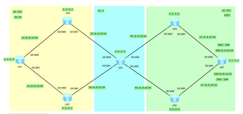
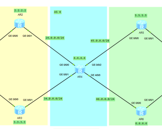
As shown in the figure
There are two user network segments in AS 300
When users in AS 100 access these two network segments
It is hoped to realize traffic sharing on R2 and R3
When AS 200 accesses these two network segments
It is hoped that traffic sharing can be realized on RTE and RTF
Please implement the above requirements in as many ways as possible
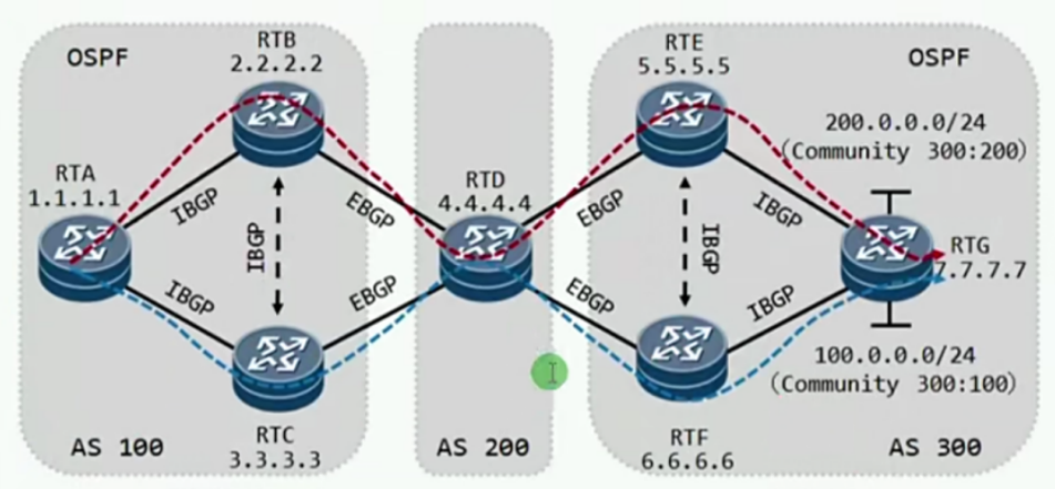
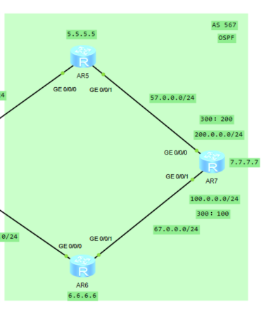
Topology Preview
According to the title
Build AS 123, AS 4, AS 567
AS 123 area configuration IS-IS
OSPF configuration in AS 567 area
(if you haven't learned IS-IS, it doesn't matter. Here you need two link state routing protocols to transfer routing)
Link state routing protocol & distance vector routing protocol
Here is a knowledge point
Have a better understanding of routing protocols
Routing protocols are divided into IGP and EGP
IGP: Interior Gateway Protocol
It includes distance vector routing protocol and link state routing protocol
Link State Routing Protocol
Including OSPF, IS-IS and other protocols
Each router will receive the link status information of all other routers in the routing domain
Each router can create its own network topology and independently calculate the shortest path to each network
Dijkstra algorithm based on SPF shortest path first
Triggered update
Higher resource requirements
Occupy more bandwidth (because of flooding LSA)
Therefore, the size of the routing domain should be controlled to reduce the flooding range
Reduce network load and improve network performance
Distance vector routing protocol
Including rip, EIGRP and other protocols
Do not know the complete topology of the routing domain
Basic cycle update
EIGRP is a Cisco private protocol, which is much better than RIP and belongs to triggered update
External gateway protocol
The most important is BGP protocol
Routing protocol used between AS
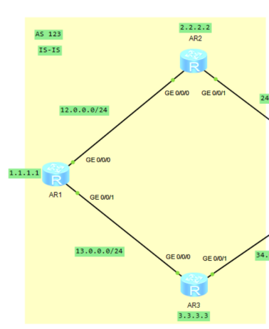
1, Basic configuration
1. Basic configuration of as 123 area and configuration of IS-IS (yellow)
Type the following command in R1:
sys
sys R1
int g0/0/0
ip add 12.0.0.1 24
int g0/0/1
ip add 13.0.0.1 24
int lo 1
ip add 1.1.1.1 32
q
isis 1
network-entity 49.0001.0000.0000.0001.00
is-level level-2
int g0/0/0
isis enable 1
int g0/0/1
isis enable 1
int lo 1
isis enable 1
Type the following command in R2:
sys
sys R2
int g0/0/0
ip add 12.0.0.2 24
int g0/0/1
ip add 24.0.0.2 24
int lo 2
ip add 2.2.2.2 32
q
isis 1
network-entity 49.0002.0000.0000.0002.00
is-level level-2
int g0/0/0
isis enable 1
int g0/0/1
isis enable 1
int lo 2
isis enable 1
Type the following command in R3:
sys
sys R3
int g0/0/0
ip add 13.0.0.3 24
int g0/0/1
ip add 34.0.0.3 24
int lo 3
ip add 3.3.3.3 32
q
isis 1
network-entity 49.0003.0000.0000.0003.00
is-level level-2
int g0/0/0
isis enable 1
int g0/0/1
isis enable 1
int lo 3
isis enable 1
2. Basic configuration of as 4 area (blue)
Type the following command in R4:
sys
sys R4
int g0/0/0
ip add 24.0.0.4 24
int g0/0/1
ip add 34.0.0.4 24
int g0/0/2
ip add 45.0.0.4 24
int g4/0/0
ip add 46.0.0.4 24
int lo 4
ip add 4.4.4.4 32
3. Basic configuration of as 567 area and OSPF configuration (green)
Type the following command in R5:
sys
sys R5
int g0/0/0
ip add 45.0.0.5 24
int g0/0/1
ip add 57.0.0.5 24
int lo 5
ip add 5.5.5.5 32
q
ospf 1 router-id 5.5.5.5
area 0
net 57.0.0.0 0.0.0.255
net 5.5.5.5 0.0.0.0
Type the following command in R6:
sys
sys R6
int g0/0/0
ip add 46.0.0.6 24
int g0/0/1
ip add 67.0.0.6 24
int lo 6
ip add 6.6.6.6 32
q
ospf 1 router-id 6.6.6.6
area 0
net 67.0.0.0 0.0.0.255
net 6.6.6.6 0.0.0.0
Type the following command in R7:
sys
sys R7
int g0/0/0
ip add 57.0.0.7 24
int g0/0/1
ip add 67.0.0.7 24
int lo 7
ip add 7.7.7.7 32
int lo 100
ip add 100.0.0.1 24
int lo 200
ip add 200.0.0.1 24
q
ospf 1 router-id 7.7.7.7
area 0
net 57.0.0.0 0.0.0.255
net 67.0.0.0 0.0.0.255
net 7.7.7.7 0.0.0.0
2, Configuration of IBGP in AS 123 area
Type the following command in R1:
sys
sys R1
bgp 123
router-id 1.1.1.1
peer 2.2.2.2 as 123
peer 2.2.2.2 con lo 1
peer 2.2.2.2 next-hop-local
peer 3.3.3.3 as 123
peer 3.3.3.3 con lo 1
peer 3.3.3.3 next-hop-local
net 1.1.1.1 32
Type the following command in R2:
sys
sys R2
bgp 123
router-id 2.2.2.2
peer 1.1.1.1 as 123
peer 1.1.1.1 con lo 2
peer 1.1.1.1 next-hop-local
peer 3.3.3.3 as 123
peer 3.3.3.3 con lo 2
peer 3.3.3.3 next-hop-local
net 2.2.2.2 32
Type the following command in R3:
sys
sys R3
bgp 123
router-id 3.3.3.3
peer 1.1.1.1 as 123
peer 1.1.1.1 con lo 3
peer 1.1.1.1 next-hop-local
peer 2.2.2.2 as 123
peer 2.2.2.2 con lo 3
peer 2.2.2.2 next-hop-local
net 3.3.3.3 32
3, Configuration of EBGP
Type the following command in R2:
sys
sys R2
bgp 123
router-id 2.2.2.2
peer 24.0.0.4 as 4
Type the following command in R3:
sys
sys R3
bgp 123
router-id 3.3.3.3
peer 34.0.0.4 as 4
Type the following command in R4:
sys
sys  R4
bgp 4
router-id 4.4.4.4
peer 24.0.0.2 as 123
peer 34.0.0.3 as 123
peer 45.0.0.5 as 567
peer 46.0.0.6 as 567
net 4.4.4.4 32
Type the following command in R5:
sys
sys R5
bgp 567
router-id 5.5.5.5
peer 45.0.0.4 as 4
Type the following command in R6:
sys
sys R6
bgp 567
router-id 6.6.6.6
peer 46.0.0.4 as 4
4, Configuration of IBGP in AS 567 area
Type the following command in R5:
sys
sys R5
bgp 567
router-id 5.5.5.5
peer 6.6.6.6 as 567
peer 6.6.6.6 con lo 5
peer 6.6.6.6 next-hop-local
peer 7.7.7.7 as 567
peer 7.7.7.7 con lo 5
peer 7.7.7.7 next-hop-local
Type the following command in R6:
sys
sys R6
bgp 567
router-id 6.6.6.6
peer 5.5.5.5 as 567
peer 5.5.5.5 con lo 6
peer 5.5.5.5 next-hop-local
peer 7.7.7.7 as 567
peer 7.7.7.7 con lo 6
peer 7.7.7.7 next-hop-local
Type the following command in R7:
sys
sys R7
bgp 567
router-id 7.7.7.7
peer 5.5.5.5 as 567
peer 5.5.5.5 con lo 7
peer 5.5.5.5 next-hop-local
peer 6.6.6.6 as 567
peer 6.6.6.6 con lo 7
peer 6.6.6.6 next-hop-local
net 100.0.0.0 24
net 200.0.0.0 24
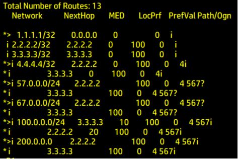
5, Testing
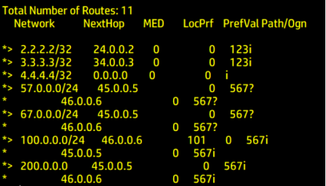
Type the following command in R1 R4 R7:
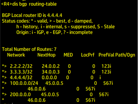
dis bgp routing-table
View BGP routing table
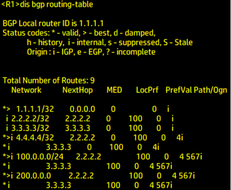
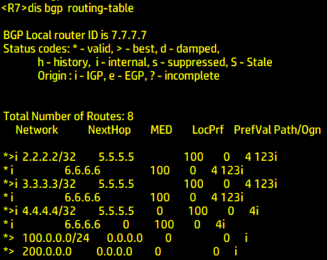
It can be seen from the above
100.0. 0.0/24 and 200.0 0.0/24 network segments arrive at R1 from R7 through R5 R2
Next, we configure the policy
2, BGP group attribute filtering
1 knowledge review
The Community attribute is an optional transition attribute
Identifying BGP routes with the same characteristics makes the application of routing strategy more flexible
Reducing the difficulty of maintenance and management is similar to tagging some routes
1.1 recognized group attributes
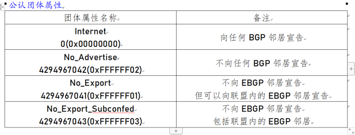
1.2 private group attributes

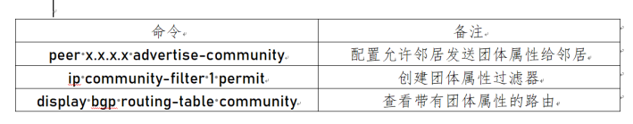
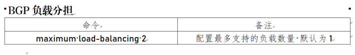
1.3 basic command
2. Policy configuration
2.1 label 100 200 network segments with private group attribute
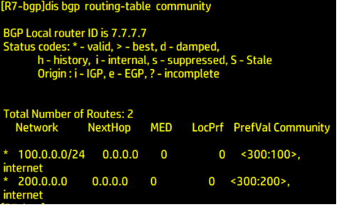
Type the following command in R7:
sys
sys R7
ip ip-pre 100 permit 100.0.0.1 24
route-policy admin permit node 10
if-match interface lo 100
if-match ip-pre 100
apply community 300:100
ip ip-pre 200 permit 200.0.0.1 24
route-policy admin permit node 20
if-match ip-pre 200
if-match interface lo 200
apply community 300:200
route-policy admin permit node 30
bgp 567
peer 5.5.5.5 route-policy admin export
peer 6.6.6.6 route-policy admin export
bgp 567
peer 5.5.5.5 advertise-community
peer 6.6.6.6 advertise-community
Verify labeling
Type the following command in R7:
dis bgp routing-table community
2.2 declare group attributes to IBGP and EBGP
Type the following command in R6
sys
sys R6
bgp 567
peer 46.0.0.4 advertise-community
Type the following command in R5
sys
sys R5
bgp 567
peer 45.0.0.4 advertise-community
Type the following command in R4
sys
sys R4
bgp 4
peer 24.0.0.2 advertise-community
peer 34.0.0.3 advertise-community
Type the following command in R3
sys
sys R3
bgp 123
peer 1.1.1.1 advertise-community
Type the following command in R2
sys
sys R2
bgp 123
peer 1.1.1.1 advertise-community
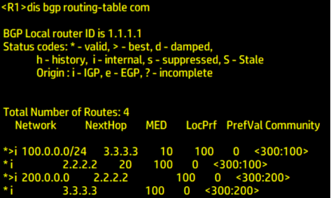
Check whether there is a group attribute tag in R1
Type the following command in R1
dis bgp routing-table community
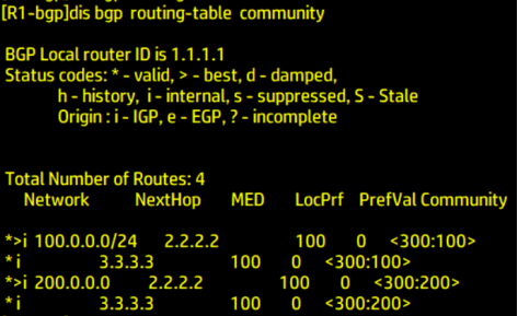
R1: Roger!
2.3 configure group attribute filter
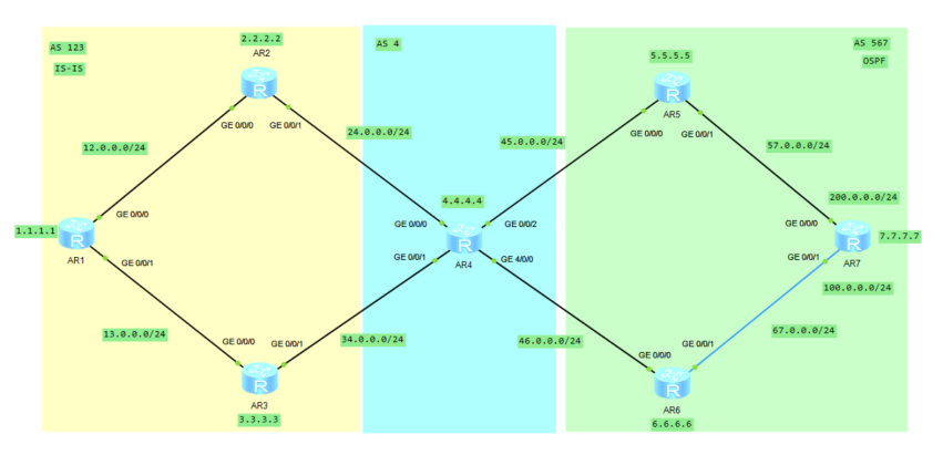
bring
R5-R2 for 200 network segment
100 network segment R6-R3
2.3. Routing of 1 R4
Type the following command in R4
sys
sys R4
ip community-filter 100 permit 300:100
route-policy admin100 permit node 10
if-match community-filter 100
apply local-preference 101
bgp 4
peer 46.0.0.6 route-policy admin100 import
route-policy admin100 permit node 20
View the BGP routing table
Type the following command in R4
dis bgp routing-table
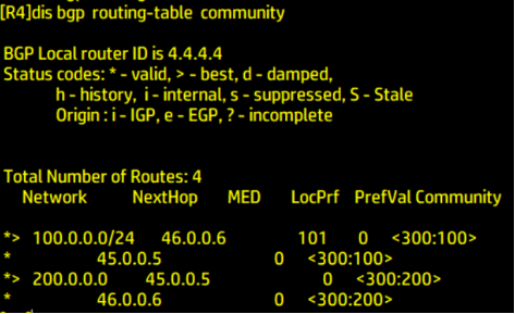
100 network segment according to the configured
apply local-preference 101
Select R6 with higher local priority. The higher the local priority, the higher the priority
2.3. 2 routing of R1
Type the following command in R3
sys
sys R3
ip ip-prefix admin100 permit 100.0.0.1 24
route-policy 100 permit node 10
if-match ip-prefix admin100
apply cost 10
route-policy 100 permit node 20
bgp 123
peer 1.1.1.1 route-policy 100 export
Type the following command in R2
sys
sys R2
ip ip-prefix admin100 permit 100.0.0.1 24
route-policy 100 permit node 10
if-match ip-prefix admin100
apply cost 20
route-policy 100 permit node 20
bgp 123
peer 1.1.1.1 route-policy 100 export
View the BGP routing table
Type the following command in R1
dis bgp routing-table
Here, the MED is modified by modifying the Cost value Cost
For 100 network segments
Change the cost value of R3 to 10
Change the cost value of R2 to 20
apply cost 10/20
The smaller the MED, the better
Configuring the replica topology
More routing methods are available for update... To be continued