1, Introduction (with lunwen and defense PPT)
1 topic content
Metal plate is widely used in all aspects of industrial production and production life. Due to the influence of equipment, process and other factors involved in the metal plate manufacturing process, there are many kinds and different forms of defects on the metal plate surface. These defects will have varying degrees of impact on the wear resistance, corrosion resistance, electromagnetic characteristics and aesthetics of the metal plate, and finally affect the electromagnetic characteristics and coating effect of the metal plate. Therefore, for enterprises producing metal plates, surface defect detection is an essential process. On the one hand, defective products can be detected in time through surface defect detection to ensure the quality of the produced metal plates and maintain the reputation of the enterprise. On the other hand, problems existing in the production process can be found and solved in time by analyzing the detection results [1]. Based on the photo data set of metal surface defects provided on the Internet, we will construct the corresponding algorithm to detect, identify, classify and measure the size of metal surface defects.
1.2 subject requirements
The identification and classification of metal surface defects have the following specific requirements:
(1) According to the characteristics of metal surface defect pictures, appropriate gray transformation (contrast enhancement and filtering) is carried out on the pictures;
(2) The global optimization threshold segmentation of metal surface defect images is carried out;
(3) Extracting boundary coordinates of binary image region;
(4) Feature extraction of metal defects;
(5) Carry out supervised training on the classification of metal defects;
(6) Complete the judgment of metal defect type and the calculation of location and size;
(7) Complete the GUI design of metal defect detection.
2 topic analysis
We learned from relevant data that the common metal surface defects are mainly as follows: fine cracks, surface impurities, patches, pitted surface, rolled in scale and scratches. They correspond to figure (a) - figure (f).
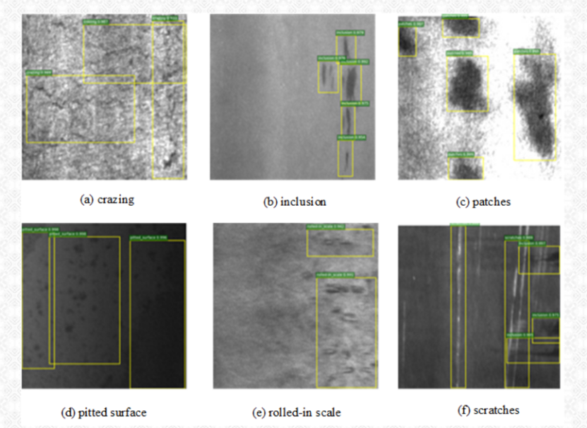
We only consider three types: surface spots (Fig. b), surface rolled in oxide scale (Fig. e)) and surface scratches (Fig. f)).
The main steps of image processing are: contrast enhancement, filtering, threshold segmentation, morphological processing, feature extraction, classification training, defect location and size calculation and GUI integrated operation display.
Step.1: Contrast enhancement
Due to the lighting mode, we found that the gray difference and gray range between the metal surface defect in the original image and the whole metal surface background are small, so the contrast is low and the metal defect is not obvious, which is not conducive to the post-processing of the image. We need to use some methods to increase the contrast of the image. Common contrast enhancement methods include logarithmic transformation, power-law transformation, gray level stratification, gray normalization, contrast stretching, histogram equalization, histogram specification and so on. Considering that the background light intensity of different photos is different, the methods of constant parameters (such as logarithmic transformation, power-law transformation, gray level stratification and contrast stretching) are not applicable to all pictures, so we consider using gray normalization and histogram equalization.
Step.2: Filter processing
When taking photos, various noises will inevitably be introduced in the acquisition process, including Gaussian noise and salt and pepper noise. At the same time, the metal surface itself has a certain texture. Noise and texture will mask metal surface defects to a certain extent, resulting in errors in extraction. We need to filter the image first to reduce subsequent false detection. Filtering methods are mainly divided into spatial domain filtering and frequency domain filtering, and their relationship satisfies the convolution theorem. The spatial filtering mainly includes mean filtering, median filtering, Gaussian filtering and bilateral filtering; Fourier transform and cosine filtering, frequency filtering and discrete filtering. Although these algorithms can reduce noise, they will also filter out some details, resulting in the loss of some defect details. All we need to find new filtering algorithms to implement.
Step.3: Threshold segmentation
After we get the filtered image, we also need to carry out binarization threshold processing to properly extract the defect information. The traditional threshold segmentation needs to determine the threshold, but for different complex metal defect images, we can't use the same threshold for all images. We plan to use global / local optimization threshold segmentation to automatically determine the best threshold.
Step.4: Morphological processing
Limited by the original image quality and image threshold segmentation algorithm, some areas that should be connected in the binary image may be segmented by threshold. For example, a scratch defect may be separated into multiple line segments due to its low gray value. Therefore, we need to perform closed operations to connect adjacent objects. At the same time, some defects in the picture are large (such as large scratch width). After subsequent edge detection, the two edges of a straight line are far apart, and the straight line extraction algorithm will mistakenly treat the same line as two parallel scratches. Therefore, we also need to refine the defects.
Step.5: Feature extraction
Two methods can be used in this part. One is based on general feature extraction algorithms (such as HOG, LBP, Haar algorithm, etc.); The other is to classify the scratches directly based on the specific characteristics of the specific metal defects we want to detect. I will test these two methods separately.
Step.6: Classification training
If we use a general feature extraction algorithm, we will carry out classification supervision training. The commonly used supervised learning algorithms include: K-nearest neighbor algorithm (KNN), naive Bayesian algorithm, decision tree algorithm, support vector machine (svm), logistic regression, etc. Because support vector machine has excellent generalization ability and can get much better results than other algorithms in small sample training set [6], we intend to choose support vector machine algorithm.
Step.7: Defect location and size calculation
After extracting defects, we need different features to characterize the size and location of defects. For 'rolled in oxide scale', we use the number of 'rolled in oxide scale' to characterize the size of defects, and use its centroid to characterize its location; For spots, we use the proportion of the area in the spot to the whole picture to characterize the defect size. For scratches, we use the two end points of scratches to characterize the defect location, and use the scratch length to standard the defect size.
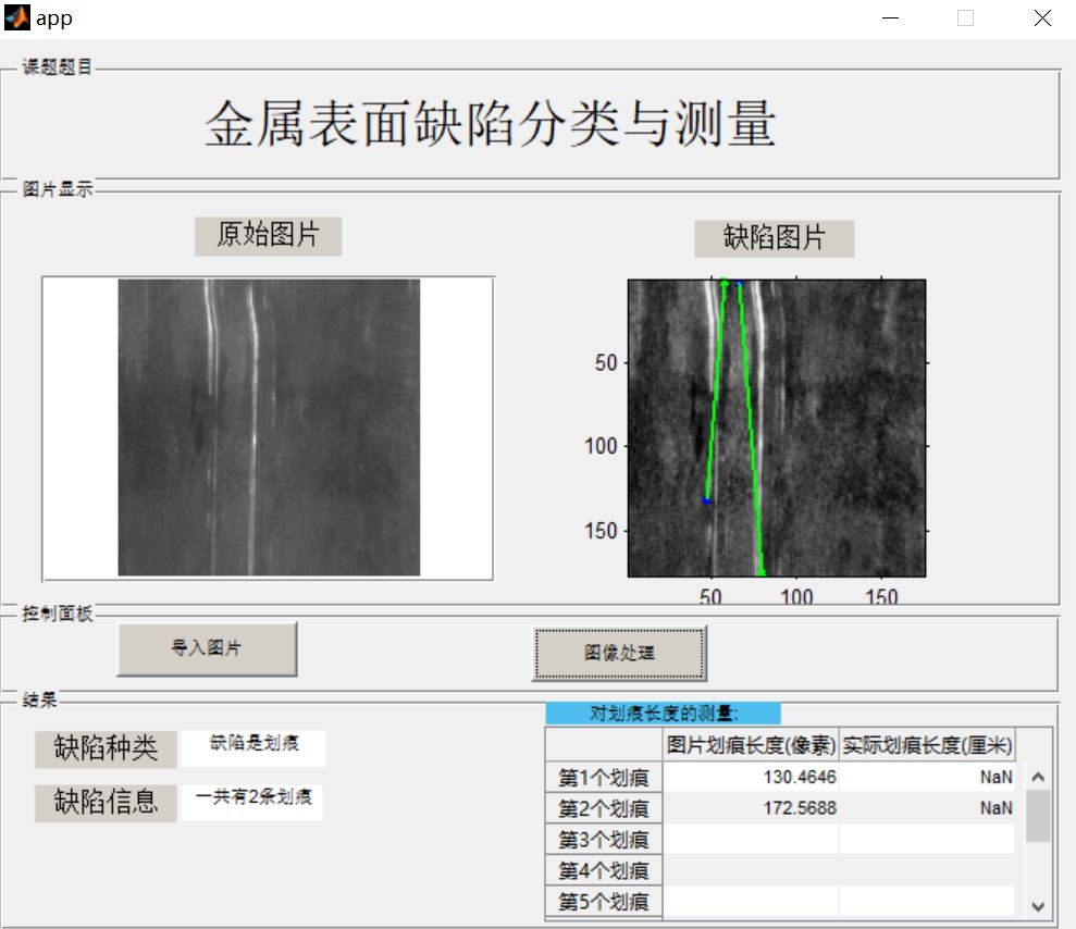
Step.8: GUI design
In order to facilitate users' use, we have designed a GUI interface, which can select the pictures in the computer, and display the extracted defect information (type, position and size) after clicking 'image processing'. For the scratch length, we can allow users to input the focal length and object distance length of the camera, so as to calculate the actual scratch size according to the geometric optics knowledge, The image surface size and actual size of each scratch are displayed. At the same time, the GUI allows users to go to the download website of the dataset by pressing the key.
2, Partial source code
//Work overview:
The main function of this code is to realize the detection, classification and measurement of three kinds of defects on the metal surface GUI Encapsulated for user use.
Should GUI It can import the gray-scale image in the computer and then process it to determine the type of defects and mark the detected defects on the original drawing,
And can measure the size of different defects(Different defect measurement standards are different).
------------------------------------------------------------------------------------------
//Introduction to important functions:
#pushbutton1_Callback(hObject, eventdata,handles):
Key 1(Namely'image processing'Key)Callback function, including all image processing algorithms
#pushbutton2_Callback(hObject, eventdata,handles):
Key 2(Namely'Picture import'Key)Callback function, mainly the import of pictures
#Ga(theta,num): initialization of Gabor convolution kernel of image
#Filterimage (A6, gaborfilter): Gabor filtering algorithm
#Thresh (image): maximum entropy threshold segmentation algorithm for gray image
#location(): location and display of 'rolled in oxide scale' defect
#houghtran(): Hoff circle detection for 'scratch' defects
#lbp(varargin): feature extraction algorithm of 'local binary pattern' on the Internet
#svm.m: Independent m file is used for LBP feature extraction of all metal defect photos and training and testing of SVM (support vector machine) supervised learning algorithm
--------------------------------------------------------------------------------------------

%}


%%
function varargout = app(varargin)
%GUI Page main function, MATLAB Provided without modification

gui_Singleton = 1;
gui_State = struct('gui_Name',       mfilename, ...
                   'gui_Singleton',  gui_Singleton, ...
                   'gui_OpeningFcn', @app_OpeningFcn, ...
                   'gui_OutputFcn',  @app_OutputFcn, ...
                   'gui_LayoutFcn',  [] , ...
                   'gui_Callback',   []);
if nargin && ischar(varargin{1})
   gui_State.gui_Callback = str2func(varargin{1});
end

if nargout
    [varargout{1:nargout}] = gui_mainfcn(gui_State, varargin{:});
else
    gui_mainfcn(gui_State, varargin{:});
end
%%


function app_OpeningFcn(hObject, eventdata, handles, varargin)
% GUI Initialization function
%Modify settings background
%modified by:Faust.Cao

ha=axes('units','normalized','pos',[0 0 1 1]);
 uistack(ha,'down');
 %The background image of the setup program is back.jpg
 ii=imread('C:\Users\lenovo\Desktop\Classification and measurement of metal surface defects GUI system\Metal surface defect classification and measurement system\back.jpg');
 image(ii);
 colormap gray
 set(ha,'handlevisibility','off','visible','off');

handles.output = hObject;
guidata(hObject, handles);
%%


function varargout = app_OutputFcn(hObject, eventdata, handles)
% GUI Output function, MATLAB Provided without modification

varargout{1} = handles.output;
%%


function pushbutton1_Callback(hObject, eventdata, handles)
% Key 1(Namely'image processing'Key)Callback function, including all image processing algorithms

global a5;%global variable
global svmModel;%Global variables, from svm.m File call
axis off;%remove axes Coordinates, full display picture
a6=a5;
a=str2double(get(handles.edit1,'string'));%Read the focal length entered by the user
b=str2double(get(handles.edit2,'string'));%Read the object distance entered by the user

d=a/(b-a);%Calculation of vertical axis magnification by Gauss formula

ma=max(max(a6));
mi=min(min(a6));
%Contrast enhancement, mapping grayscale to[0,255]
for ii=1:200
    for jj=1:200
        a6(ii,jj)=255*double(a6(ii,jj)-mi)./double(ma-mi);
    end
end
%image filtering
ab=filterimage(a6);

%Image maximum entropy threshold segmentation
ss=thres(ab);
ab1=im2bw(ab,ss/255);

[B,L]=bwboundaries(ab1);%Edge coordinate extraction of binary graph
[x,y]=size(B);
mm=0;
%Find the maximum extraction area
for i=1:x
    ll=length(B{i});
    if ll>mm
      mm=ll;
    end
end
%Judge whether it is'Mill scale'defect
if mm<120
 set(handles.text8,'string','The defect is rolling in oxide scale');%stay text8 Output defect type at text box
 [xc,yc]=findcenter(B,ab);%Find the centroid position of each extracted region
 axes(handles.axes2);%Set in axes2 Display at
 imshow(a6);
 hold on;
 plot(yc+12,xc+12,'*');%Add the boundary lost during filtering
 [dd,bb]=size(xc);
 tex=['Altogether',num2str(dd),'More than points'];
 set(handles.text10,'string',tex);%stay text10 Output defect information at the text box
%no'Mill scale'Defect, continue to judge
else
  %Mask the original image and binary image. Pay attention to their different sizes, so the edges of the original image should be removed first
  a6(1:12,:)=[];
  a6(177:188,:)=[];
  a6(:,1:12)=[];
  a6(:,177:188)=[];
  mu1=uint8(ab1).*a6;
  mu2=uint8(1-ab1).*a6;
  t0=mu1(mu1~=0);
  m1=mean(t0);
  t1=mu2(mu2~=0);
  m2=mean(t1);
  %Judge whether the defect is spot or scratch:Spots are darker than the background and scratches are cooler than the background; Compare the mask with the background residual mean
  %You can also extract the image first LBP(Local binary mode)Features, reuse SVM The results of training are classified
  if m1<m2+20
    set(handles.text8,'string','Defects are spots');

    all=bwarea(ab1);%Calculate spot area
    pro=100*all/176/176;%Calculated percentage
    tex=['The area ratio of spots is',num2str(pro),'%'];
    set(handles.text10,'string',tex);
    axes(handles.axes2);
    imshow(a6);
    hold on;
    %Mark the speckle boundary
    for k = 1:length(B)
      boundary = B{k};
      plot(boundary(:,2), boundary(:,1), 'r', 'LineWidth', 2)
    end

  %The defect is a scratch
  else
    a6=adapthisteq(a6);%Adaptive histogram equalization enhances the contrast again
    ss=thres(a6);
    ab1=im2bw(a6,ss/255);

    ab1=imclose(ab1,strel('square',6));%Do a close operation on the binary graph to disconnect some connections
    ab1=bwmorph(ab1,'thin',5);%Refine the binary graph again
    ab1=edge(ab1,'Canny');%use Canny Operator edge extraction
    set(handles.text8,'string','The defect is a scratch');
    axes(handles.axes2);
    imshow(a6);
    hold on;

    %Next is the subsequent processing and display of scratch extraction
    [point,ang]=houghtran( ab1 );%The processed binary image is detected by Hough line

    cen=zeros(length(ang),2);
    po=zeros(length(ang),4);
    an=zeros(length(ang),1);
    thm=mean(abs(ang));
   %Judge whether the scratch is horizontal or vertical(Straight line and y Included angle of shaft)
    if abs(thm)<45%Vertical line
        thm=40;
    else%Horizontal line
        thm=60;
    end

    le=length(cen);
    %Find the midpoint position of each straight line
    for kk=1:le
        cen(kk,1)=(point(kk,1)+point(kk,3))/2;
        cen(kk,2)=(point(kk,2)+point(kk,4))/2;
        point(kk,5)=cen(kk,1);
        point(kk,6)=cen(kk,2);
    end
    %Sort lines by midpoint
    if thm==40%If vertical, sort by abscissa
        point=sortrows(point,5);
    end
3, Operation results

4, matlab version and references
1 matlab version
2014a
2 references
[1] Cai Limei MATLAB image processing -- theory, algorithm and example analysis [M] Tsinghua University Press, 2020
[2] Yang Dan, Zhao Haibin, long Zhe Detailed explanation of MATLAB image processing example [M] Tsinghua University Press, 2013
[3] Zhou pin MATLAB image processing and graphical user interface design [M] Tsinghua University Press, 2013
[4] Liu Chenglong Proficient in MATLAB image processing [M] Tsinghua University Press, 2015