Simulation of PLUTO image communication based on QPSK modulation
West power communication principle operation (it is recommended to debug the code in MATLAB while reading the article, and deeply understand the operation of the system through the conversion of data length and type of variables in the work area)
Specific codes, reports, ppts and demo videos can be downloaded here: https://download.csdn.net/download/yifantan/72861981?spm=1001.2014.3001.5503
1, System design framework
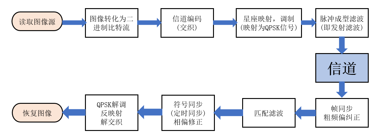
2, Specific working process
We have learned relevant theoretical knowledge in textbooks( If you still need to obtain, go to the third part of the download report to have theoretical knowledge of detailed design ), we further understand the knowledge and how the system works by transforming the data types in the whole system.
1. Convert image to binary bit stream
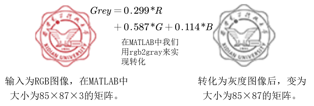
Then, the gray converted image data is converted from decimal to binary, and these data are transformed into a column vector and stored as double type for further processing. eighty-five × eighty-seven × 8=59160
So far, we have changed the image from 85 × eighty-seven × The matrix of 3 is transformed into 1 × 59160 binary bit stream.
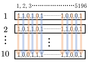
2. Channel coding interleaving
The matintrlv function in MATLAB is used to interleave the bit data, so as to turn a sudden error into a random error and improve the error correction ability. The specific method is to fill the temporary matrix of elements row by row, and then put forward a new 1 × 59160 matrix. The principle is shown in the figure below:
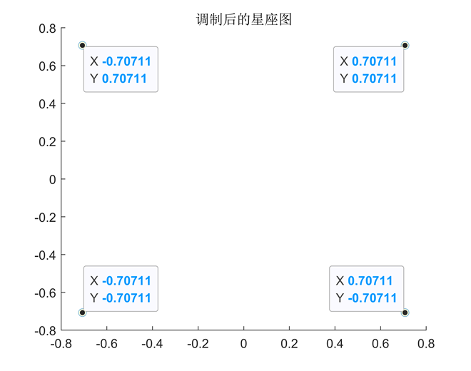
3. Constellation mapping and QPSK modulation
Map the interleaved data into QPSK symbols. The mapping rules are: 00 → 0, 10 → 1, 01 → 2,
11 → 3, so the mapped data is from 1 × 59160 becomes 59160 / 2 = 29580.
The mapped data is added with 100 training symbols for the receiver to correct the frequency offset. (100 ones were added in the experiment) the data became 29680 bits.
QPSK modulation changes the data from a real number to a complex number convenient for transmission, that is, 0 ~ 3 correspond to four complex numbers respectively.
4. Send after pulse shaping filtering
Firstly, 1000 ZC sequences are generated for frame synchronization. Zadoff Chu sequence, named after the authors Solomon Zadoff and David Chu, is used for synchronization and channel detection in LTE. It is widely used because it has constant amplitude, zero cyclic autocorrelation, and the correlation between different sequences is very low.
The modulated data is up sampled, the sampling factor is 20, and the sampled data becomes 29680 × 20 = 593600 bits. After convolution with the designed square root raised cosine filter, the generated ZC sequence is added to the data header, and the data changes from 593600 bits to 594600 bits.
Send data through the device!
5. Receiver works
The receiver receives 1200000 bit s per frame, autocorrelates the received data with the ZC sequence, and finds the starting position of the frame through the autocorrelation characteristics of the ZC sequence.
The comm.CoarseFrequencyCompensator function of MATLAB is used to correct the frequency offset. Using conv convolution function for matched filtering; Use comm.SymbolSynchronizer for symbol synchronization, that is, timing synchronization.
The phase offset is corrected by the phase offset of the previous 100 sequence symbols.
Then the correlation function is used for QPSK demodulation, inverse mapping and interleaving to restore the image.
3, Code simulation and results
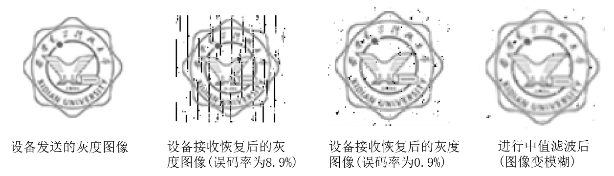
After 200 experiments, the average bit error rate of the system is about 1.96%, and the fluctuation range of bit error rate is small, but there is a sudden increase. The minimum bit error rate in the experiment is 0.90%. The time to receive and restore the image once is about 11 seconds. (note here: the bit error rate is still high. There are improvement steps later, and the effect will be much more obvious after improvement. If you don't want to improve, it will be good to change a smaller picture with overlapping colors to transmit.)
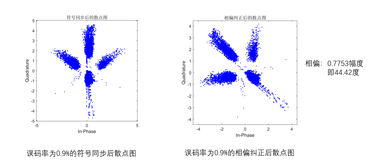
Through the previous training symbols to correct the phase deviation, we can see from the figure below that there is an obvious phase deviation of about 40 ° in the left figure compared with the right figure.
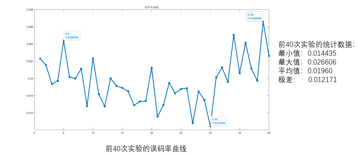
Make statistics on the error rate of the first 40 experiments and draw the error rate curve as follows:
4, Improvement and experience
1. Improvement
The bit error rate of image transmission needs to be below 10-5, and the bit error rate of the system is still high. Further channel coding can be carried out, such as further block interleaving or convolutional interleaving, which can be realized by turbo code; On the other hand, channel estimation and equalization can be carried out to reduce the bit error rate. (note that the latter has a more significant effect on improving the bit error rate; secondly, as mentioned above, it can change simple pictures with smaller color distribution and more concentration).
2. Experience
In this experiment, we do image transmission and reception based on QPSK modulation. We encounter many difficulties in the early stage of the experiment, but we overcome these difficulties by querying data and continuous learning. At the same time, we also realize that there are obvious differences between theoretical learning and practice. We have a deeper understanding of channel coding, pulse shaping filter, frame synchronization, matched filter, phase offset correction and other knowledge, which is convenient for us to further study the theory.
5, References
[1] Li Zhi Frame synchronization method based on CAZAC sequence [J] two thousand and eight
[2] Lin Yongzhao, Wu Chengke, Wang buhong, et al Simplified receiver for continuous phase QPSK modulation [J] Journal of Xi'an University of Electronic Science and technology, 2009, 36 (3): 418-423
| **Transmitter code display** |
%% send_part
% Parameter setting
fs = 100e3; % Sampling rate
sr = 5e3; % chip rate
%%%%%%%%%%%%%%%%%%%%%%%%%Create send object%%%%%%%%%%%%%%%%%%%%%%%%%%%
txPluto = sdrtx('Pluto','RadioID','usb:0','CenterFrequency',800*1e6, ...
    'BasebandSampleRate',fs,'ChannelMapping',1,'Gain',0);
%%%%%%%%%%%%%%%%%%Image data acquisition and coding%%%%%%%%%%%%%%%%%%%%%%%%%%%%%
J1=imread('xidian.png');
J=rgb2gray(J1);
imshow(J);
BinSer=dec2bin(J,8);%Carry out 8 bits pcm code
BinSer=BinSer';%Transpose is convenient for later data processing
str=BinSer(:)' ;%Transform the data matrix into a column vector
leng=length(str);%Length of column vector
b=double(str);%Use one double Type matrix to store column vectors str Data
%Attention here char Direct use of type double Conversion is getting ASCII The value of the code is not the value of 1 and 0, but str2num Cannot be used for matrices, so the following
%Deal with it with a cycle
for i=1:leng
 b(i)=str2double(char(b(i)));
end    %Cycle to complete data conversion

bitData=b;
nBytes = length(str) * 1;
nCode = 1; %8 for one byte bit code

% 2. Interleave
%%%%%%%%%%%%%%%%%Channel coding (interleaving)%%%%%%%%%%%%%%%%%%%%%%%%%%%%%
bitData_scramble = matintrlv(bitData,10*nCode,nBytes/10);   %according to bigData To modify 10->12
  %A sudden error becomes a random error to improve the ability of error correction
% 3. Map to QPSK Symbol
%%%%%%%%%%%%%%%%%Map to QPSK Symbols, modulation%%%%%%%%%%%%%%%%%%%%%%%%%%%%%
symData = QPSKMap(bitData_scramble);
%  Add training symbol
symData = [ones(1, 100), symData];
% 4. modulation
modData = pskmod(symData, 4, pi/4);
figure(2)
scatter(real(modData),imag(modData));
% 5. utilize zc Sequence generation synchronization header
onePreData = CreatZC(500);
preData = repmat(onePreData, 1, 2);
preLength = length(preData);

% 6. Add pilot to correct phase deviation
totalData = modData;

% 7. Set transmit filter,Pulse shaping filter

irfn = 8;%;;Symbol range truncated by filter
ipoint = fs/sr;%Number of points sampled in each symbol range 20
alfa = 0.5; % It can be concluded that the bandwidth is 10 e3 * (1.5) = 15e3;
sendFilter = rcosdesign(alfa, irfn, ipoint, 'sqrt');
delay = irfn * ipoint / 2;
upData = upsample(totalData, ipoint);%The correct results can only be obtained by up sampling
toSend = conv(upData, sendFilter,'same');
%figure(2);
%plot(toSend);
%title('send waveform');
%grid on;

 %%%%%%%%%%%%%%%%pluto The data to be sent is a column vector%%%%%%%%%%%%%%%%%%%%

toSend=[preData toSend];
toSend=toSend.';
%scatterplot(toSend);
%title('Scatter plot of transmitted data');
txPluto.transmitRepeat(toSend);%toSend
% while(true)
%txPluto(toSend);
%end
| **ZC sequence generation code** |
%generate CAZAC sequence
function [cazac_sequence]=CreatZC(signal_length)
%Parameter description
%signal_length CAZAC Generation length of sequence
%cazac_sequence Generated CAZAC sequence
K=1;
n=1:signal_length;
if mod(signal_length,2)==0
    cazac_sequence=exp(1j*2*pi*K/signal_length*(n.*n/2+n));
else
    cazac_sequence=exp(1j*2*pi*K/signal_length*(n.*(n+1)/2+n));
end
end
Specific codes, reports, ppts and demo videos can be downloaded here: https://download.csdn.net/download/yifantan/72861981?spm=1001.2014.3001.5503