catalogue
5. Serial port configuration (asynchronous transceiver)
1. Experiment contents and steps:
1. Clock and GPIO configuration
3. USART1 RX interrupt configuration
5. Program design (Standard Library)
1. Clock and GPIO configuration
1.2 GPIO: (see Chapter 1 and 2 for details)
6. Program design (HAL Library)
1. Clock and GPIO configuration
1.1 clock: (in stm32f1xx_hal_uart.h file)
1.2 GPIO: (stm32f1xx_hal_gpio.c)
3. USART1 sends and receives data
5. Serial port configuration (asynchronous transceiver)
1. Experiment contents and steps:
Experiment content:
Send and receive data (interrupt) through serial port.
Steps:
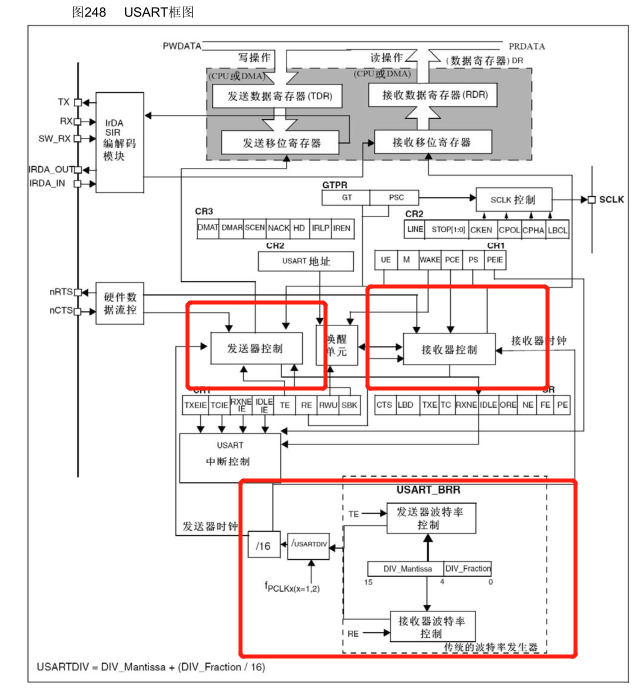
Configure according to UASRT block diagram.
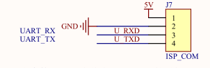
2. Hardware description
3. Register description
1. Clock and GPIO configuration
Clock:
The clock includes TX (PA9) clock, RX(PA10) clock and UASRT1 clock. According to the reference manual, UASRT, TX (PA9) and RX(PA10) are all hung in APB2, so RCC_ The apb2enr register enables the clock.
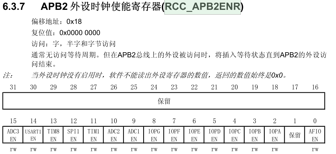
RCC_APB2ENR |= 0x4004; / / enable PA and USART1 clocks
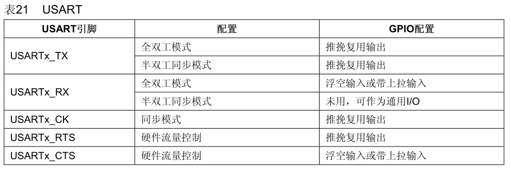
GPIO:
According to the configuration table (STM32 Chinese reference manual P110), using USART1, we need to configure TX (PA10) as push-pull multiplex output and RX(PA9) as floating input or with pull-up input.
To configure PA9 and PA10GPIO, gpiox needs to be configured_ CRH register.
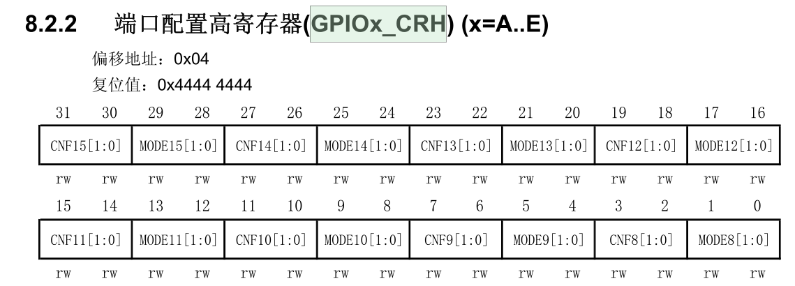
GPIOA_ CRH &= 0xFFFF F00F; / / clear PA9 and PA10 configuration
GPIOA_CRH |= 0x0000 0090; / / TX(PA9) multiplex push-pull output 10M
GPIOA_CRH |= 0x0000 0400; / / RX(PA10) floating input
2. USART1 configuration
USART1 is configured according to USART
2.1 baud rate: baud (115200)
According to the formula:
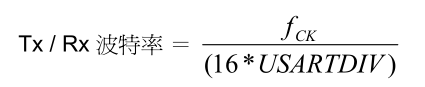
DIV_Mantissa = (integer) Fck/(baud*16);
DIV_Fraction = (integer) (decimal) (Fck/(baud*16) - DIV_Mantissa)*16);
USART_BRR = (DIV_Mantissa<<4)| DIV_Fraction;
2.2 data bit, stop bit and check bit
Data bit (8 bits), check bit (none) through USART_CR1 register configuration. M is word length 0 (8 bits), and PCE is check 0 (Forbidden).
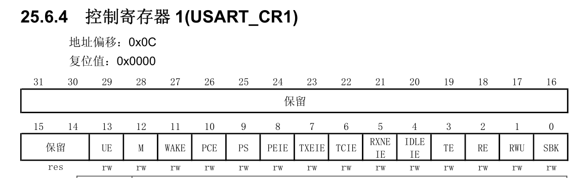
USART_ CR1 &= 0xEBFF; / / (8 data bits, no check bits)
Stop bit (1 bit) via USART_CR2 register configuration, STOP[1:0] is the stop bit. Configured as 00, (1 stop bit)
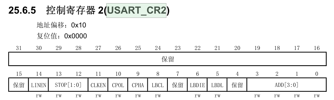
USART_ CR2 &= 0xCFFF; / / 1 stop bit
2.3 USART1, TX, RX enable
USART1 is enabled in USART_ Bit 13 in CR1 register, 1 (enable); TX is SART_ Bit 3 in CR1 register, 1 (enable); RX is SART_ Bit 2 in CR1 register, 1 (enable).
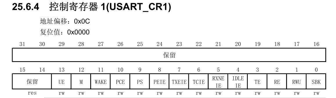
USART_CR1 |= 0x100C; / / USART1, TX, RX enable
2.4 RX interrupt enable
By setting USART_ Bit 5 RXENIE in CR1 register enables RX reception interrupt.
USART_CR1 |= 0x0020; / / RX interrupt enable
3. USART1 RX interrupt configuration
Configuring the interrupt of USART1 requires configuration
3.1 interrupt manager NVIC:
Turn on the interrupt enable through the interrupt enable setting register (NVIC_ISERx) (refer to the M3 authoritative guide, m3 technical reference manual and STM32 M3 programming manual), and according to the interrupt and exception vector table (page P130 of stm32 Chinese reference manual).
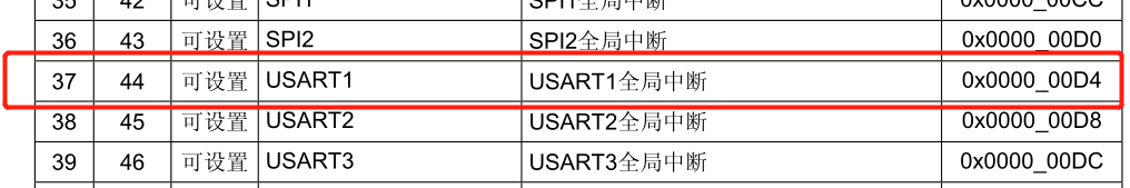
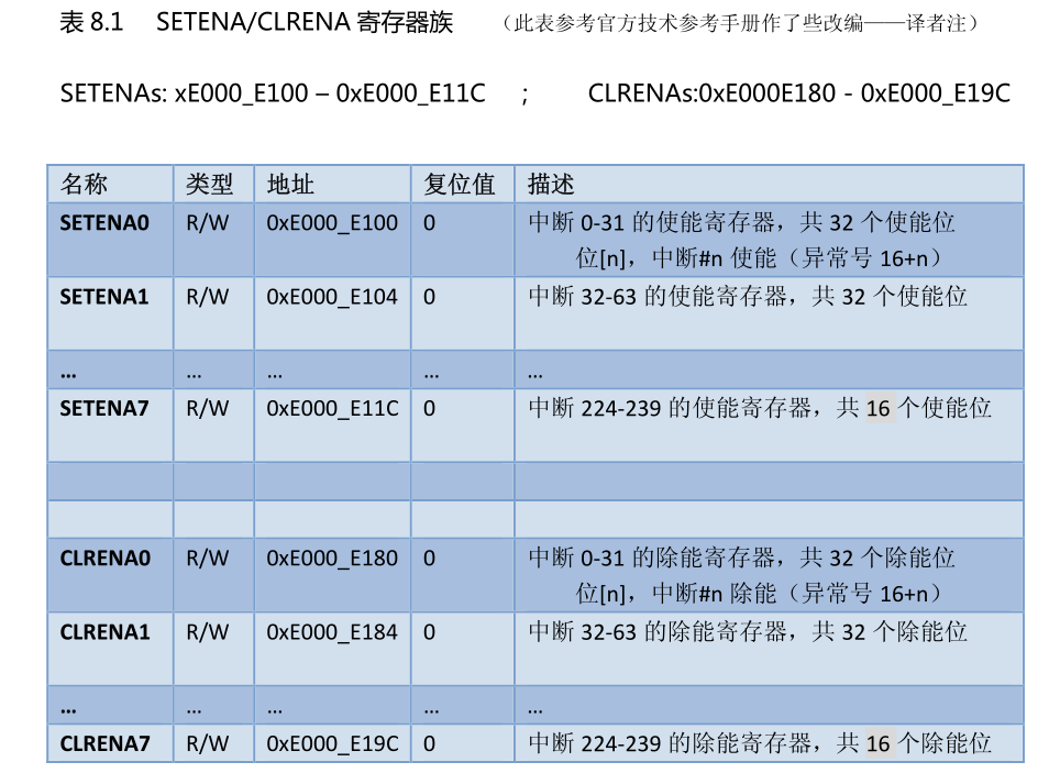
The interrupt vector table position of USART1 is 37, so configure the interrupt manager NVCI to enable USART1, because the 5th bit (37-32) of SETENA1 is configured.
SETENA1 |= 0x0020; / / enable USART1 interrupt in interrupt manager
3.2 interrupt group setting:
At the beginning of the main function, set the interrupt priority group to 4.
3.3 interrupt priority setting:
Priority configuration is divided into response priority and preemption priority according to the configuration of priority group. In the setting of interrupt priority group, the interrupt priority group is set to 4. Therefore, the response priority is 4 bits [7:4] (0-15), and the preemption priority is 0 bits.
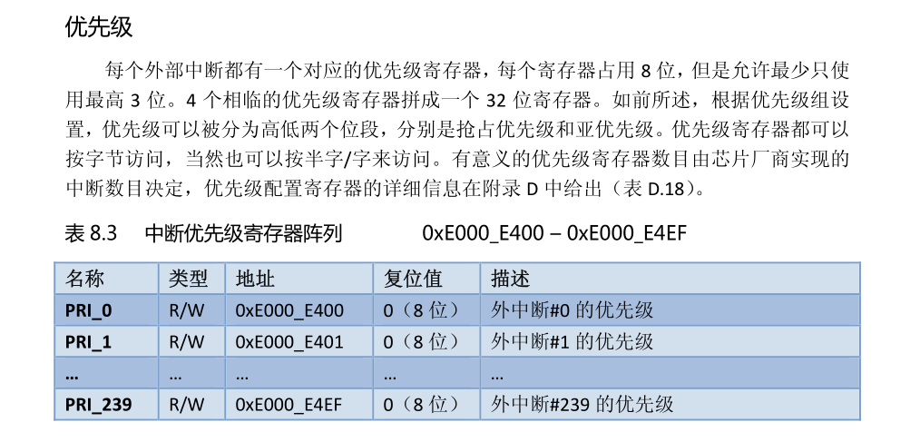
The priority of USART1 is set to 14, so
PRI_37 = 0xE0; s / / USART1 interrupt priority 14
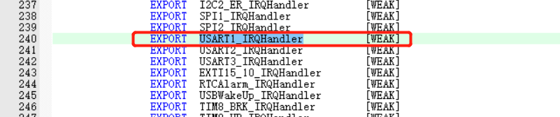
4. USART1 interrupt function
The interrupt function can be used in startup_stm32f10x_hd.s file. USART1 interrupt is used in this experiment, so the name of the interrupt function is USART1_IRQHandler.
Judge whether the carriage return character is received in the interrupt function (\ r\n), and the reception flag position 1 will be received after the reception is completed.
4. Program design (register)
Source code: only some key contents are extracted. See the source code for details
u8 ReadBuf[READ_MAX]={0};
u8 ReadBuf_f=0;
//Clock and GPIO initialization of serial port 1
void USART1_GPIOInit(void)
{
    RCC->APB2ENR |= 0x4004;		//Enable PA, USART1 clock
    GPIOA->CRH &= 0xFFFFF00F;	//Empty PA9, PA10 configuration
    GPIOA->CRH |= 0x00000090;	//TX(PA9) multiplex push-pull output 10M
    GPIOA->CRH |= 0x00000400;	//RX(PA10) float input
}

//Serial port 1 configuration
void USART1_Config(void)
{
    u16 DIV_Mantissa=0,DIV_Fraction=0;
    USART1_GPIOInit();
    DIV_Mantissa = (double)SYSCLK/(115200*16);
    DIV_Fraction = (((double)SYSCLK/(115200*16) - (u16)DIV_Mantissa)*16);
    //Baud rate
    USART1->BRR = ((u16)DIV_Mantissa<<4)| (u16)DIV_Fraction;    //115200
    //Data bit, stop bit, check bit
    USART1->CR1 &= 0x2BFF;		//Data bit: 8 bits, no check bit
    USART1->CR2 &= 0xCFFF;		//1 stop bit
    //USART1, TX, RX enable
    USART1->CR1 |= 0x200C;		// USART1, TX, RX enable
    USART1->CR1 |= 0x0020;      //Receive interrupt

    //NVIC interrupt configuration USART1 37
    NVIC->ISER[1] |= 1<<5;    //Enable NVIC interrupt line USART1
    NVIC->IP[37]    =   0xF0;   //Priority is 16
}

//Send single character
void USART1_Send(u8 ch)
{
    USART1->DR = ch;
    while(!(USART1->SR&0x0080));
}

//Send string
void USART1_Sends(u8 *chs)
{
    while(*chs)
    {
        USART1_Send(*chs);
        chs++;
    }
}


//Interrupt function
void USART1_IRQHandler()
{
    static u16 num=0;
    if(USART1->SR&(1<<5))   //Receive non empty
    {
        ReadBuf[num] = USART1->DR;

        if((ReadBuf[num-1]=='\r')&&(ReadBuf[num]=='\n'))
        {
            num=0;
            ReadBuf_f=1;
        }
        else
            num++;
        if(num>=READ_MAX)   num=0;
    }
}

//Main function
int main(void)
{
  SCB->AIRCR = 0x05FA0300;    //Set priority group 4
  USART1_Config();      //Serial port 1 configuration 115200
  USART1_Sends((u8*)"USART1 test\r\n");
  while (1)
  {
      if(ReadBuf_f==1)
      {
        ReadBuf_f=0;
        USART1_Sends(ReadBuf);
      }
  }
}
5. Program design (Standard Library)
1. Clock and GPIO configuration
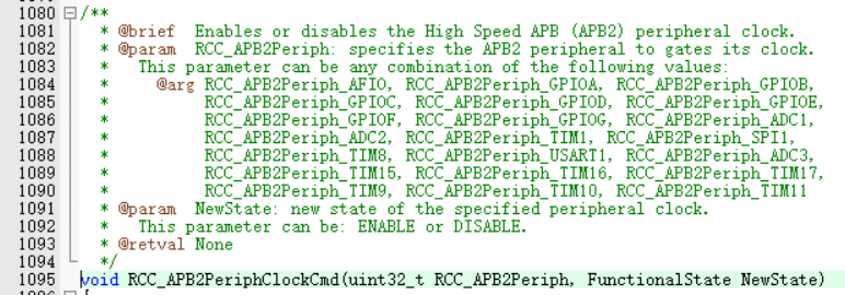
1.1 clock:
Enable GPIOA and USART1 clocks through APB2 clock initialization function.
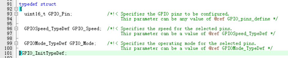
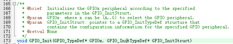
1.2 GPIO: (see Chapter 1 and 2 for details)
Initialization TX (PA9) is a multiplexed push-pull output and RX (PA10) is a floating input. Set TX and RX pins according to GPIO initialization structure and GPIO initialization function.
Structure:
Initialization function:
2. USART1 configuration
2.1 USART1 configuration
USART1 configuration mainly includes data bit, stop bit, check bit, hardware flow, etc. For the attribute configuration of USART1, see the USART1 configuration structure, which is written to the register when calling the initialization structure.
USART1 configuration structure:
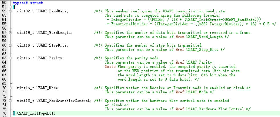
USART_BaudRate; Baud rate (115200)
USART_WordLength; Data bits (8 bits)
USART_StopBits; Stop bit (1 bit)
USART_Parity; Check bit (none)
USART_Mode; Mode (TX/RX)
USART_HardwareFlowControl; Hardware stream (none)
Initialization function:
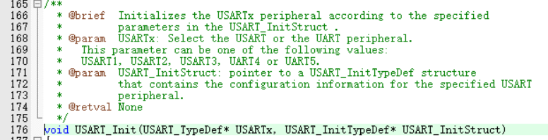
The first parameter is USARTX (1-5), and the second parameter is the initialization structure pointer of USART.
2.2 RX interrupt enable
USART1 mainly uses the receiving interrupt of USART1. Open the interrupt through the following function.
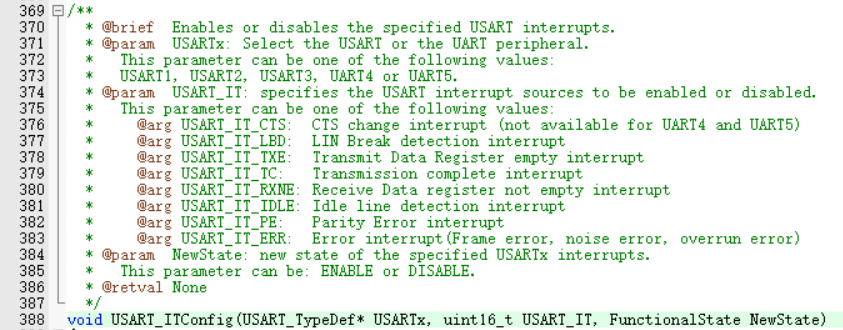
The first parameter is USARTX (1-5); The second parameter is the on interrupt, where the received interrupt is (USART_IT_RXNE); The third parameter is whether to turn on, ENABLE.
2.3 RX interrupt priority configuration
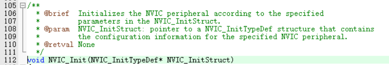
RX interrupt priority is configured through NVIC structure and initialization function.
Structure:
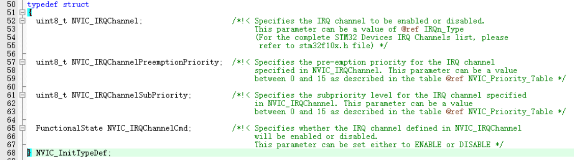
NVIC_IRQChannel; IRQ channel (USART1_IRQ)
NVIC_IRQChannelPreemptionPriority; Response priority
NVIC_IRQChannelSubPriority; Preemption priority
NVIC_IRQChannelCmd; Enable / disable
Initialization function:
2.4 USART1 enable
Enable function via USART1
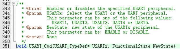
The first parameter is USARTx (1-5); The second parameter is enable / disable
2.5 USART1 interrupt function
The interrupt function of USART1 is USART1_IRQHandler, available in startup_ stm32f10x_ hd. Found in s file.
3. USART1 sends data
3.1 sending characters
Send the characters through the sending function and determine whether to send the function.
Send function:
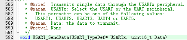
The first parameter is USARTx(1-5); The second parameter is the data sent.
Flag bit acquisition function:
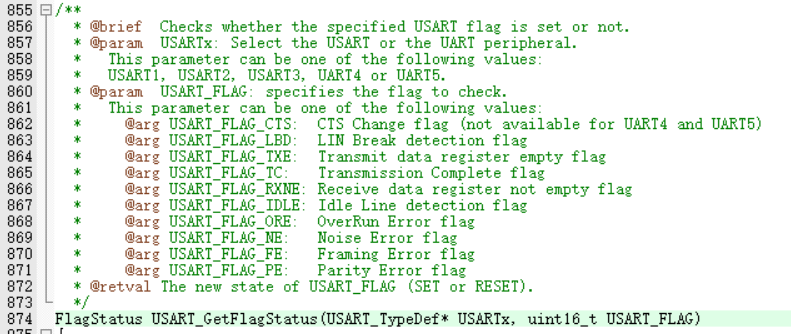
The first parameter is USARTx(1-5); The second parameter is the obtained flag bit, and the transmission completion flag bit is USART_FLAG_TXE.
3.2 send string
Circular transmission of characters can realize the transmission of strings (see source code)
3.3 interrupt receiving callback:
Receive USART1 data through interrupt. When carriage return (\ r\n) is detected, the reception is completed and sent to the computer through USART1.
In the interrupt function, obtain the receive interrupt flag bit, judge whether to receive the interrupt, and if so, read and save the data.
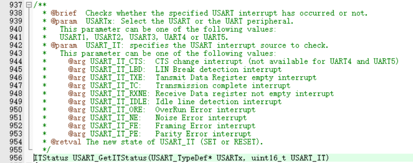
The first parameter is: USARTx(1-5); The second parameter is the obtained interrupt flag bit. Here, the received flag bit is obtained. The received flag bit is USART_IT_RXNE. Since the receiving flag bit can be cleared by reading the receiving register, there is no need to clear the receiving flag bit.
4. Source code:
#include "My_usart1.h"
#include "My_rcc.h"

u8 ReadBuf[READ_MAX]={0};
u8 ReadBuf_f=0;

#define USART1_ RCC_ CLK         RCC_ APB2Periph_ Usart1 / / usart1 clock enable
#define USART1_ RCC_ GPIO_ CLK    RCC_ APB2Periph_ Gpioa / / usart1 GPIO clock enable
#define USART1_GPIO            GPIOA                       //USART1 GPIOA

#define TX1_ PIN          GPIO_ Pin_ 9 / / TX1 pin
#define TX1_ MODE         GPIO_ Mode_ AF_ PP / / TX1 multiplex push-pull output
#define TX1_ SPEED        GPIO_ Speed_ 10MHz / / TX1 speed 10MHz

#define RX1_ PIN          GPIO_ Pin_ 10 / / rx1 pin
#define RX1_ MODE         GPIO_ Mode_ IN_ Floating / / rx1 floating input


#define USART1_EXTIX_IRQ           USART1_IRQn / / key interrupt number
#define USART1_ PP 14 / / key response priority
#define USART1_ SP 0 / / key preemption priority
#define USART1_IRQHandler          USART1_IRQHandler / / press the key to interrupt the function

//Clock and GPIO initialization of serial port 1
void USART1_GPIOInit(void)
{
    GPIO_InitTypeDef GPIO_InitStruct;
    RCC_APB2PeriphClockCmd(USART1_RCC_GPIO_CLK,ENABLE);    //Enable GPIO clock
    RCC_APB2PeriphClockCmd(USART1_RCC_CLK,ENABLE);    //Enable SART1 clock
    //TX1
    GPIO_InitStruct.GPIO_Pin    =   TX1_PIN;    //PIN
    GPIO_InitStruct.GPIO_Mode   =   TX1_MODE;   //pattern
    GPIO_InitStruct.GPIO_Speed  =   TX1_SPEED;  //speed
    GPIO_Init(USART1_GPIO,&GPIO_InitStruct);
    //RX1
    GPIO_InitStruct.GPIO_Pin    =   RX1_PIN;    //PIN
    GPIO_InitStruct.GPIO_Mode   =   RX1_MODE;   //pattern
    GPIO_Init(USART1_GPIO,&GPIO_InitStruct);
}

//Serial port 1 configuration
void USART1_Config(void)
{
    USART_InitTypeDef   USART_InitStruct;
    NVIC_InitTypeDef NVIC_InitStruct;
    USART1_GPIOInit();
    //USART1
    USART_InitStruct.USART_BaudRate =   115200; //Baud rate
    USART_InitStruct.USART_WordLength  =   USART_WordLength_8b;
    USART_InitStruct.USART_StopBits =   USART_StopBits_1;
    USART_InitStruct.USART_Parity   =   USART_Parity_No;
    USART_InitStruct.USART_Mode =   USART_Mode_Rx | USART_Mode_Tx;
    USART_InitStruct.USART_HardwareFlowControl  =   USART_HardwareFlowControl_None;

    USART_Init(USART1,&USART_InitStruct);   //USART1 initialization configuration

    USART_ITConfig(USART1,USART_IT_RXNE,ENABLE);    //Receive interrupt enable

    NVIC_InitStruct.NVIC_IRQChannel     =   USART1_EXTIX_IRQ;         //trunk
    NVIC_InitStruct.NVIC_IRQChannelCmd  =   ENABLE;                     //Enable
    NVIC_InitStruct.NVIC_IRQChannelPreemptionPriority   =   USART1_PP; //Priority 16 minimum
    NVIC_InitStruct.NVIC_IRQChannelSubPriority          =   USART1_SP;
    NVIC_Init(&NVIC_InitStruct);    //Set interrupt priority

    USART_Cmd(USART1,ENABLE);               //USART1 enable
}

//Send single character
void USART1_Send(u8 ch)
{
    while(USART_GetFlagStatus(USART1,USART_FLAG_TXE)!=SET);       //Send completion judgment
    USART_SendData(USART1,ch);
}

//Send string
void USART1_Sends(u8 *chs)
{
    while(*chs)
    {
        USART1_Send(*chs);
        chs++;
    }
}


//Interrupt function
void USART1_IRQHandler()
{
    static u16 num=0;
    if(USART_GetITStatus(USART1,USART_IT_RXNE)!=RESET)   //Receive non empty
    {
        ReadBuf[num] = USART1->DR;

        if((ReadBuf[num-1]=='\r')&&(ReadBuf[num]=='\n'))    //Judge receive \ r\n
        {
            ReadBuf[num+1]='\0';
            num=0;
            ReadBuf_f=1;

        }
        else
            num++;
        if(num>=READ_MAX)   num=0;
    }
}

//Main function
int main(void)
{
  NVIC_PriorityGroupConfig(NVIC_PriorityGroup_4);   //Set interrupt priority group 4
  USART1_Config();      //Serial port 1 configuration 115200
  USART1_Sends((u8*)"USART1 test\r\n");
  while (1)
  {
      if(ReadBuf_f==1)
      {
        ReadBuf_f=0;
        USART1_Sends(ReadBuf);
      }
  }
}
6. Program design (HAL Library)
1. Clock and GPIO configuration
1.1 clock: (in stm32f1xx_hal_uart.h file)
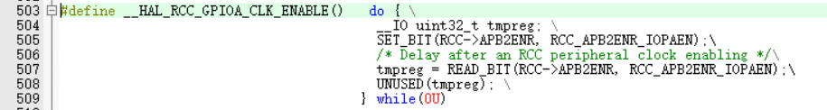
GPIOA clock initialization:
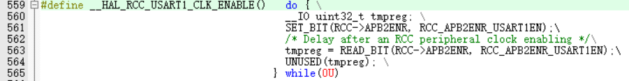
USART1 clock initialization:
1.2 GPIO: (stm32f1xx_hal_gpio.c)
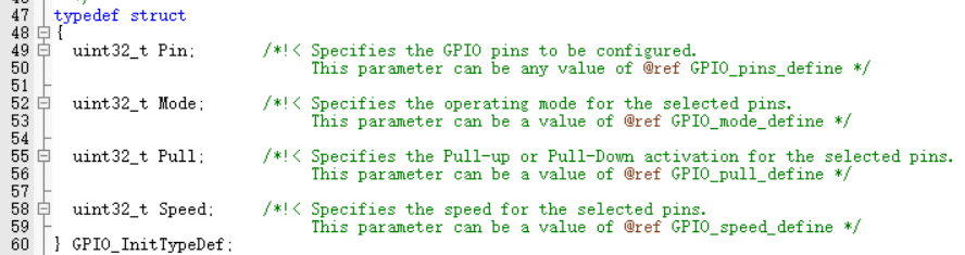
Pin: the GPIO pin that needs to be initialized
Mode: GPIO mode
Pull: pull-down mode
Speed: GPIO output speed
In this experiment, TX (PA9) is set as multiplexed push-pull output and RX(PA10) is set as floating input.
2. USART1 configuration
2.1 USART1 configuration
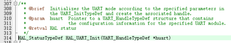
(stm32f1xx_hal_uart.c)
Configure UART_HandleTypeDef structure and call the initialization function.
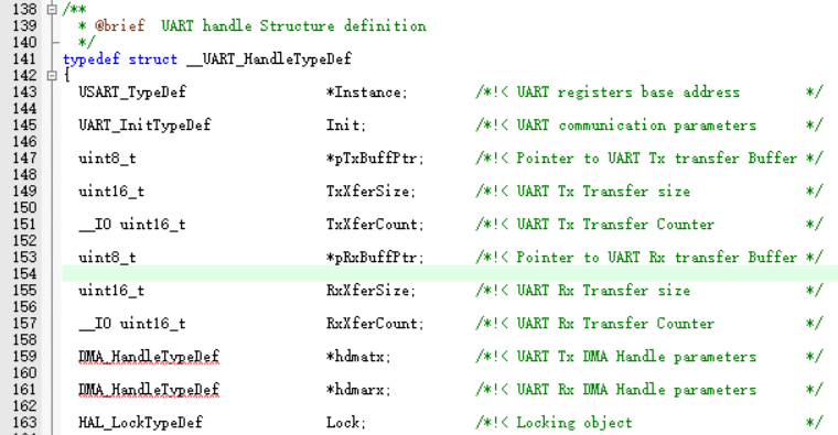
UART_HandleTypeDef structure mainly needs to be configured with two items, * Instance and Init.
* Instance: USARTx(1-5)
Init: UART_InitTypeDef structure
BaudRate: baud rate (115200)
WordLength: data bit length (8 bits)
StopBits: stop bit (1 bit)
Parity: parity bit (none)
Mode: TX/RX
HwFlowCtl: hardware flow (none)
OverSampling: sampling (no tube)
Initialization function
2.2 RX interrupt enable
(stm32f1xx_hal_uart.h)
Another method is used in HAL library. Calling the receive or send function with IT will automatically open the interrupt to receive or send. Therefore, there is no need to enable / open TX/RX interrupt manually.
2.3 interrupt priority configuration
Interrupt priority:
(stm32f1xx_hal_cortex.c)
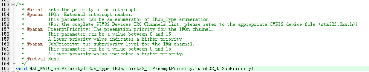
The first parameter is the IRQ number for setting interrupt priority, and USART1 is (37); The second parameter is response priority; The third parameter is preemptive priority.
Enable USART1 interrupt management of NVIC:
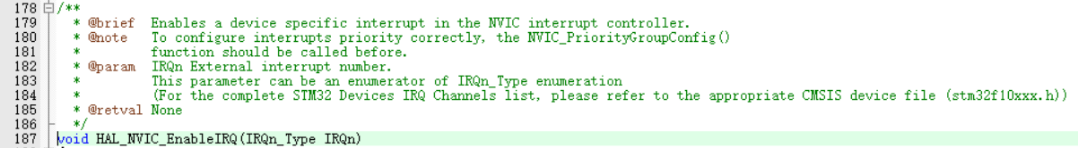
The first parameter is the IRQ number for setting interrupt priority, and USART1 is (37);
2.4 enable RX reception
(stm32f1xx_hal_uart.h)
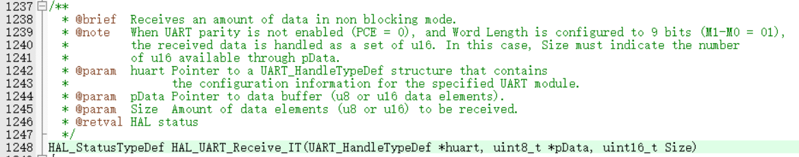
This receiving function is an interrupt receiving operation, which enables the corresponding interrupt receiving configuration. The first parameter is the handle of USART1 (that is, the configuration structure of USART1); The second parameter is the address where the data is saved; The third parameter is the quantity received (1 is recommended).
2.5 USART1 interrupt function
The interrupt function of USART1 is USART1_IRQHandler, available in startup_ stm32f10x_ hd. Found in s file.
In the interrupt function, call the following functions uniformly to judge the total flag bit.
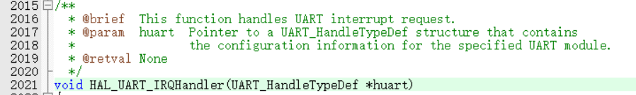
The first parameter is the USART1 handle (that is, the configuration structure of USART1). This function judges and clears the total flag bit. After clearing, it will enter the corresponding receive interrupt callback function (HAL_UART_RxCpltCallback), send interrupt callback function, etc.
3. USART1 sends and receives data
3.1 send string
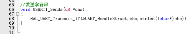
Calling HAL_ in the sending string UART_ Transmit_ It function, which sends the string through an interrupt.
The same is true for sending characters. Just change "strlen((cahr*)chs)" to 1.
3.2 interrupt receiving callback:
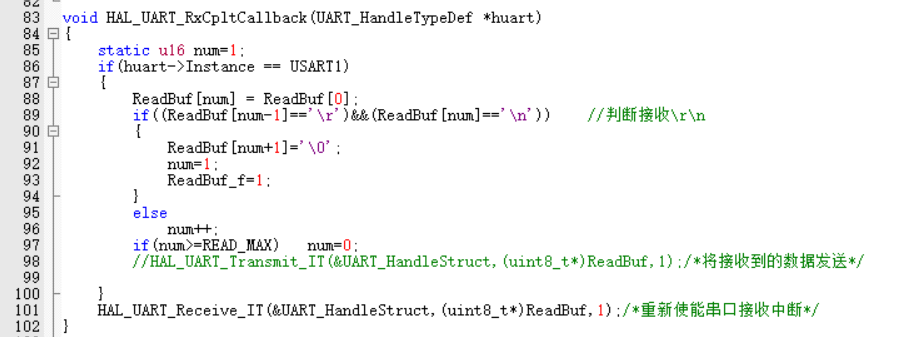
In the receive interrupt callback function, judge the carriage return (\ r\n). The received carriage return represents the completion of data reception and is output in the main function. After the receiving callback function completes processing, it is necessary to restart the receiving.
4. Source code:
u8 ReadBuf[READ_MAX]={0};
u8 ReadBuf_f=0;

#define USART1_ RCC_ CLK         __ HAL_ RCC_ USART1_ CLK_ Enable / / usart1 clock enable
#define USART1_ RCC_ GPIO_ CLK    __ HAL_ RCC_ GPIOA_ CLK_ Enable / / usart1 GPIO clock enable
#define USART1_GPIO            GPIOA                       //USART1 GPIOA

#define TX1_ PIN          GPIO_ PIN_ 9 / / TX1 pin
#define TX1_ MODE         GPIO_ MODE_ AF_ PP / / TX1 multiplex push-pull output
#define TX1_ SPEED        GPIO_ SPEED_ FREQ_ Medium / / TX1 speed 10MHz

#define RX1_ PIN          GPIO_ PIN_ 10 / / rx1 pin
#define RX1_ MODE         GPIO_ MODE_ Input / / rx1 input
#define RX1_ PULL         GPIO_ Nopull / / rx1 floating

#define USART1_IRQ                  USART1_IRQn / / key interrupt number
#define USART1_ PP 14 / / key response priority
#define USART1_ SP 0 / / key preemption priority
#define USART1_IRQHandler          USART1_IRQHandler / / press the key to interrupt the function


//Clock and GPIO initialization of serial port 1
void USART1_GPIOInit(void)
{
    GPIO_InitTypeDef GPIO_InitStruct;

    USART1_RCC_GPIO_CLK();       //Enable GPIOA clock
    USART1_RCC_CLK();      //Enable USART1 clock
    //TX1
    GPIO_InitStruct.Pin     =   TX1_PIN;
    GPIO_InitStruct.Mode    =   TX1_MODE;
    GPIO_InitStruct.Speed   =   TX1_SPEED;
    HAL_GPIO_Init(USART1_GPIO,&GPIO_InitStruct);              //Initialize configuration function
    //RX1
    GPIO_InitStruct.Pin     =   RX1_PIN;
    GPIO_InitStruct.Mode    =   RX1_MODE;
    GPIO_InitStruct.Pull    =   RX1_PULL;
    HAL_GPIO_Init(USART1_GPIO,&GPIO_InitStruct);              //Initialize configuration function
}
UART_HandleTypeDef UART_HandleStruct;
//Serial port 1 configuration
void USART1_Config(void)
{
    USART1_GPIOInit();  //GPIO initialization
    //USART1
    UART_HandleStruct.Instance      =   USART1;
    UART_HandleStruct.Init.BaudRate =   115200;
    UART_HandleStruct.Init.WordLength   =   UART_WORDLENGTH_8B;
    UART_HandleStruct.Init.StopBits     =   UART_STOPBITS_1;
    UART_HandleStruct.Init.Parity       =   UART_PARITY_NONE;
    UART_HandleStruct.Init.Mode         =   UART_MODE_TX_RX;
    UART_HandleStruct.Init.HwFlowCtl    =   UART_HWCONTROL_NONE;
    HAL_UART_Init(&UART_HandleStruct);

    HAL_NVIC_SetPriority(USART1_IRQ,15,0);          //Response priority is 16 min
    HAL_NVIC_EnableIRQ(USART1_IRQ);                 //Enable medium break
    HAL_UART_Receive_IT(&UART_HandleStruct,(uint8_t*)ReadBuf,1);    /*Re enable serial port receive interrupt*/
}

//Send character
void USART1_Send(u8 ch)
{
    HAL_UART_Transmit_IT(&UART_HandleStruct,&ch,1);
}

//Send string
void USART1_Sends(u8 *chs)
{
    HAL_UART_Transmit_IT(&UART_HandleStruct,chs,strlen((char*)chs));
}


//Interrupt function
void USART1_IRQHandler()
{
    HAL_UART_IRQHandler(&UART_HandleStruct);
}

void HAL_UART_RxCpltCallback(UART_HandleTypeDef *huart)
{
    static u16 num=1;
    if(huart->Instance == USART1)
    {
        ReadBuf[num] = ReadBuf[0];
        if((ReadBuf[num-1]=='\r')&&(ReadBuf[num]=='\n'))    //Judge receive \ r\n
        {
            ReadBuf[num+1]='\0';
            num=1;
            ReadBuf_f=1;
        }
        else
            num++;
        if(num>=READ_MAX)   num=0;
        //HAL_ UART_ Transmit_ IT(&UART_HandleStruct,(uint8_t*)ReadBuf,1);/* Send the received data*/

    }
    HAL_UART_Receive_IT(&UART_HandleStruct,(uint8_t*)ReadBuf,1);/*Re enable serial port receive interrupt*/
}

int main(void)
{
  HAL_Init();
  /* Configure the system clock to 72 MHz */
  SystemClock_Config();
  /* Add your application code here */
  USART1_Config();      //Serial port 1 configuration 115200
  USART1_Sends((u8*)"USART1 test\r\n");
  /* Infinite loop */
  while (1)
  {
      if(ReadBuf_f==1)
      {
        ReadBuf_f=0;
        USART1_Sends(ReadBuf);
      }
  }
}
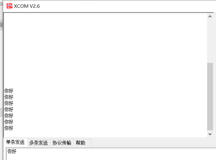
7. Experimental results
When just powered on, the serial port assistant will output "USART1 test"
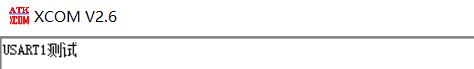
When "Hello \ r\n" is sent, the serial port assistant will also receive it