1, Brief introduction of handwritten capital letter recognition technology
0 Introduction
In the teaching process of colleges and universities, examination is the most common teaching means of teaching evaluation and comprehensive practice. With the progress of science and technology, the way of examination marking has also undergone great changes. The traditional marking method is mainly manual marking, which has some shortcomings, such as low efficiency and so on; Modern marking method adopts optical mark recognition (OMR) technology. Candidates only need to fill in the answer card, and the computer will process the answer card to realize automatic marking, but this method needs to use specially designed answer card and pencil, and follow certain filling specifications. The above two methods have brought certain restrictions to teachers and examinees and cost more time; Therefore, in order to make the subjects answer questions flexibly and efficiently, it is very necessary to study the character recognition of hand writing.
According to the technical route adopted, handwritten character recognition can be divided into two categories: one is feature extraction; The other is neural network method. Feature extraction methods can be divided into two categories according to the different extracted character features: one is the character recognition algorithm based on contour and structural features. This kind of algorithm refines the characters by identifying the contour features, endpoint features and concave convex structural features of the character image, and realizes the automatic recognition of handwritten characters by template matching. Although this kind of method can intuitively describe the structure of characters, it can not recognize the characters with noise and deformation, and is lack of robustness.
The other is handwritten character recognition algorithm based on statistical features. This kind of algorithm trains corresponding classifiers for a large number of samples, and uses these classifiers to classify the characters to be recognized. The advantage is that when the sampling samples are sufficient, this kind of method can have better recognition effect; The disadvantage is that we often can't construct enough samples. The neural network method has a high recognition rate, but it needs to train a large number of samples, which consumes more time and reduces the real-time performance of recognition; Even if the neural network is improved and optimized, it does not fundamentally make up for its shortcomings.
In the examination, due to the different writing styles of the subjects, the handwritten characters have different characteristics, which determines that A single scheme will not get A good recognition effect in the recognition of handwritten characters. In the evaluation of objective questions, most of them only contain four characters A, B, C and D, and the number of characters is small. Only identifying four characters A~D can get better marking efficiency and higher correct recognition rate. According to the characteristics and application scenarios of handwritten English letters, this paper proposes A handwritten English letter recognition method based on combination features. This method adds shape feature extraction to contour feature extraction, which is simple to extract feature information and does not need sample training. Therefore, it improves the recognition success rate and recognition speed of handwritten English letters.
1 image preprocessing
Because the handwritten character shape has the characteristics of different styles, and the illumination change and paper cleanliness during image shooting will make the character image have a certain degree of noise, so the image must be preprocessed, so as to facilitate the later letter segmentation and feature extraction, and improve the final letter recognition accuracy. Image preprocessing includes using Gaussian filter to remove Gaussian noise generated by photographing equipment; Binarize the image to remove the background; Finally, contour extraction is used to remove large noise.
1.1 Gaussian filtering
Digital images may be polluted by noise in the process of acquisition and transmission, and the most easily generated noise of internal components of camera sensor is Gaussian noise. Gaussian noise is a kind of noise whose probability density function obeys Gaussian distribution. The commonly used method for this kind of noise is Gaussian filtering. Gaussian filter is a kind of linear smoothing filter, which is suitable for eliminating Gaussian noise and is widely used in the noise reduction process of image processing. Use 1 for each test sample as required × 1,3 × 3,5 × The Gaussian kernel of 5 was experimentally found to use 3 × The sample experiment results of 3 Gaussian kernel are the best, so this paper selects 3 * 3 Gaussian to check the original image for Gaussian filtering.
1.2 image binarization
Binarization of the image is to use the characteristics of gray difference between the handwritten character area and its background to distinguish the handwritten character from the background by gray, which is convenient for later processing. Commonly used binarization algorithms include OTSU method, iterative method, Bers en, Niblack, simple statistical method, Niblack and Fuzzy C-Means (NFC M), etc. OTSU method is an adaptive threshold determination method. Its basic idea is to find the best threshold. This threshold divides the gray histogram of the image into black and white parts to maximize the inter class variance of the two parts and minimize the intra class square difference. Therefore, OTSU method is also known as the maximum inter class variance method. In this paper, the handwritten English letters in the image have obvious gray difference from the background, so the OTSU method is more suitable. Figure 1 shows the process of image binarization.
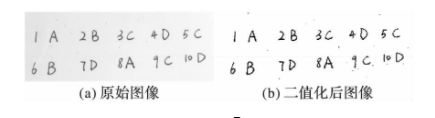
Figure 1 image binarization
1.3 contour denoising
After Gaussian filtering, the noise caused by the camera sensor can be removed or reduced, but the noise processing effect of the paper itself can not meet the requirements. In the process of practical application, uneven and irregular noise may appear in the background area except letters. Therefore, this paper uses the way of looking for the contour of connected domain, finds the contour of all connected domains, calculates their contour area, and sets an area threshold. The connected domain whose contour area is less than the threshold can be judged as noise and eliminated. After a large number of experiments, this paper sets to remove the pixels whose pixel area is less than 12. The specific contour extraction method is described in detail later. Fig. 2 is an image after contour denoising.
2 character segmentation
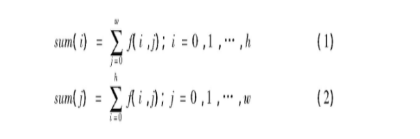
The projection feature of image is one of the important technologies in image processing. Generally, the image feature is analyzed by calculating the total number of pixels (black or white) at each position of X-axis or Y-axis, and drawing the corresponding projection curve. This technology is often used in image segmentation, character detection and extraction. Formulas (1) and (2) are the calculation formulas of horizontal projection and vertical projection respectively. Where h and w are the height and width of the binary image respectively; f(i, j) is the value 1 or 0 of the element in row i and column j of the image.
2.1 line segmentation
Line segmentation is to horizontally project the X-axis direction of the image to obtain the total number of white dots at each position in the X-axis direction. If the total number of white dots at a position is 0, it means that there is no handwriting trace at that position. Because people's common writing habit is to write line by line, and there is a certain distance between lines, we can know which positions have not been written through line segmentation, so we can roughly divide the handwritten area by line.
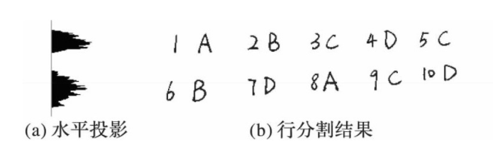
Figure 3 line segmentation process
2.2 column segmentation
Column segmentation is to vertically project the Y-axis direction of the image to obtain the total number of white points at each position in the Y-axis direction. If the total number of white points at a certain position is 0, it indicates that the position is the gap between letters. Through column segmentation, each letter can be easily extracted for subsequent recognition.
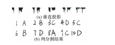
Figure 4 column segmentation process
2.3 minimum image segmentation
After row segmentation and column segmentation, the letters are basically divided into separate images, but the image size is often large and the proportion of letters in the whole image is small. In order to reduce the image processing time and facilitate the subsequent letter recognition, it is necessary to cut the segmented letter again to make the letters occupy the whole image as much as possible. The black border in Figure 5 is the image boundary.
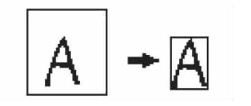
Fig. 5 Schematic diagram of minimum image
3 Classification and identification
For letters A~D, it is easy to find their contour features. Letters A and D contain a closed curve; The letter B contains 2 closed curves; The letter C contains 0 closed curves, so you can roughly divide the letters by extracting the number of closed curves of the letters, and then distinguish between a and D. After extracting the contour features, the shape features are extracted, and the final recognition results can be obtained by fusing the recognition results of the two features
3.1 contour feature extraction
Contour extraction is one of the common methods in image processing. Contour can be simply regarded as a curve connecting continuous points, with the same color or gray. Through the topological analysis of the binary image, the image is scanned, and different integer values are given to different contours, so as to determine the outer contour, inner contour and their hierarchical relationship. As shown in Fig. 6, there are two black contours, 1a is the outer boundary of the first black contour, 1b is the hole boundary of the first black contour, 2a is the outer boundary of the second black contour, and 2b is the hole boundary of the second black contour.
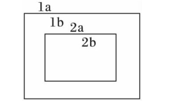
Figure 6 outline diagram
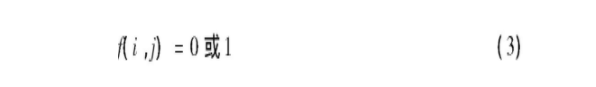
The specific operation is to scan the binary image first, judge the pixel value of the pixel point, and use equation (3) to represent the pixel value of the image. i is the number of rows of the image and j is the number of columns of the image.
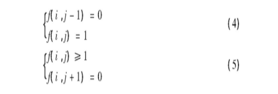
When the line is scanned to the outer boundary of the contour and the hole boundary, the scanning is terminated. Equation (4) is the outer boundary termination condition and equation (5) is the hole boundary termination condition. Take f(i, j) at the end of scanning as the starting point, mark the pixels on the boundary and give the boundary a value (such as 1). After each new boundary is found, add 1 to the value. In Fig. 6, there are two contours, the first contour is marked with 1 and the second contour is marked with 2. In this way, the contour detection is completed.
In this paper, by extracting the contour of the segmented handwritten English letters, A~D can be easily divided into three categories: C with the number of contours of 0; The number of contours is 1
A,D; There is B with the number of contours of 2.
Since the letters A and d have the same number of outlines, it is necessary to distinguish the two letters. By analyzing the contour characteristics of letters A and D, it can be found that for letters A and D of the same size, the contour area of letter A is smaller than that of letter D; For the letter A and letter D which are already the smallest images, through the statistical analysis of 182 handwritten English letter data, it is obtained that the proportion of the outline area of letter A in the image area is 0.075194884, and the proportion of the outline area of letter D in the image area is 0.321412. It can be seen that the proportion of the outline area of letter A in the size area is less than that of letter D. Therefore, in Wang recognition, it is only necessary to calculate the difference between the proportion of the outline area of the letter to be recognized and the proportion coefficient of the letter A and the proportion coefficient of the letter D respectively, and then compare them to distinguish a and D. Fig. 7 is a schematic diagram of the extracted contour area of letter A and letter D.
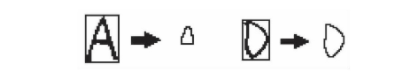
Figure 7 Schematic diagram of contour area extraction of letter A and letter D
3.2 shape feature extraction
By analyzing the shapes of English letters A~D, the shape characteristics of each letter can be found. The specific operations are as follows: fill the binary image obtained after preprocessing (as shown in Fig. 8(a)) to obtain Fig. 8(b). It can be seen that the shape of letter A is similar to a triangle; The shape of the letter B includes two convex parts and a concave part; The letter C also contains two convex parts and a concave part; The letter D has only one raised part. Then, the horizontal projection is performed on Fig. 8(b), and the pixel sum of each line of letters is displayed on the projection histogram (Fig. 8 ©), By analyzing the pixels and data of each letter, we can get that the data curve of letter a increases monotonically; The data curve of letter B contains two peaks and one trough; The data curve of letter C also contains two peaks and one trough; The data curve of the letter D contains a crest.
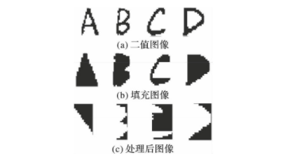
Figure 8 shape feature extraction process
After the data of each letter is obtained, the difference operation is carried out on the data curve. The peak point of the curve meets that the first derivative is 0 and the second derivative is negative; The trough point satisfies that the first derivative is 0 and the second derivative is positive; The monotonicity curve satisfies that the first derivative is not 0, so the letters can be divided into A, B, C and D. The algorithm flow is as follows: the data curve can be regarded as A one-dimensional vector as follows:

Where vi (i ∈ [1, 2,..., N]) represents the sum of white pixels on line i of the image. Calculate the first-order difference vector Diffv of V:

After obtaining the difference vector, carry out symbolic function operation, as shown in equation (8):
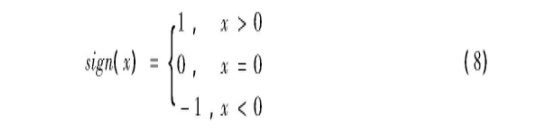
At this time, the change of each point can be obtained, but some points have the same value, but they are not peaks and troughs. Then conduct another first-order difference to obtain the peaks or troughs of the data curve.
3.3 special treatment
As it is inevitable to fill in the wrong answers in the exam, special treatment needs to be made for this situation. This paper designs a wrong answer marking method on the basis of letter recognition. For the wrong answer, you can draw two non repetitive slashes from left to right and two non repetitive slashes from right to left. As shown in Figure 9, the outline number of the wrong answer after marking will exceed the outline number of normal letters, so you can distinguish the wrong answer.
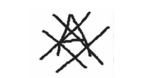
Figure 9 special case handling
2, Partial source code
function varargout = untitled(varargin)
% UNTITLED MATLAB code for untitled.fig
%      UNTITLED, by itself, creates a new UNTITLED or raises the existing
%      singleton*.
%
%      H = UNTITLED returns the handle to a new UNTITLED or the handle to
%      the existing singleton*.
%
%      UNTITLED('CALLBACK',hObject,eventData,handles,...) calls the local
%      function named CALLBACK in UNTITLED.M with the given input arguments.
%
%      UNTITLED('Property','Value',...) creates a new UNTITLED or raises the
%      existing singleton*.  Starting from the left, property value pairs are
%      applied to the GUI before untitled_OpeningFcn gets called.  An
%      unrecognized property name or invalid value makes property application
%      stop.  All inputs are passed to untitled_OpeningFcn via varargin.
%
%      *See GUI Options on GUIDE's Tools menu.  Choose "GUI allows only one
%      instance to run (singleton)".
%
% See also: GUIDE, GUIDATA, GUIHANDLES

% Edit the above text to modify the response to help untitled

% Last Modified by GUIDE v2.5 05-Jan-2022 19:52:04

% Begin initialization code - DO NOT EDIT
gui_Singleton = 1;
gui_State = struct('gui_Name',       mfilename, ...
                   'gui_Singleton',  gui_Singleton, ...
                   'gui_OpeningFcn', @untitled_OpeningFcn, ...
                   'gui_OutputFcn',  @untitled_OutputFcn, ...
                   'gui_LayoutFcn',  [] , ...
                   'gui_Callback',   []);
if nargin && ischar(varargin{1})
    gui_State.gui_Callback = str2func(varargin{1});
end

if nargout
    [varargout{1:nargout}] = gui_mainfcn(gui_State, varargin{:});
else
    gui_mainfcn(gui_State, varargin{:});
end
% End initialization code - DO NOT EDIT


% --- Executes just before untitled is made visible.
function untitled_OpeningFcn(hObject, eventdata, handles, varargin)
% This function has no output args, see OutputFcn.
% hObject    handle to figure
% eventdata  reserved - to be defined in a future version of MATLAB
% handles    structure with handles and user data (see GUIDATA)
% varargin   command line arguments to untitled (see VARARGIN)

% Choose default command line output for untitled
handles.output = hObject;

% Update handles structure
guidata(hObject, handles);

% UIWAIT makes untitled wait for user response (see UIRESUME)
% uiwait(handles.figure1);


% --- Outputs from this function are returned to the command line.
function varargout = untitled_OutputFcn(hObject, eventdata, handles)
% varargout  cell array for returning output args (see VARARGOUT);
% hObject    handle to figure
% eventdata  reserved - to be defined in a future version of MATLAB
% handles    structure with handles and user data (see GUIDATA)

% Get default command line output from handles structure
varargout{1} = handles.output;


% --- Executes on button press in pushbutton1.
function pushbutton1_Callback(hObject, eventdata, handles)
% hObject    handle to pushbutton1 (see GCBO)
% eventdata  reserved - to be defined in a future version of MATLAB
% handles    structure with handles and user data (see GUIDATA)
[filename, pathname] = uigetfile({'*.jpg;*.tif;*.png;*.gif;*.bmp','All Image Files';...
    '*.*','All Files' },'Load Image ',...
    fullfile(pwd, 'images'));

if isequal(filename, 0) || isequal(pathname, 0)
    return;
end

% [FileName,Pathname]=uigetfile('*.jpg;*.jpeg;*.bmp;*.png;*.gif');
F_P=fullfile(pathname,filename);
img=imread(F_P);
handles.path=F_P;
handles.img=img;

axes(handles.axes1);imshow(img);
guidata(hObject,handles);


% --- Executes on button press in pushbutton2.
function pushbutton2_Callback(hObject, eventdata, handles)
% hObject    handle to pushbutton2 (see GCBO)
% eventdata  reserved - to be defined in a future version of MATLAB
% handles    structure with handles and user data (see GUIDATA)
[out1,out2]=main_(handles.img);
axes(handles.axes3);imshow(out2);
set(handles.edit1,'string',out1);


function edit1_Callback(hObject, eventdata, handles)
% hObject    handle to edit1 (see GCBO)
% eventdata  reserved - to be defined in a future version of MATLAB
% handles    structure with handles and user data (see GUIDATA)

% Hints: get(hObject,'String') returns contents of edit1 as text
%        str2double(get(hObject,'String')) returns contents of edit1 as a double


% --- Executes during object creation, after setting all properties.
function edit1_CreateFcn(hObject, eventdata, handles)
% hObject    handle to edit1 (see GCBO)
% eventdata  reserved - to be defined in a future version of MATLAB
% handles    empty - handles not created until after all CreateFcns called

% Hint: edit controls usually have a white background on Windows.
%       See ISPC and COMPUTER.
if ispc && isequal(get(hObject,'BackgroundColor'), get(0,'defaultUicontrolBackgroundColor'))
    set(hObject,'BackgroundColor','white');
end
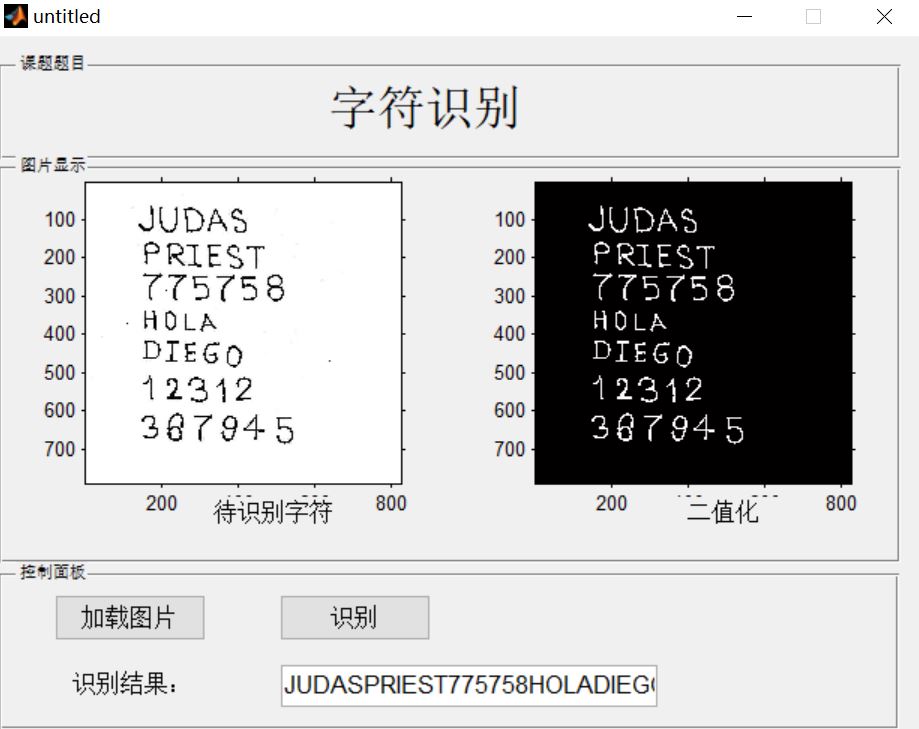
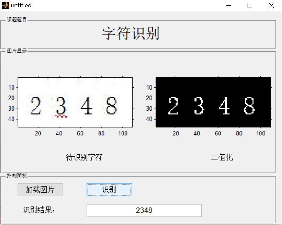
3, Operation results
4, matlab version and references
1 matlab version
2014a
2 references
[1] Cai Limei MATLAB image processing -- theory, algorithm and example analysis [M] Tsinghua University Press, 2020
[2] Yang Dan, Zhao Haibin, long Zhe Detailed explanation of MATLAB image processing example [M] Tsinghua University Press, 2013
[3] Zhou pin MATLAB image processing and graphical user interface design [M] Tsinghua University Press, 2013
[4] Liu Chenglong Proficient in MATLAB image processing [M] Tsinghua University Press, 2015