I. Introduction
Mathematical morphology is a subject based on set theory. It is a powerful tool for geometric morphology analysis and description. The history of mathematical morphology can be traced back to the 19th century. In 1964, Matheron and Serra of France introduced mathematical morphology into the field of image processing based on the research results of integral geometry, and developed an image processing system based on mathematical morphology. The monograph Image Analysis and Mathematical Morphology published in 1982 is an important milestone in the development of mathematical morphology, indicating that mathematical morphology tends to be complete in theory and deepening in application. Mathematical morphology is booming. Because of its fast parallel and easy hardware implementation, it has attracted extensive attention. At present, mathematical morphology has been widely used in computer vision, signal processing and image analysis, pattern recognition, calculation method and data processing.
Mathematical morphology can be used to solve image processing problems such as noise suppression, feature extraction, edge detection, image segmentation, shape recognition, texture analysis, image restoration and reconstruction, image compression and so on. This paper will mainly summarize the basic theory of mathematical morphology and its application in image processing.
II. Definition and classification of mathematical morphology
Mathematical morphology is a mathematical tool for image analysis based on morphological structure elements. Its basic idea is to measure and extract the corresponding shape in the image with the structural elements with a certain shape, so as to achieve the purpose of image analysis and recognition. The application of mathematical morphology can simplify image data, maintain their basic shape features, and remove irrelevant structures. There are four basic operations of mathematical morphology: expansion, corrosion, opening and closing. They have their own characteristics in binary image and gray image. Based on these basic operations, various practical algorithms of mathematical morphology can also be deduced and combined.
(1) Binary morphology
The mathematical transformation is a kind of morphological set processing. The essence of its morphological operator is to express the interaction between the set of objects or shapes and structural elements. The shape of structural elements determines the shape information of the signal extracted by this operation. Morphological image processing is to move a structural element in the image, and then intersect and merge the structural element with the following binary image.
The basic morphological operations are corrosion and expansion.
In morphology, structural element is the most important and basic concept. The role of structural elements in morphological transformation is equivalent to the "filter window" in signal processing. B (x) is used to represent structural elements. For each point X in workspace E, corrosion and expansion are defined as:
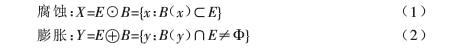
The result of etching e with B (x) is the set composed of all points of E after translating the structural element B. The result of expanding e with B (x) is the set of points that make the intersection of B and e non empty after translating the structural element B. The process of corrosion before expansion is called open operation. It has the function of eliminating small objects, separating objects from thin objects and smoothing the boundary of larger objects. The process of expansion before corrosion is called closed operation. It has the function of filling the small cavity in the object, connecting the adjacent object and smoothing the boundary.
It can be seen that binary morphological expansion and corrosion can be transformed into set logic operation. The algorithm is simple, suitable for parallel processing, and easy to implement in hardware. It is suitable for image segmentation, thinning, skeleton extraction, edge extraction and shape analysis of binary images. However, in different applications, the selection of structural elements and their corresponding processing algorithms are different. Different structural elements and different processing algorithms need to be designed for different target images. Whether the size and shape of structural elements are appropriate or not will directly affect the morphological operation results of the image. Therefore, many scholars put forward a series of improved algorithms combined with their own application practice. For example, the edge detection algorithm using multi-directional morphological structural elements proposed by Liang Yong not only has good edge positioning ability, but also has good noise smoothing ability. Xu Chao proposed a design method combining the construction of quasi circular structural elements with the shortest line segment structural elements or the generation of quasi circular structural elements with sequence structural elements. For the extraction of skeleton, it can greatly reduce the amount of calculation of morphological operation, meet the compatibility of scale, translation and rotation at the same time, and is suitable for the analysis and description of shape.
(2) Gray mathematical morphology
Binary mathematical morphology can be easily extended to gray image space. But the operation object of gray mathematical morphology is not a set, but an image function. Let f (x, y) be the input image and b (x, y) be the structural element. The expansion and corrosion operations of the input image y with the structural element b are defined as: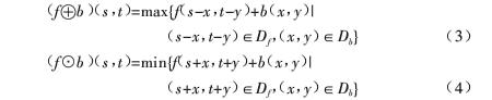
There are two kinds of effects on the expansion (or corrosion) operation of gray image:
(1) If the values of structural elements are positive, the output image will be brighter (or darker) than the input image;
(2) According to the gray value of dark (or bright) details in the input image and the relationship between their shapes and structural elements, they are either reduced or eliminated in the operation. The definitions of opening and closing operations in gray mathematical morphology are consistent with those in binary mathematical morphology. The definition of opening and closing f with b is: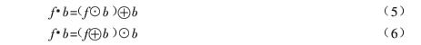
(3) Fuzzy mathematical morphology
Applying fuzzy set theory to mathematical morphology forms fuzzy morphology. The definition of fuzzy operator is different, and the corresponding definition of fuzzy morphological operation is also different. Here, Shinba's definition method is selected. Fuzziness is determined by the adaptability of structural elements to the original image. The corrosion and expansion operation of fuzzy image with fuzzy structural elements supported by boundaries is defined as follows according to their membership function:
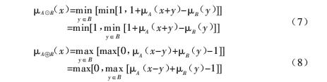
Where x,y ∈ Z2 represents spatial coordinates, ua and ub represent the membership functions of image and structural elements respectively. According to the results of equations (7) and (8), the membership functions after fuzzy morphological corrosion expansion operation fall within the interval of [0,1]. Fuzzy morphology is the extension of traditional mathematical morphology from binary logic to fuzzy logic. It has similar calculation results and algebraic characteristics with traditional mathematical morphology. Fuzzy morphology focuses on the shape characteristics and shape transformation of n-dimensional space target objects. It is mainly used in the field of image processing, such as fuzzy enhancement, fuzzy edge detection, fuzzy segmentation and so on.
function varargout = appletest(varargin)
% APPLETEST MATLAB code for appletest.fig
% APPLETEST, by itself, creates a new APPLETEST or raises the existing
% singleton*.
%
% H = APPLETEST returns the handle to a new APPLETEST or the handle to
% the existing singleton*.
%
% APPLETEST('CALLBACK',hObject,eventData,handles,...) calls the local
% function named CALLBACK in APPLETEST.M with the given input arguments.
%
% APPLETEST('Property','Value',...) creates a new APPLETEST or raises the
% existing singleton*. Starting from the left, property value pairs are
% applied to the GUI before appletest_OpeningFcn gets called. An
% unrecognized property name or invalid value makes property application
% stop. All inputs are passed to appletest_OpeningFcn via varargin.
%
% *See GUI Options on GUIDE's Tools menu. Choose "GUI allows only one
% instance to run (singleton)".
%
% See also: GUIDE, GUIDATA, GUIHANDLES
% Edit the above text to modify the response to help appletest
% Last Modified by GUIDE v2.5 17-May-2021 23:40:39
% Begin initialization code - DO NOT EDIT
gui_Singleton = 1;
gui_State = struct('gui_Name', mfilename, ...
'gui_Singleton', gui_Singleton, ...
'gui_OpeningFcn', @appletest_OpeningFcn, ...
'gui_OutputFcn', @appletest_OutputFcn, ...
'gui_LayoutFcn', [] , ...
'gui_Callback', []);
if nargin && ischar(varargin{1})
gui_State.gui_Callback = str2func(varargin{1});
end
if nargout
[varargout{1:nargout}] = gui_mainfcn(gui_State, varargin{:});
else
gui_mainfcn(gui_State, varargin{:});
end
% End initialization code - DO NOT EDIT
% --- Executes just before appletest is made visible.
function appletest_OpeningFcn(hObject, eventdata, handles, varargin)
% This function has no output args, see OutputFcn.
% hObject handle to figure
% eventdata reserved - to be defined in a future version of MATLAB
% handles structure with handles and user data (see GUIDATA)
% varargin command line arguments to appletest (see VARARGIN)
% Choose default command line output for appletest
handles.output = hObject;
% Update handles structure
guidata(hObject, handles);
% UIWAIT makes appletest wait for user response (see UIRESUME)
% uiwait(handles.figure1);
% --- Outputs from this function are returned to the command line.
function varargout = appletest_OutputFcn(hObject, eventdata, handles)
% varargout cell array for returning output args (see VARARGOUT);
% hObject handle to figure
% eventdata reserved - to be defined in a future version of MATLAB
% handles structure with handles and user data (see GUIDATA)
% Get default command line output from handles structure
varargout{1} = handles.output;
% --- Executes on button press in pushbutton1.
function pushbutton1_Callback(hObject, eventdata, handles)
% hObject handle to pushbutton1 (see GCBO)
% eventdata reserved - to be defined in a future version of MATLAB
% handles structure with handles and user data (see GUIDATA)
[filename,pathname]=uigetfile({'*.*';'*.bmp';'*.jpg';'*.tif';'*.jpg'},'Select image');
image=[pathname,filename];%Synthetic path+file name
im=imread(image);%Read image
im=im2double(im);
axes(handles.axes1);
imshow(im);%In coordinates axes1 Display original image
title('original image ');
handles.X1=im;
guidata(hObject,handles);
% --- Executes on selection change in popupmenu1.
function popupmenu1_Callback(hObject, eventdata, handles)
% hObject handle to popupmenu1 (see GCBO)
% eventdata reserved - to be defined in a future version of MATLAB
% handles structure with handles and user data (see GUIDATA)
% Hints: contents = cellstr(get(hObject,'String')) returns popupmenu1 contents as cell array
% contents{get(hObject,'Value')} returns selected item from popupmenu1
Val=get(hObject,'Value')
strl=get(hObject,'string')
switch strl{Val};
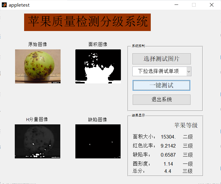
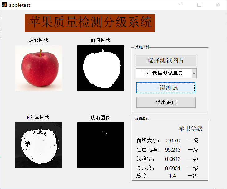
case ' the measure of area'
x1=handles.X1;
w=rgb2gray(x1);
L=medfilt2(w);
level=graythresh(L);
bw=im2bw(L,level);
bw=imfill(~bw,'holes');
axes(handles.axes2);
imshow(bw);
title('Area image');
strNC=[num2str(bwarea(bw))];
set(handles.text9,'string',strNC);
strNC1=('Primary fruit');
strNC2=('Secondary fruit');
strNC3=('Tertiary fruit');
if bwarea(bw)>30000
Complete code or simulation consultation add QQ1575304183