1, Introduction
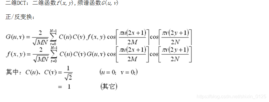
1 DCT algorithm:
The full name of DCT transform is discrete cosine transform. Discrete cosine transform is equivalent to a discrete Fourier transform whose length is about twice its length. This discrete Fourier transform is performed on a real even function. Through the study of digital signal processing, we know that the spectrum obtained by the Fourier transform of real function is mostly complex, while the Fourier transform result of even function is real function. On this basis, making the signal function become an even function and removing the imaginary part of the spectrum function is one of the characteristics of cosine transform. It can convert a set of light intensity data into frequency data in order to know the change of intensity. If we modify the high-frequency data and then turn back to the original form of data, it is obviously different from the original data, but it is not easy for human eyes to recognize it. During compression, the original image data is divided into 8 * 8 data unit matrix, such as the first matrix of brightness value.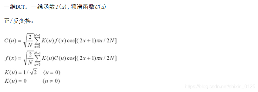
2. Engineering background of DCT:
The spectrum line of the video signal is in the range of 0-6MHz, and most of the spectrum lines contained in a video image are low-frequency spectrum lines. Only the video signal at the edge of the image with a low proportion of the image area contains high-frequency spectrum lines. Therefore, in the digital processing of video signal, the number of bits can be allocated according to the spectrum factors: more bits can be allocated to the low-frequency spectrum area with large amount of information, and less bits can be allocated to the high-frequency spectrum area with low amount of information, while the image quality has no perceptible damage, so as to achieve the purpose of code rate compression. However, all this needs to be in the case of low entropy value in order to achieve effective coding. Whether a string of data can be encoded effectively depends on the probability of each data. The large difference in the probability of each data indicates that the entropy is low and the string of data can be encoded efficiently. On the contrary, if the probability difference is small and the entropy value is high, efficient coding cannot be carried out. The digitization of video signal is converted from video level by A/D converter under the specified sampling frequency. The video signal amplitude of each pixel changes periodically with the time of each layer. The sum of the average information of each pixel is the total average information, that is, entropy. Because each video level has almost equal probability, the entropy of video signal is very high. Entropy is a parameter that defines the bit rate compression rate. The compression rate of video image depends on the entropy of video signal. In most cases, the video signal is high entropy. In order to encode efficiently, it is necessary to change the high entropy into low entropy. How to become low entropy? Therefore, it is necessary to analyze the characteristics of video spectrum. In most cases, the amplitude of video spectrum decreases with the increase of frequency. The low-frequency spectrum obtains the level from 0 to the highest with almost equal probability. In contrast, high-frequency spectrum usually obtains low-level and rare high-level. Obviously, the low-frequency spectrum has high entropy and the high-frequency spectrum has low entropy. Accordingly, the low-frequency component and high-frequency component of the video can be processed respectively to obtain the high-frequency compression value.
Since Ahmed and Rao gave the definition of discrete cosine transform (DCT) in 1974, discrete cosine transform (DCT) and improved discrete cosine transform (MDCT) have become important tools and technologies widely used in signal processing and image processing, especially for image compression and speech compression coding and decoding. They have always been the research hotspot of international academia and high-tech industry. Many current image and video coding standards (such as the second part of MPEG-1, MEPG-2 and MEPG-4) require the implementation of integer 8 × 8, while MDCT and IMDCT are mainly used in the coding and decoding of audio signals (such as MPEG-1, MEPG-2, AC -] and other standard audio coding parts). This kind of transformation is particularly important because it is widely used. Especially, the research of fast algorithm under specific application conditions is very helpful to improve the performance of the whole system.
As can be seen from the above references, rate compression is based on two algorithms: transform coding and entropy coding. The former is used to reduce entropy, and the latter turns the data into an effective coding method that can reduce the number of bits. In MPEG standard, DCT is used for transform coding. Although the transform process itself does not produce rate compression, the transformed frequency coefficient is very conducive to rate compression. In fact, the whole process of compressing digital video signal is divided into four main processes: block sampling, DCT, quantization and coding - first, divide the original image into n (horizontal) in the time domain × N (vertical) sampling block, 4 as required × 4,4 × 8,8 × 8,8 × 16,16 × 16 and other blocks. These sampled pixel blocks represent the gray value of each pixel of the original image frame, which ranges from 139 to 163, and are sent to the DCT encoder in order to convert the sampling block from time domain to DCT coefficient block in frequency domain. The conversion of DCT system is carried out in each sampling block. Each sampling in these blocks is the digitized value, which represents the video signal amplitude value of the corresponding pixel in a field
3 implementation of discrete cosine transform:
There are many methods to realize DCT, and the most direct one is to calculate according to the definition of DCT. Taking two-dimensional 8xSDCT as an example, 4096 times of multiplication and 3584 times of addition are required. The implementation of this algorithm requires a huge amount of calculation and has no practical value. In application, we need to find fast and accurate algorithms. The commonly used method is to take advantage of the separability of DCT. Similarly, taking two-dimensional 8xSDCT as an example, 64xS times of multiplication and 56xS times of addition are required for eight rows of one-dimensional DCT, and then 64xS times of multiplication and 56xS times of addition are required for eight columns of one-dimensional DCT. A total of 64x8xZ=1024 times of multiplication and 56x8xZ=896 times of addition are required, which greatly reduces the amount of calculation.
In addition, DCT has many open fast algorithms. Fast algorithm mainly reduces the operation time by reducing the number of operations, which is very effective for designing fast hardware system. The fast algorithm of two-dimensional DCT generally adopts row column separation DCT algorithm, that is, it is transformed into two one-dimensional transformations, which are connected by transpose matrix. The most classic and commonly used fast algorithms are AAN algorithm proposed by Arai et al. In 1988 and LLM algorithm proposed by Loeffier et al. In 1989. However, because the row column separation DCT algorithm can reuse the one-dimensional transformation structure, it has more advantages than the two-dimensional direct calculation algorithm in practical implementation, especially in hardware.
2, Source code
function varargout = imDCT(varargin)
% IMDCT M-file for imDCT.fig
% IMDCT, by itself, creates a new IMDCT or raises the existing
% singleton*.
%
% H = IMDCT returns the handle to a new IMDCT or the handle to
% the existing singleton*.
%
% IMDCT('CALLBACK',hObject,eventData,handles,...) calls the local
% function named CALLBACK in IMDCT.M with the given input arguments.
%
% IMDCT('Property','Value',...) creates a new IMDCT or raises the
% existing singleton*. Starting from the left, property value pairs are
% applied to the GUI before imDCT_OpeningFcn gets called. An
% unrecognized property name or invalid value makes property application
% stop. All inputs are passed to imDCT_OpeningFcn via varargin.
%
% *See GUI Options on GUIDE's Tools menu. Choose "GUI allows only one
% instance to run (singleton)".
%
% See also: GUIDE, GUIDATA, GUIHANDLES
% Edit the above text to modify the response to help imDCT
% Last Modified by GUIDE v2.5 07-Dec-2009 19:54:09
% Begin initialization code - DO NOT EDIT
gui_Singleton = 1;
gui_State = struct('gui_Name', mfilename, ...
'gui_Singleton', gui_Singleton, ...
'gui_OpeningFcn', @imDCT_OpeningFcn, ...
'gui_OutputFcn', @imDCT_OutputFcn, ...
'gui_LayoutFcn', [] , ...
'gui_Callback', []);
if nargin && ischar(varargin{1})
gui_State.gui_Callback = str2func(varargin{1});
end
if nargout
[varargout{1:nargout}] = gui_mainfcn(gui_State, varargin{:});
else
gui_mainfcn(gui_State, varargin{:});
end
% End initialization code - DO NOT EDIT
% --- Executes just before imDCT is made visible.
function imDCT_OpeningFcn(hObject, eventdata, handles, varargin)
% This function has no output args, see OutputFcn.
% hObject handle to figure
% eventdata reserved - to be defined in a future version of MATLAB
% handles structure with handles and user data (see GUIDATA)
% varargin command line arguments to imDCT (see VARARGIN)
% Choose default command line output for imDCT
handles.output = hObject;
% Update handles structure
guidata(hObject, handles);
% UIWAIT makes imDCT wait for user response (see UIRESUME)
% uiwait(handles.figure1);
% --- Outputs from this function are returned to the command line.
function varargout = imDCT_OutputFcn(hObject, eventdata, handles)
% varargout cell array for returning output args (see VARARGOUT);
% hObject handle to figure
% eventdata reserved - to be defined in a future version of MATLAB
% handles structure with handles and user data (see GUIDATA)
% Get default command line output from handles structure
varargout{1} = handles.output;
function edit1_Callback(hObject, eventdata, handles)
% hObject handle to edit1 (see GCBO)
% eventdata reserved - to be defined in a future version of MATLAB
% handles structure with handles and user data (see GUIDATA)
% Hints: get(hObject,'String') returns contents of edit1 as text
% str2double(get(hObject,'String')) returns contents of edit1 as a double
% --- Executes during object creation, after setting all properties.
function edit1_CreateFcn(hObject, eventdata, handles)
% hObject handle to edit1 (see GCBO)
% eventdata reserved - to be defined in a future version of MATLAB
% handles empty - handles not created until after all CreateFcns called
% Hint: edit controls usually have a white background on Windows.
% See ISPC and COMPUTER.
if ispc && isequal(get(hObject,'BackgroundColor'), get(0,'defaultUicontrolBackgroundColor'))
set(hObject,'BackgroundColor','white');
end
function edit2_Callback(hObject, eventdata, handles)
% hObject handle to edit2 (see GCBO)
% eventdata reserved - to be defined in a future version of MATLAB
% handles structure with handles and user data (see GUIDATA)
% Hints: get(hObject,'String') returns contents of edit2 as text
% str2double(get(hObject,'String')) returns contents of edit2 as a double
% --- Executes during object creation, after setting all properties.
function edit2_CreateFcn(hObject, eventdata, handles)
% hObject handle to edit2 (see GCBO)
% eventdata reserved - to be defined in a future version of MATLAB
% handles empty - handles not created until after all CreateFcns called
% Hint: edit controls usually have a white background on Windows.
% See ISPC and COMPUTER.
if ispc && isequal(get(hObject,'BackgroundColor'), get(0,'defaultUicontrolBackgroundColor'))
set(hObject,'BackgroundColor','white');
end
% --- Executes on button press in pushbutton1.
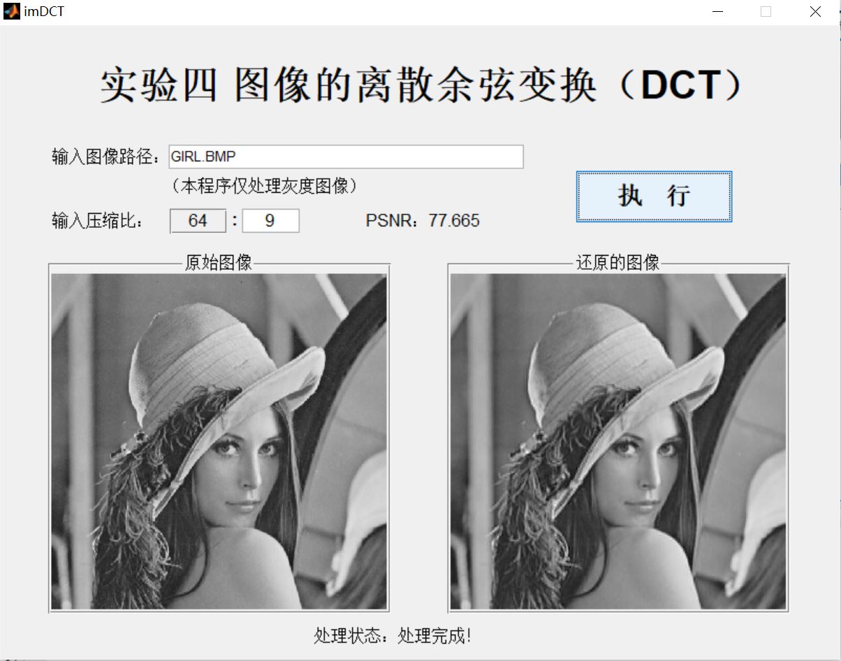
function pushbutton1_Callback(hObject, eventdata, handles)
ImgPath=get(handles.edit1,'String');
CompressRate=uint8(fix(str2num(get(handles.edit2,'String'))));
if CompressRate>64
CompressRate=64;
end
if CompressRate<1
CompressRate=1;
end
set(handles.edit2,'String',num2str(CompressRate));
img=imread(ImgPath);
axes(handles.axes1);
imshow(img);
set(handles.text7,'Visible','off');
set(handles.text7,'String','Processing status: Processing...');
set(handles.text7,'Visible','on');
pause(0.1);
Block=ceil(size(img)/8);
ImgDCT=zeros(Block*8);
ImgRestoreTemp=zeros(Block*8);
ImgRestore=zeros(size(img));
ImgBlock=zeros(8);
DCTBlock=zeros(8);
vector=zeros(1,64);
for ii=1:Block(1)
for jj=1:Block(2)
ImgBlock(:,:)=zeros(8);
if ii==Block(1)
if jj==Block(2)
ImgBlock(1:size(img,1)-(ii-1)*8,1:size(img,2)-(jj-1)*8)=img((ii-1)*8+1:size(img,1),(jj-1)*8+1:size(img,2));
else
ImgBlock(1:size(img,1)-(ii-1)*8,:)=img((ii-1)*8+1:size(img,1),(jj-1)*8+1:jj*8);
end
else
if jj==Block(2)
ImgBlock(:,1:size(img,2)-(jj-1)*8)=img((ii-1)*8+1:ii*8,(jj-1)*8+1:size(img,2));
else
ImgBlock(:,:)=img((ii-1)*8+1:ii*8,(jj-1)*8+1:jj*8);
end
end
DCTBlock(:,:)=dct2(ImgBlock(:,:));
if CompressRate~=64
vector(1:64)=m2v(DCTBlock(:,:));
vector(CompressRate+1:64)=0;
DCTBlock(:,:)=v2m(vector(1:64));
end
ImgDCT((ii-1)*8+1:ii*8,(jj-1)*8+1:jj*8)=DCTBlock(:,:);
end
end
3, Operation results
4, Remarks
Complete code or write on behalf of QQ1575304183