1. Tasks
A four digit simple calculator is designed. The number keys are input by the matrix keyboard and the display is output by the four digit nixie tube. The four operations of +, -, *, / can be realized correctly (regardless of the operation of decimals).
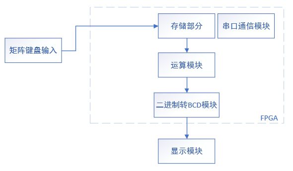
2. System block diagram
It is mainly composed of five modules, namely matrix keyboard scanning module, nixie tube display module, binary to BCD module and operation module. The block diagram is shown in the figure below:
3. Modular design
3.1 top level module preparation
As the entrance of the program, the top-level module calls each module to realize the functions of each module. The source code is as follows:
module cal_top(

	Clk,Rst_n,key_c,key_r,dig_sel,dig_data

	);

// input
	input Clk;						//50MHz
	input Rst_n;					//Reset low level active
	input [3:0]key_r;				//Matrix keyboard row

// output
	output wire [3:0]key_c;			//Matrix keyboard column
	output wire[7:0]dig_data;		//Nixie tube segment code
	output wire[3:0]dig_sel;		//4-digit nixie tube bit selection

	wire key_in;
	wire [3:0]key_out;
	wire key_flag;					//Press the key to press the flag bit
	wire key_state;					//Key state

	reg [4:0]key_num;				//Key value pressed by the key

	reg [13:0]num_a;				//Operand a
	reg [13:0]num_b;				//Operand b

	reg dis_flag;
	reg [3:0]opera_flag;
	wire [13:0]out_a;
	wire [13:0]out_b;
	wire dis_flago;
	wire [3:0]opera_flago;
	wire out_flagd;

	reg [13:0]num_sel;
	wire [3:0]data_q;			//Thousand bit
	wire [3:0]data_b;			//Hundredth
	wire [3:0]data_s;			//Ten
	wire [3:0]data_g;			//Bit

	reg en;
	wire [13:0]out_num;
	wire num_flag;

	key_filter my_key_filter(
			.Clk(Clk),
			.Rst_n(Rst_n),
			.key_in(key_in),
			.key_flag(key_flag),
			.key_state(key_state)
			);
	key_array my_array(
			.Clk(Clk),
			.Rst_n(Rst_n),
			.key_c(key_c),
			.key_out(key_out),
			.key_r(key_r),
			.key_in(key_in)
			);

	dig_dynamic my_dig_dynamic(
				.Clk(Clk),
				.Rst_n(Rst_n),
				.En(1'b1),
				.disp_data({data_q[3:0],data_b[3:0],data_s[3:0],data_g[3:0]}),
				.dig_sel(dig_sel),
				.dig_data(dig_data)
				);

	bcd_d my_bcd_d(
			.binary(num_sel),
			.g(data_g),
			.s(data_s),
			.b(data_b),
			.q(data_q)
		);

	add  my_add(
			.num_a(num_sel),
			.en(en),
			.key_num(key_num),
			.out_a(out_num),
			.num_flag(num_flag)
		);

	opera my_opera(
			.num_a(num_a),
			.num_b(num_b),
			.en(en),
			.dis_flag(dis_flag),
			.opera_flag(opera_flag),
			.key_num(key_num),
			.out_a(out_a),
			.out_b(out_b),
			.dis_flago(dis_flago),
			.opera_flago(opera_flago),
			.out_flagd(out_flagd)
		);

	/********Number of choices******/
	always@(posedge Clk or negedge Rst_n)
	if(!Rst_n) begin
			num_a <= 14'd0;
			num_b <= 14'd0;
			dis_flag <= 1'b0;
	end
	else if(out_flagd == 1'b1) begin
			num_a <= out_a;
			num_b <= out_b;
			dis_flag <= dis_flago;
			opera_flag <= opera_flago;
	end
	else if(dis_flag == 1'b0) begin
			num_sel <= num_a;
			if(num_flag == 1'b1)
					num_a <= out_num;

			else
					num_a <= num_a;
	end
	else if(dis_flag == 1'b1) begin
			num_sel <= num_b;
			if(num_flag == 1'b1)
					num_b <= out_num;
			else
					num_b <= num_b;
	end

	/*************Operand en************/
	always@(posedge Clk or negedge Rst_n)
	if(!Rst_n)
		en <= 1'b0;
	else if(key_flag && (!key_state)) begin
			key_num <= key_out;
			en <= 1'b1;
		end
		else
			en <= 1'b0;
endmodule
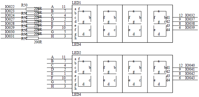
3.2 nixie tube dynamic display module
The nixie tube selected here is the common Yin nixie tube. Although there are 8 digits in the schematic diagram, only four digit nixie tubes are actually used. If necessary, you can change it to the common Yang nixie tube or increase the number of digits displayed by the nixie tube. Then, the nixie tube is directly connected to the IO without passing through other chips. Some other development boards may pass through the 138 decoder. If you download it, please modify it yourself. The schematic diagram is as follows:
module dig_dynamic(
	Clk,
	Rst_n,
	En,
	disp_data,
	dig_sel,
	dig_data
	);

	// input
	input		Clk;//Clock, 50MHz
	input		Rst_n;//Asynchronous reset signal, active at low level
	input		En; //Enable end: the high level is effective. When it is effective, the nixie tube displays normally, and it is not
						//All nixie tubes are off when
	input	[15:0]disp_data;//16 bit wide data to be displayed

	// output
	output	[3:0]dig_sel;   //Bit selection drive port of nixie tube
	output	[7:0]dig_data;//Segment selection drive port of nixie tube

	reg		[7:0]dig_data;

	reg		[14:0]Cnt;			//Frequency division counter
	reg		Clk_1k;				//1kHz sweep signal
	reg		[3:0]dig_sel_r;	//Temporary register for bit select data
	reg		[3:0]dig_data_temp;//Temporary register of data to be displayed

	//Scan cycle counter, return to zero after counting to 25000, and control to generate 1KHz sweep signal
	always@(posedge Clk or negedge Rst_n)
	if(!Rst_n)
		Cnt <= 15'h0;
	else if(En) begin
		if(Cnt == 15'd25000)
			Cnt <= 15'h0;
		else
			Cnt <= Cnt + 15'h1;
	end
	else
		Cnt <= Cnt;

	always@(posedge Clk or negedge Rst_n)
	if(!Rst_n)
		Clk_1k <= 1'h0;
	else if(Cnt == 15'd25000)
		Clk_1k <= ~Clk_1k;
	else
		Clk_1k <= Clk_1k;

	//Generate a constantly changing bit selection signal with an update frequency of 1KHz
	always@(posedge Clk_1k or negedge Rst_n)
	if(!Rst_n)
		dig_sel_r <= 4'b1110;
	else if(En)
		dig_sel_r <= {dig_sel_r[2:0],dig_sel_r[3]};
	else
		dig_sel_r <= dig_sel_r;

	//When enabled, the bit selection data is output normally. When not enabled, all 0 is output, that is, all nixie tubes are off
	assign	dig_sel = (En)?dig_sel_r:4'b0000;

	always@(*)
		case(dig_sel_r)
			4'b1110:dig_data_temp <= disp_data[3:0];		//Lowest digital tube
			4'b1101:dig_data_temp <= disp_data[7:4];
			4'b1011:dig_data_temp <= disp_data[11:8];
			4'b0111:dig_data_temp <= disp_data[15:12];
			default:dig_data_temp <= 4'b0000;
		endcase

	// Common cathode nixie tube
	always@(*)
		case(dig_data_temp)
			0: dig_data <= 8'h3F;		// 0
			1: dig_data <= 8'h06;
			2: dig_data <= 8'h5B;
			3: dig_data <= 8'h4F;
			4: dig_data <= 8'h66;
			5: dig_data <= 8'h6D;
			6: dig_data <= 8'h7D;
			7: dig_data <= 8'h07;
			8: dig_data <= 8'h7F;
			9: dig_data <= 8'h6F;
			10: dig_data <= 8'h77;
			11: dig_data <= 8'h7C;
			12: dig_data <= 8'h39;
			13: dig_data <= 8'h5E;
			14: dig_data <= 8'h79;
			15: dig_data <= 8'h71;
			default:;
		endcase

endmodule
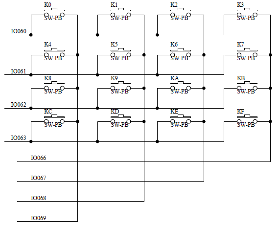
3.3 matrix keyboard scanning
The matrix keyboard is a 4 * 4 determinant keyboard; The scanning principle of matrix keyboard is to let four horizontal rows or four vertical columns output high level first, and the other four are input mode. If scanning to high level, it means that the key is pressed in this row or column, then switch input and output, scan the other four to obtain other coordinates, so as to determine the position of the key. The schematic diagram is shown in the following figure:
/********************************************************************
*					Matrix keyboard scanning
*	Function: use scanning method to detect matrix keyboard
*	Author: Ray
*	Starting time: April 24, 2021
*	Completion time: May 26, 2021
********************************************************************/
module key_array(

	Clk,Rst_n,key_r,key_c,key_out,key_in

	);
	input Clk;
	input Rst_n;
	input [3:0]key_r; 			//that 's ok

	output reg [3:0]key_c;		//column
	output reg [3:0]key_out;
	output reg key_in;


	always@(posedge Clk or negedge Rst_n)
	if(!Rst_n)
		key_c <= 4'b1110;
	else if (key_r == 4'b1111) begin
		if (key_c == 4'b0111)
			key_c <= 4'b1110;
		else begin
			key_c <= {key_c[2:0],key_c[3]};

		end
	end


	always@(posedge Clk or negedge Rst_n)
	if(!Rst_n)
		key_out <= 4'h6;
	else if (key_r == 4'b1111)
		key_in<=1'b1;
	else
		case(key_c)
			4'b1110 :
				case(key_r)
					4'b1110 : 	begin
									key_out <= 4'h1;
									key_in <= key_r[0];
									end

					4'b1101 : 	begin
									key_out <= 4'h4;
									key_in <= key_r[1];
									end

					4'b1011 : 	begin
									key_out <= 4'h7;
									key_in <= key_r[2];
									end

					4'b0111 : 	begin
									key_out <= 4'ha;
									key_in <= key_r[3];
									end
				endcase
			4'b1101 :
				case(key_r)
					4'b1110 : 	begin
									key_out <= 4'h2;
									key_in <= key_r[0];
									end

					4'b1101 : 	begin
									key_out <= 4'h5;
									key_in <= key_r[1];
									end

					4'b1011 : 	begin
									key_out <= 4'h8;
									key_in <= key_r[2];
									end

					4'b0111 : 	begin
									key_out <= 4'hb;
									key_in <= key_r[3];
									end
				endcase
			4'b1011 :
				case(key_r)
					4'b1110 : 	begin
									key_out <= 4'h3;
									key_in <= key_r[0];
									end

					4'b1101 : 	begin
									key_out <= 4'h6;
									key_in <= key_r[1];
									end

					4'b1011 : 	begin
									key_out <= 4'h9;
									key_in <= key_r[2];
									end

					4'b0111 : 	begin
									key_out <= 4'hc;
									key_in <= key_r[3];
									end
				endcase

			4'b0111 :
				case(key_r)
					4'b1110 : 	begin
									key_out <= 4'hf;
									key_in <= key_r[0];
									end

					4'b1101 : 	begin
									key_out <= 4'h0;
									key_in <= key_r[1];
									end

					4'b1011 : 	begin
									key_out <= 4'he;
									key_in <= key_r[2];
									end

					4'b0111 : 	begin
									key_out <= 4'hd;
									key_in <= key_r[3];
									end
				endcase
		endcase
endmodule
3.4 operation module
The module is the core part of this design, which is used to realize four operations and two decimal numbers num_a,num_b as the input value of the calculator; 1010 represents addition, 1011 represents subtraction, 1100 represents multiplication and 1101 represents division. Output 14 bit binary number out_a. Because the output is binary and the number we see in the nixie tube is decimal, we need to convert the binary number into BCD code (call the binary to BCD module), and then output the converted data to the nixie tube display. The program is as follows:
/********************************************************************
*					Operation module
*	Function: calculate the two numbers entered
*	Author: Ray
*	Starting time: April 24, 2021
*	Completion time: May 26, 2021
********************************************************************/
module opera(

	// input
	input wire [13:0]num_a,
	input wire [13:0]num_b,
	input wire dis_flag,
	input wire [3:0]opera_flag,
	input wire en,
	input wire[3:0]key_num,

	// output
	output reg[13:0]out_a,
	output reg[13:0]out_b,
	output reg dis_flago,
	output reg [3:0]opera_flago,
	output reg out_flagd
	);

	always@(*)
	if(en && (key_num > 4'b1001)) begin
			if(key_num < 4'b1110)
					if(dis_flag == 1'b0) begin
							opera_flago <= key_num;

							out_a <= num_a;
							out_b <= num_b;
							dis_flago <= 1'b1;
					end
					else if(dis_flag == 1'b1) begin
							// addition
							if(opera_flag == 4'b1010)begin
									out_a <= num_a + num_b;
									out_b <= 14'h0;
							end
							// subtraction
							else if(opera_flag == 4'b1011) begin
									out_a <= num_a - num_b;
									out_b <= 14'h0;
							end
							// multiplication
							else if(opera_flag == 4'b1100) begin
									out_a <= num_a * num_b;
									out_b <= 14'h0;
							end
							// division
							else if(opera_flag == 4'b1101) begin
									out_a <= num_a / num_b;
									out_b <= 14'h0;
							end

									opera_flago <= key_num;
									dis_flago <= 1'b0;
					end

			out_flagd = 1'b1;
	end
	else begin
			out_flagd <= 1'b0;
	end
endmodule
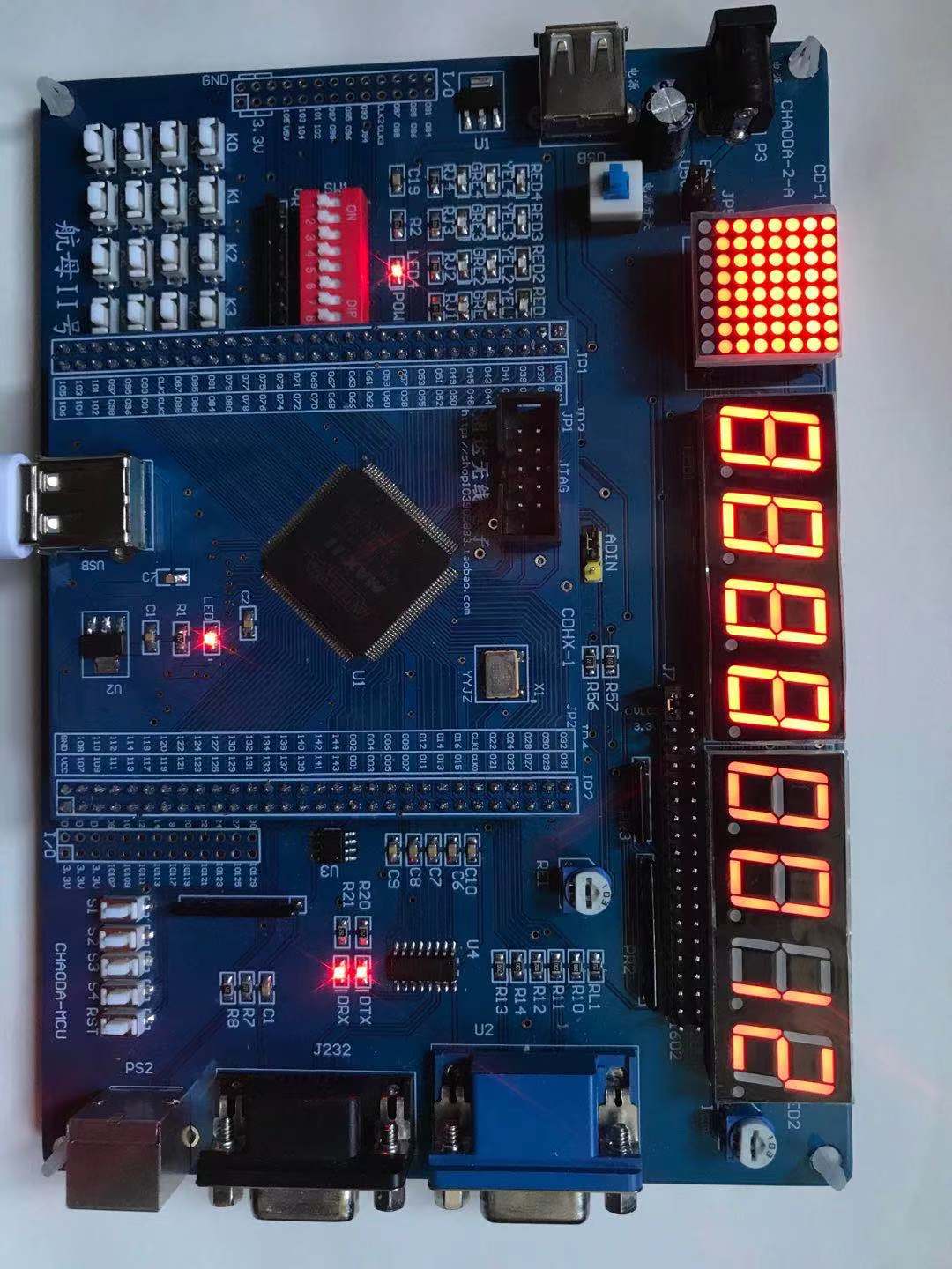
4. Overall function commissioning
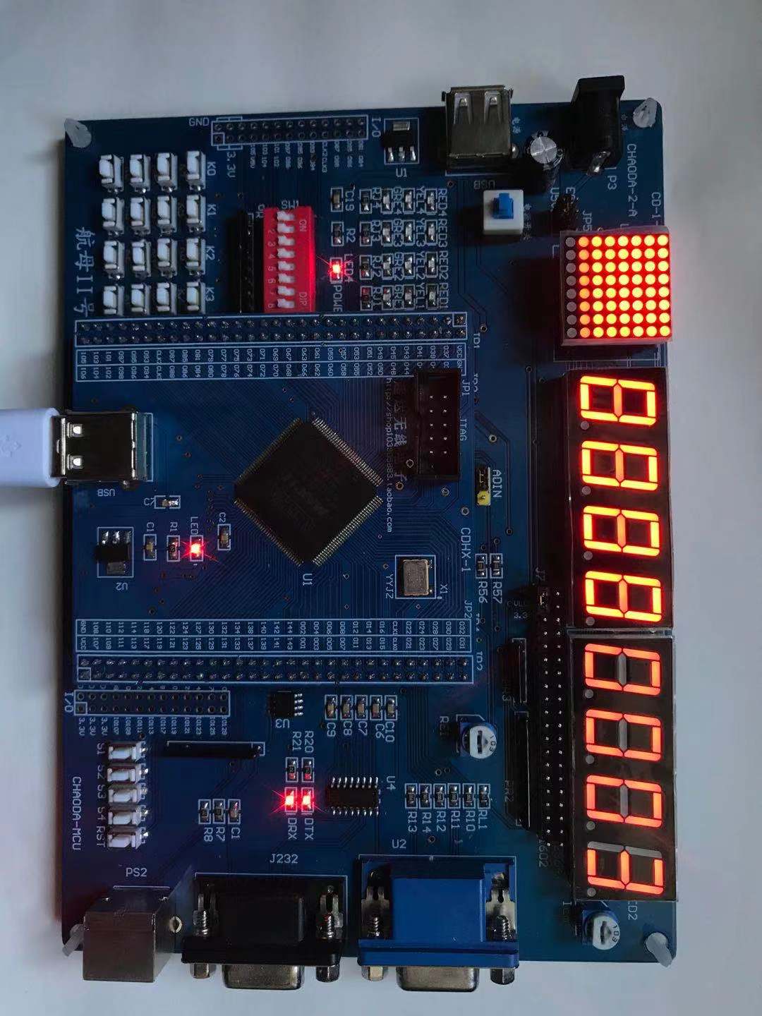
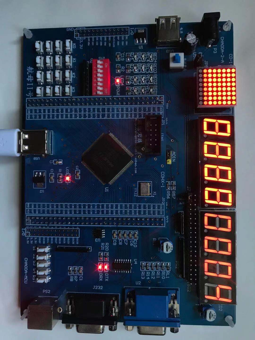
Waveform simulation is required in actual debugging. Here, we are mainly lazy and have not written test files. You can write them yourself; The debugging process is as follows: first press "12" (Figure 4-1) with the key, and then press the operator "/". After pressing the operator, the nixie tube will display "0000", then press the number key "3" (Figure 4-2), and then press the operator "/" to display the operation result (Figure 4-3).
5. Summary
The project has been packaged into github. If necessary, double-click the link directly.
https://github.com/Jeff-Ray/Calculator/tree/master