An example of Halcon two-dimensional affine transformation
Handled at: https://www.cnblogs.com/xh6300/p/7442164.html
Two dimensional affine transformation, as its name implies, is the behavior of translating, rotating, scaling and other transformations of objects in a two-dimensional plane (of course, there are other transformations, and only the three most common ones are discussed here).
The common steps of affine transformation in Halcon are as follows:
① Through Hom_ mat2d_ The identity operator creates an initialization matrix (i.e. [1.0, 0.0, 0.0, 0.0, 1.0, 0.0]);
② Based on the initialization matrix, Hom is used_ mat2d_ Translate, hom_mat2d_rotate, hom_mat2d_scale and so on to generate an affine transformation matrix; (these operators can be superimposed or reused)
③ Affine transformation is performed according to the generated transformation matrix. The operators performing affine transformation usually include: affine_trans_image,affine_trans_region,affine_trans_contour_xld, that is, affine transformation can be performed for image, region and XLD.
The following shows Hom with a complete program_ mat2d_ Translate, hom_mat2d_rotate, hom_mat2d_scale is the specific function of these three operators. (pay special attention to the program notes)
hom_mat2d_translate( : : HomMat2D, Tx, Ty : HomMat2DTranslate)
hom_mat2d_rotate( : : HomMat2D, Phi, Px, Py : HomMat2DRotate)
hom_mat2d_scale( : : HomMat2D, Sx, Sy, Px, Py : HomMat2DScale)
The pictures used in the program are as follows:
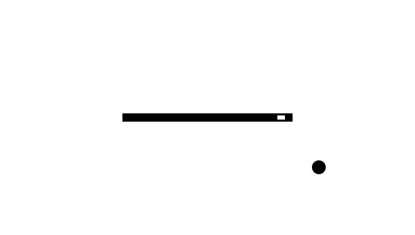
1 read_image (Image, 'hogn-1.jpg')
2 threshold (Image, Region, 0, 200)
3 opening_circle (Region, Region, 1.5)
4 connection (Region, ConnectedRegions)
5 select_shape_std (ConnectedRegions, SelectedRegions, 'max_area', 70)
6 *Get the center point of the transformation
7 area_center (SelectedRegions, Area, Row, Column)
8 dev_set_draw ('margin')
9
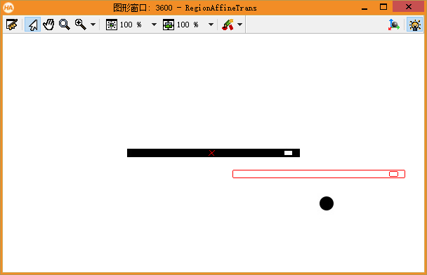
10 *hom_mat2d_translate The two parameters in mean: Tx and Ty Respectively represent Row Direction and Column Translation in direction
11 dev_display (Image)
12 disp_cross (3600, Row, Column, 10, 40)
13 hom_mat2d_identity (HomMat2DIdentity)
14 hom_mat2d_translate (HomMat2DIdentity,30, 150, HomMat2DTranslate)
15 affine_trans_region (Region, RegionAffineTrans, HomMat2DTranslate, 'nearest_neighbor')
16
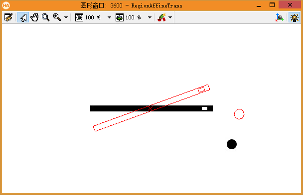
17 *hom_mat2d_rotate The three parameters in mean: rotation angle (counterclockwise is positive, radian system), rotation center row and column value
18 dev_display (Image)
19 disp_cross (3600, Row, Column, 10, 40)
20 hom_mat2d_rotate (HomMat2DIdentity, rad(20), Row, Column, HomMat2DRotate)
21 affine_trans_region (Region, RegionAffineTrans, HomMat2DRotate, 'nearest_neighbor')
22
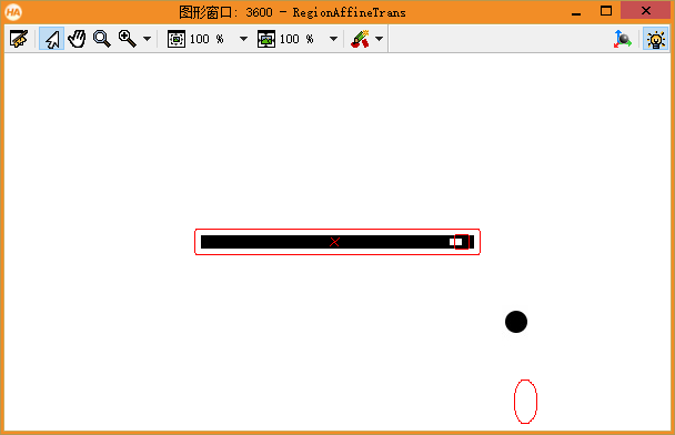
23 *hom_mat2d_scale The four parameters in mean: Sx and Sy Respectively represent Row Direction and Column Scaling factor of direction, scaling Center row and column value
24 dev_display (Image)
25 disp_cross (3600, Row, Column, 10, 40)
26 hom_mat2d_scale (HomMat2DIdentity, 2.0, 1.05, Row, Column, HomMat2DScale)
27 affine_trans_region (Region, RegionAffineTrans, HomMat2DScale, 'nearest_neighbor')
The effects are as follows:
Sometimes, affine transformation can be performed without creating an initialization matrix, such as vector_ angle_ to_ This is the case with the rigid operator.
vector_angle_to_rigid( : : Row1, Column1, Angle1, Row2, Column2, Angle2 : HomMat2D)
This operator means: first rotate the image, the rotation angle is (Angle2 - Angle1) (counterclockwise is positive), and the rotation center coordinate is (Row1, Column1). Then move the points (Row1, Column1) of the original figure to the points (Row2, Column2) one by one. The displacement in the direction of row and column is (Row2 - Row1), (Column2 - Column1) respectively,
If Row1 = Row2 and Column1 = Column2, it is completely equivalent to rotation transformation. You can perform the following procedure to feel it:
 1 read_image (Image, 'hogn-1.jpg')
 2 Row := 100
 3 Column := 200
 4 dev_display (Image)
 5
 6
 7 for Index := 1 to 150 by 1
 8     vector_angle_to_rigid (Row, Column, 0, Row, Column, rad(10), HomMat2D)
 9     disp_cross (3600, 100, 200, 10, 40)
10     affine_trans_image (Image, ImageAffinTrans, HomMat2D, 'nearest_neighbor', 'false')
11     copy_image (ImageAffinTrans, Image)
12 endfor
Vector can be_ angle_ to_ Rigid is understood as performing rotation transformation and translation transformation at the same time. The hardest thing to understand is what is the center of rotation? The following procedure can explain that if you rotate first and then translate, the rotation center is (Row1, Column1), not (Row2, Column2). (if you translate first and then rotate, the conclusion is just the opposite. You can try it.)
 1 read_image (Image, 'hogn-1.jpg')
 2 Row1 := 100
 3 Column1 := 100
 4
 5 Row2 := 100
 6 Column2 := 200
 7 dev_display (Image)
 8 *use vector_angle_to_rigid Zoom and pan
 9 vector_angle_to_rigid (Row1, Column1, 0, Row2, Column2, rad(10), HomMat2D)
10 affine_trans_image (Image, ImageAffinTrans, HomMat2D, 'nearest_neighbor', 'false')
11
12 *Zoom and pan in two steps
13 hom_mat2d_identity (HomMat2DIdentity)
14 hom_mat2d_rotate (HomMat2DIdentity, rad(10) - 0, Row1, Column1, HomMat2DRotate)
15 hom_mat2d_translate (HomMat2DRotate,Row2 - Row1, Column2 - Column1, HomMat2DTranslate)
16 *Observation imageImageAffinTrans and ImageAffinTrans_2 Can completely coincide
17 affine_trans_image (Image, ImageAffinTrans_2, HomMat2DTranslate, 'nearest_neighbor', 'false')
18
19 disp_cross (3600, Row1, Column1, 10, 40)
vector_ angle_ to_ The most commonly used occasions of rigid are algorithms such as template matching, which are usually used in find_shape_model and other operators.
The following is an example to illustrate the comprehensive application of affine transformation, that is, when the image is rotated by 90 °, find a way to transform the Region so that it can flip to the corresponding position.
The method of turning the picture 90 ° clockwise can be: rotate_image (image, ImageRotate, -90, 'constant').
But in fact, it has not only undergone rotation transformation, but also translation transformation. The most obvious evidence is that the coordinates of their central points are different in the images before and after flipping. The complete procedure is as follows:
 1 read_image (image, 'C:/Users/happy xia/Desktop/dynPic.png')
 2 binary_threshold (image, Region, 'max_separability', 'dark', UsedThreshold)
 3 dev_set_draw ('margin')
 4 connection (Region, ConnectedRegions)
 5 select_shape_std (ConnectedRegions, SelectedReg, 'max_area', 70)
 6 area_center (image, Area, Row, Column)
 7
 8 rotate_image (image, ImageRotate, -90, 'constant')
 9 area_center (ImageRotate, Area2, Row2, Column2)
10
11 hom_mat2d_identity (HomMat2DIdentity)
12 hom_mat2d_rotate (HomMat2DIdentity, -rad(90), Row, Column, HomMat2DRotate)
13 hom_mat2d_translate (HomMat2DRotate,Row2 - Row, Column2 - Column, HomMat2DTranslate)
14
15 affine_trans_region (SelectedReg, RegionAffineTrans, HomMat2DTranslate, 'constant')
The algorithm successfully achieves its goal - after the image is flipped, the originally generated Region is also flipped to the corresponding position.
Note: use rotate_ When the image operator rotates the image, if the rotation angle is not 0 °, 90 °, 180 ° or 270 °, the image actually only performs rotation transformation, not translation transformation.