Bowen catalog
Write before
At the beginning, I thought that since this is a very simple tutorial, I should only give the concept of FIFO, but I didn't expect to give the design of synchronous and asynchronous FIFO. Otherwise, I always feel the content is incomplete, or I can design my own FIFO module without worrying about the disadvantage of IP core not being universal across platforms.Let's get started.
- Personal Wechat Public Number: GA LAB
- Personal Blog Home Page
- Note: Learn to communicate!
text
Synchronized FIFO Review
The previous blog talked about the concept of synchronous FIFO and the design of synchronous FIFO. The Verilog code and VHDL code of synchronous FIFO are given, which have been tested by behavioral simulation. The links are as follows:
Minimalist tutorial on the fundamentals of GA (3) Synchronizing FIFO articles from FIFO design
$clog2() system function use
Simply mention here that a system function, $clog2(), is used in the code for synchronizing FIFO, and it is easy to use:
parameter DATA_WIDTH = 8;
parameter DATA_DEPTH = 8;

reg [DATA_WIDTH - 1 : 0] fifo_buffer[0 : DATA_DEPTH - 1];

reg [$clog2(DATA_DEPTH) - 1 : 0] wr_pointer = 0;
reg [$clog2(DATA_DEPTH) - 1 : 0] rd_pointer = 0;
For example, I defined a FIFO buffer with a depth of DATA_DEPTH = 8, what is the address (pointer) bit width?
Now you can use the system function $clog2(), which can be expressed as:
$clog2(DATA_DEPTH) // = 3;
The pointer can be defined as:
reg [$clog2(DATA_DEPTH) - 1 : 0] wr_pointer = 0;
reg [$clog2(DATA_DEPTH) - 1 : 0] rd_pointer = 0;
Comprehensive Attribute Control Resource Utilization
It is also important to mention that we all know that the implementation of FIFO in the field-bus can use distributed resources or BLOCK RAM, so how can we control it?
When using FIFO buffer space is small, we choose to use Distributed RAM; when using FIFO buffer space is large, we choose to use BLOCK RAM resources; this is a general selection principle.
We can control this by adding constraints to the design code, which we've written before
Vivado essays (1) ram_of comprehensive propertiesStyle & rom_Style?
For the synchronous FIFO described above, we can add the following constraints when defining the buffer:
(*ram_style = "distributed"*) reg [DATA_WIDTH - 1 : 0] fifo_buffer[0 : DATA_DEPTH - 1];

Or:

(*ram_style = "block"*) reg [DATA_WIDTH - 1 : 0] fifo_buffer[0 : DATA_DEPTH - 1];
To verify its usefulness, we validated the following in Vivado:
When BLOCK RAM constraints are used in design:
(*ram_style = "block"*)reg [DATA_WIDTH - 1 : 0] fifo_buffer[0 : DATA_DEPTH - 1];
The synthesized circuit diagram shows that the resource used by FIFO cache is BLOCK RAM.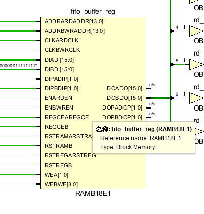
A resource utilization report is also provided:
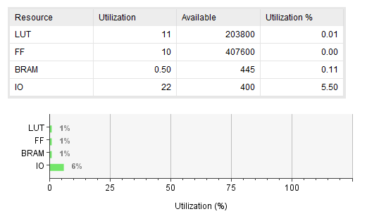
BLOCK RAM is visible, since I have only synthesized one synchronous FIFO, this Block RAM must be consumed by the FIFO buffer.
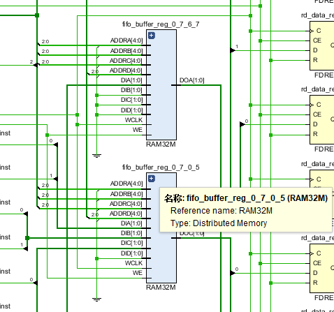
When using Distributed RAM constraints:
(*ram_style = "distributed"*)reg [DATA_WIDTH - 1 : 0] fifo_buffer[0 : DATA_DEPTH - 1];
The FIFO buffer part of the synthesized circuit diagram:
Resource utilization;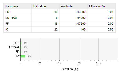
Thus, instead of using BLOCK RAM, LUT RAM, or distributed RAM, is used.
To sum up, the validity of this constraint is verified.
Asynchronous FIFO design
Review of FIFO uses
Before redesigning the asynchronous FIFO circuit, it is necessary to explain the use of FIFO, as mentioned in the previous post:
- Cross Clock Domain
In order to make data safe, correct and stable, we need to design asynchronous FIFO to interact across clock domains.As previously blogged: Talk about time series design (1) Cross-clock domain is designed, not constrained!
In time series analysis, pseudo path constraints are usually applied across clock domain paths, so we have to solve the cross-clock domain data transfer problem at design time, where asynchronous FIFO plays a key role.
- Buffer data before sending it off-chip (for example, to DRAM or SRAM)
- Buffer data for software to view later
- Store data for backup
All three of them roughly mean the same thing. To sum up, FIFO can buffer or cache data, such as sudden data, which needs to be cached before it can be read out from FIFO for processing. This also guarantees that data will not be lost.
Referring to other statements on the Internet, it is said that data is written too quickly and at long intervals, that is, abruptly.By setting a certain depth of FIFO, it can temporarily store data and smooth the subsequent processing.
Review of Asynchronous FIFO Principles
Whether synchronous FIFO or asynchronous FIFO, the general principle is consistent. First-in, first-out, naturally need not be said more. The empty judgment is based on the relationship between the read and write pointers. Also, asynchronous FIFO pointers need to be handled, such as gray code processing, to reduce the synchronization of the read pointer to the write pointer clock domain or the write pointer to the read finger.The probability of metastability occurring in the clockwise domain is because the Gray code changes only one bit at a time, which greatly reduces the probability of metastability occurring when a data is transmitted across the clock domain.The synchronization is then compared to determine the FIFO's empty state.
How does an asynchronous FIFO tell if it is full?
Before answering this question, I would like to unify how FIFO (synchronous or asynchronous) judges full?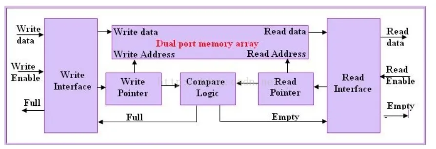
At the beginning, the read and write pointers are all 0, FIFO must be empty; after that, a series of read and write operations on FIFO have been carried out, resulting in changes in the read and write pointer relationship, which can be divided into the following two situations:
- Read faster than write, or read pointer to write pointer, if catch, that is, they are equal again, FIFO read empty;
- Write is faster than read, or the Write Pointer bend goes beyond the Append Pointer, and FIFO is full when the Write Pointer goes around the back of the Read Pointer again and coincides with the Read Pointer, that is, when the two are equal!
In synchronous FIFO, we use the counting method to judge the empty, which is also the principle. When writing a data, the counting value is added 1, and when reading out a data, the counting value is subtracted 1, as shown in the following figure:
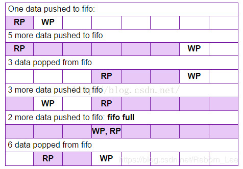
I like to use this diagram to analyze FIFO best, line by line below:
- First line: Write 1 data with a count of 1;
- Line 2: Write 5 data, count 6;
- Line 3: Read 3 data, count 3;
- Line 4: Write 3 data with a count of 6;
- Line 5: Write 2 data, count 8, equal to FIFO depth, indicating full write;
- Line 6: Read out six data with a count of 2, indicating that there are two remaining data caches in FIFO.
If you read two more data, the count is 0 and the FIFO is read empty.
Okay, we've finished analyzing how synchronous FIFOs judge to be empty. Here's how asynchronous FIFOs work.
I wrote a blog about CDC issues about the design of asynchronous FIFO s:
Talk about Cross-Clock Domain Transmission (CDC)
The blog said that synchronous FIFOs can use counting to determine full, but asynchronous FIFOs cannot because the write and read pointers are not in the same clock domain at all, and the counter cannot handle such counts.
So what to do?
The method used in the blog is to add one bit more to the bit width of the read-write pointer, which means FIFO is empty when the read-write pointer is equal, but when the write pointer and the read pointer are different at the highest bit, and the other bits are equal, that is, the write pointer is larger than the read pointer by a number of FIFO depths, indicating FIFO is full. Does this mean that the write pointer has been rounded and the read pointer has been caught up again?
That's right, it's used to solve the problem of judging FIFO full without counting.
This only solves the problem of determining the empty space, that is, determining the relationship between the pointers!
So the next question is how to judge?
Since the read and write pointers are not in the same clock domain, they need to be synchronized to the same clock domain to determine the size.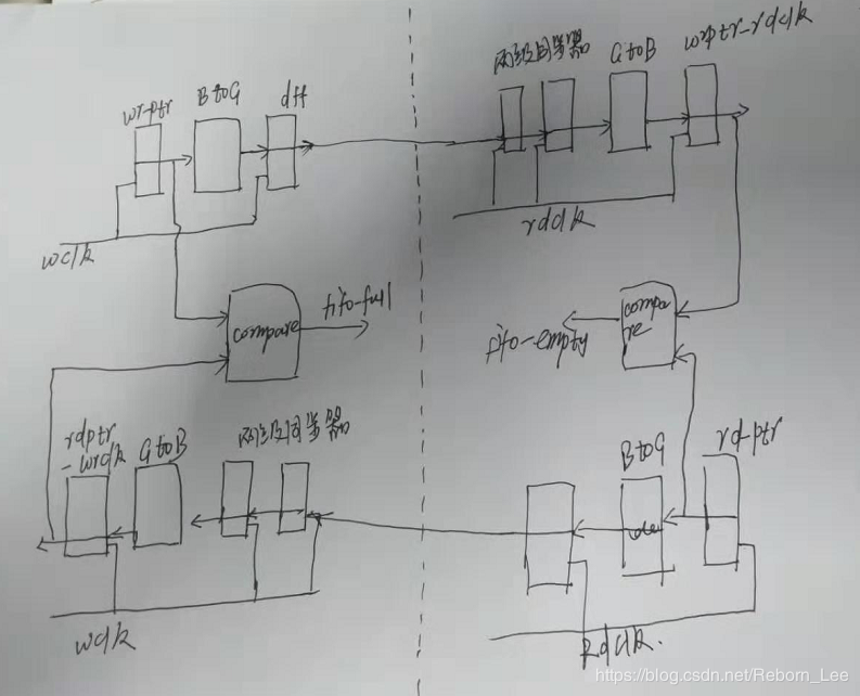
The specific operation is to read and write in their respective clock domains, at the same time:
- When deciding whether to write full, you need to convert the read pointer to gray code, then synchronize it to the write clock field, and compare it with the write pointer to determine if it is full!
Careful people are afraid to find that there is a small interlude here. When the reading pointer is converted to gray code and synchronized to the writing clock field, the reading and writing pointers may also increase. In this case, when the synchronized reading pointer is equal to the writing pointer (excluding the highest bit), the actual reading pointer may have changed. In fact, there is still a few spaces left to write.!But is there a problem with this design?No problem!This is called conservative design and can increase FIFO security.
Here is a diagram to determine if it is full: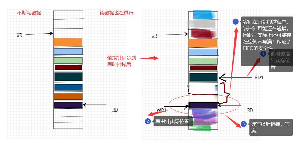
Above is the case of full judgement, and below is an analysis of the possible scenarios of empty judgement:
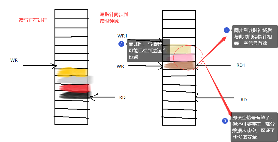
- When deciding whether to read null, you need to synchronize the write pointer to the read clock field. The specific process is to convert the write pointer to gray code, then synchronize to the read clock field, and then compare with the read pointer. If the two are equal, the null marker is positioned!
Or there is the same episode as in the first case, when the write pointer is converted to gray code and synchronized to the read clock field, both the write pointer and the read pointer may still be increasing, so when the two are equal, the write pointer may have written a few more spaces and not actually read empty.
That's the problem. Is there a problem with this operation?No problem, this also ensures the security of FIFO and prevents it from being read out.
The following is a freehand diagram:
At this point, the asynchronous FIFO of this design method is finished. Here are the design issues.
Asynchronous FIFO design
If you carefully analyze the implementation of the asynchronous FIFO described above, you will write the implementation code in minutes, and my version is as follows:
`timescale 1ns / 1ps
////////////////////////////////////////////////////
// Engineer: Reborn Lee
// Module Name: asy_fifo
// https://blog.csdn.net/Reborn_Lee
////////////////////////////////////////////////////


module asy_fifo#(
	parameter DATA_WIDTH = 8,
	parameter DATA_DEPTH = 32
	)(
	input wr_clk,
	input wr_rst,
	input wr_en,
	input [DATA_WIDTH - 1 : 0] wr_data,
	output reg full,

	input rd_clk,
	input rd_rst,
	input rd_en,
	output reg [DATA_WIDTH - 1 : 0] rd_data,
	output reg empty

    );


	// define FIFO buffer
	reg [DATA_WIDTH - 1 : 0] fifo_buffer[0 : DATA_DEPTH - 1];

	//define the write and read pointer and
	//pay attention to the size of pointer which should be greater one to normal

	reg [$clog2(DATA_DEPTH) : 0] wr_pointer = 0, rd_pointer = 0;

	//write data to fifo buffer and wr_pointer control
	always@(posedge wr_clk) begin
		if(wr_rst) begin
			wr_pointer <= 0;
		end
		else if(wr_en) begin
			wr_pointer <= wr_pointer + 1;
			fifo_buffer[wr_pointer] <= wr_data;
		end

	end

	//read data from fifo buffer and rd_pointer control
	always@(posedge rd_clk) begin
		if(rd_rst) begin
			rd_pointer <= 0;
		end
		else if(rd_en) begin
			rd_pointer <= rd_pointer + 1;
			rd_data <= fifo_buffer[rd_pointer];
		end

	end

	//wr_pointer and rd_pointer translate into gray code

	wire [$clog2(DATA_DEPTH) : 0] wr_ptr_g, rd_ptr_g;

	assign wr_ptr_g = wr_pointer ^ (wr_pointer >>> 1);
	assign rd_ptr_g = rd_pointer ^ (rd_pointer >>> 1);


	//wr_pointer after gray coding synchronize into read clock region
	reg [$clog2(DATA_DEPTH) : 0] wr_ptr_gr, wr_ptr_grr, rd_ptr_gr, rd_ptr_grr;

	always@(rd_clk) begin
		if(rd_rst) begin
			wr_ptr_gr <= 0;
			wr_ptr_grr <= 0;
		end
		else begin
			wr_ptr_gr <= wr_ptr_g;
			wr_ptr_grr <= wr_ptr_gr;
		end
	end


	//rd_pointer after gray coding synchronize into  write clock region
	always@(wr_clk) begin
		if(wr_rst) begin
			rd_ptr_gr <= 0;
			rd_ptr_grr <= 0;
		end
		else begin
			rd_ptr_gr <= rd_ptr_g;
			rd_ptr_grr <= rd_ptr_gr;
		end
	end

	// judge full or empty

	always@(posedge rd_clk) begin
		if(rd_rst) empty <= 0;
		else if(wr_ptr_grr == rd_ptr_g) begin
			empty <= 1;
		end
		else empty <= 0;
 	end

 	always@(posedge wr_clk) begin
 		if(wr_rst) full <= 0;
 		else if( (rd_ptr_grr[$clog2(DATA_DEPTH) - 1 : 0] == wr_ptr_g[$clog2(DATA_DEPTH) - 1 : 0])
 			&& ( rd_ptr_grr[$clog2(DATA_DEPTH)] != wr_ptr_g[$clog2(DATA_DEPTH)] ) ) begin
 			full <= 1;
 		end
 		else full <= 0;
 	end


endmodule
Matters needing attention
- Read and write pointer width is $clog2(DATA_DEPTH) + 1, which should be defined as:
reg [$clog2(DATA_DEPTH) : 0] wr_pointer = 0, rd_pointer = 0;
- Secondly, when you are empty, compare the write pointer to the read pointer that is converted to Gray code and synchronized to the read clock field. The comparison code is as follows:
always@(posedge rd_clk) begin
		if(rd_rst) empty <= 0;
		else if(wr_ptr_grr == rd_ptr_g) begin
			empty <= 1;
		end
		else empty <= 0;
 	end
Make sure that the next reading cycle empty signal is equal to 1;
- For a full full full signal, it is important to compare the read pointer that is converted to Gray code and synchronized to the write clock field with the write clock that is converted to Gray code on the condition that the highest bit is different, but the other bits are the same.
always@(posedge wr_clk) begin
 		if(wr_rst) full <= 0;
 		else if( (rd_ptr_grr[$clog2(DATA_DEPTH) - 1 : 0] == wr_ptr_g[$clog2(DATA_DEPTH) - 1 : 0])
 			&& ( rd_ptr_grr[$clog2(DATA_DEPTH)] != wr_ptr_g[$clog2(DATA_DEPTH)] ) ) begin
 			full <= 1;
 		end
 		else full <= 0;
 	end
- Finally, the way to convert to Gray Code is to combine logic, that is:
//wr_pointer and rd_pointer translate into gray code

	wire [$clog2(DATA_DEPTH) : 0] wr_ptr_g, rd_ptr_g;

	assign wr_ptr_g = wr_pointer ^ (wr_pointer >>> 1);
	assign rd_ptr_g = rd_pointer ^ (rd_pointer >>> 1);
Of course, you can also use time series logic.
Asynchronous FIFO simulation
We conduct a behavioral simulation of the above design, giving my test file first:
`timescale 1ns/1ps
module asy_fifo_tb;
	parameter DATA_WIDTH = 8;
	parameter DATA_DEPTH = 16;

	reg wr_clk;
	reg wr_rst;
	reg wr_en;
	reg [DATA_WIDTH - 1 : 0] wr_data;
	wire full;

	reg rd_clk;
	reg rd_rst;
	reg rd_en;
	wire [DATA_WIDTH - 1 : 0] rd_data;
	wire empty;

	initial begin
		wr_clk = 0;
		forever begin
			#5 wr_clk = ~wr_clk;
		end
	end

	initial begin
		rd_clk = 0;
		forever begin
			#10 rd_clk = ~rd_clk;
		end
	end

	initial begin
		wr_rst = 1;
		rd_rst = 1;
		wr_en = 0;
		rd_en = 0;
		#30
		wr_rst = 0;
		rd_rst = 0;

		//write data into fifo buffer
		@(negedge wr_clk)
		wr_data = $random;
		wr_en = 1;

		repeat(7) begin
			@(negedge wr_clk)
			wr_data = $random; // write into fifo 8 datas in all;
		end

		// read parts
		@(negedge wr_clk)
		wr_en = 0;

		@(negedge rd_clk)
		rd_en = 1;

		repeat(7) begin
			@(negedge rd_clk);  // read empty
		end
		@(negedge rd_clk)
		rd_en = 0;

		//write full
		# 150

		@(negedge wr_clk)
		wr_en = 1;
		wr_data = $random;

		repeat(15) begin
		@(negedge wr_clk)
			wr_data = $random;
		end

		@(negedge wr_clk)
		wr_en = 0;


		#50 $finish;


	end


	asy_fifo #(
			.DATA_WIDTH(DATA_WIDTH),
			.DATA_DEPTH(DATA_DEPTH)
		) inst_asy_fifo (
			.wr_clk  (wr_clk),
			.wr_rst  (wr_rst),
			.wr_en   (wr_en),
			.wr_data (wr_data),
			.full    (full),
			.rd_clk  (rd_clk),
			.rd_rst  (rd_rst),
			.rd_en   (rd_en),
			.rd_data (rd_data),
			.empty   (empty)
		);


endmodule
The simulated waveform is: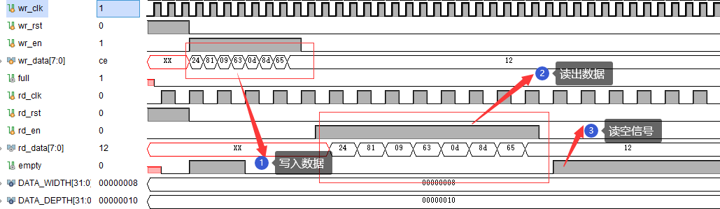
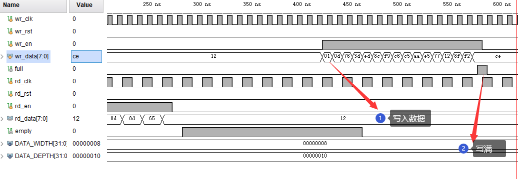
The simulation passes and the function meets expectations.
Since this blog was written a little long, almost a day, so here it is!It must be said that this is certainly not the only way to implement asynchronous FIFO, there are many other ways to achieve it, you can try it yourself.
If there is more interesting knowledge or experience about FIFO in the future, I will continue to add!
Reference material
Make a friend
- Personal Wechat Public Number: GA LAB;
- Field Program/IC Technology Exchange 2020