Daily nagging:
This year, the South China competition area is over, and there are still more than 20 days for the national competition, which can be regarded as a few days of leisure. I have a special feeling for Lora. I have been using it since the last Jichuang competition. At first, I was always attached to the WiFi module, but the WiFi module was not friendly to FPGA white programmers. Then my classmates recommended this wireless spread spectrum module to me. With the continuous maturity of Lora technology, Lora has been widely used at home and abroad. People in this field are not unfamiliar with Lora. Lora is a wireless communication technology dedicated to long-distance and low-power consumption. Its modulation mode greatly increases the communication distance compared with other communication modes. It can be widely used in the field of long-distance and low-speed Internet of things wireless communication in various occasions. Here is a brief talk about how to design Lora and robot communication in Robei.
1, What is Lora module
To understand LoRa module, we must first understand LoRa. LoRa is a kind of low-power Wan communication technology. It is an ultra long-distance wireless transmission technology based on spread spectrum technology adopted and promoted by Semtech company. It is a unique modulation lattice generated by Semtech RF part. LoRa module is a wireless data transmission module based on SX1276/1278 chip of Semtech company. This chip has small integration scale and high efficiency, so that LoRa module has high receiving sensitivity.
LoRa's advantages are mainly reflected in the following aspects:
1. The sensitivity of the receiver is greatly improved and the power consumption is reduced.
The link budget of up to 157db enables the communication distance to reach 15km (environment related). The receiving current is only 10mA and the sleep current is 200nA, which greatly delays the service life of the battery.
2. The gateway / concentrator based on this technology supports parallel processing of multi-channel and multi data rate, and the system capacity is large.
The gateway is the bridge between the node and the IP network (through 2G/3G/4G or Ethernet). Each gateway can handle 5 million communications between nodes every day (assuming that 10 bytes are sent each time, and the network occupancy rate is 10%). If the gateway is installed at the location of the existing mobile communication base station with a transmission power of 20dBm(100mW), it can cover about 2km in the densely built urban environment and 10km in the suburbs with low density.
3. The system based on terminal and concentrator / gateway can support ranging and positioning.
LoRa's measurement of distance is based on the air transmission time of signal rather than the traditional RSSI (received signal sterngth indication), while positioning is based on the measurement of air transmission time difference between multipoint (Gateway) and one point (node). Its positioning accuracy can reach 5m (assuming a range of 10km).
4. High confidentiality and concealment
With LoRa modulation, traditional wireless devices cannot obtain and analyze it, and can still communicate normally when the average power in band is lower than the bottom noise.
2, What is the mode of communication
1. Module selection
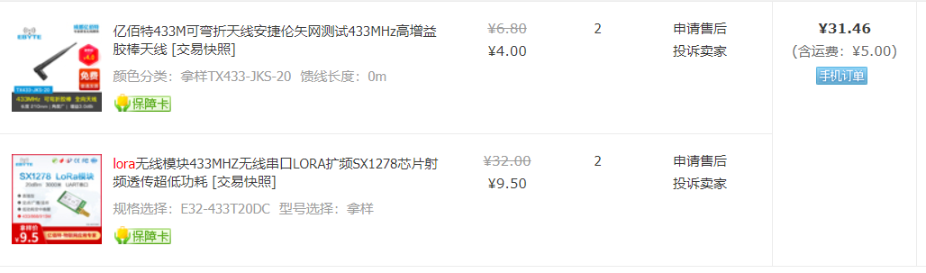
There are many lora modules of a treasure. Which module to choose?
It is recommended to choose yibaite. Their family specializes in lora modules. There are various models and the price is also very cheap. The module plus antenna is only 31RMB for two sets. Moreover, the module of their family is much more convenient to write programs than others. It is very troublesome to think of the lora module of punctual atoms, and various environments should be configured for communication. With yibaite, just program with UART protocol.
2. Parameters and settings
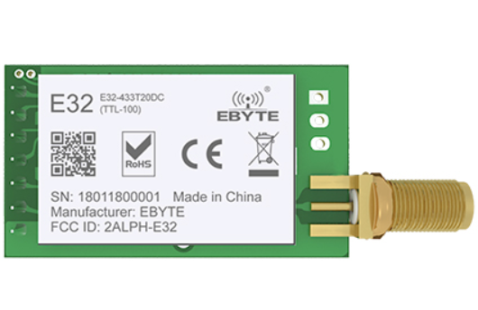
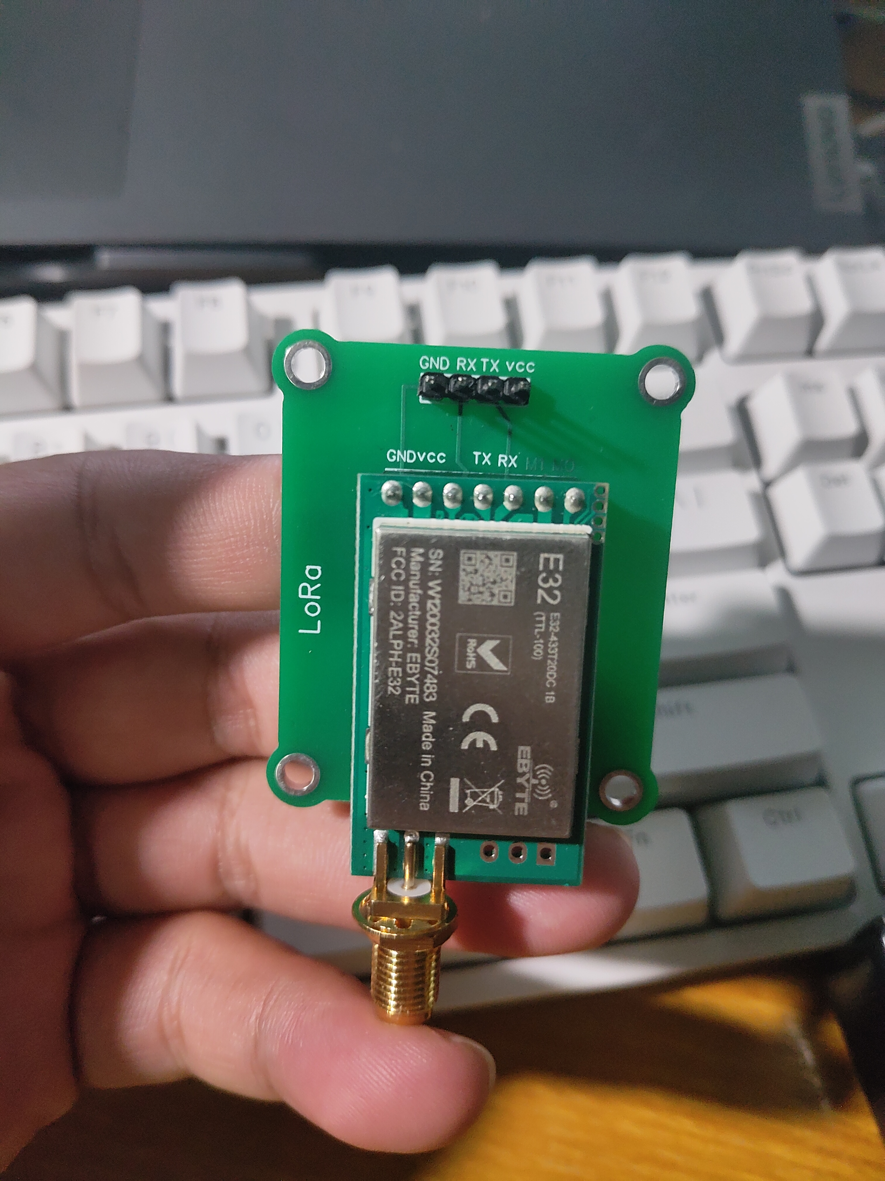
I chose E32-433T20DC LoRa spread spectrum, and the following are its parameters:
Chip scheme: SX1278
Carrier frequency: 410~441MHz
Transmitting power: 10~20dBm
Communication distance: 3km
Communication interface: UART
Default baud rate: 9600
Net product volume: 6.3 ± 0.1g
Product Description: it is embedded with high-speed and low-power MCU and high-performance LoRa spread spectrum chip SX1278. It adopts efficient cyclic interleaving error correction and detection coding, which greatly improves the anti-interference and sensitivity. The transmission power is 100mW, low power consumption, wireless wake-up function, and LoRa spread spectrum can bring longer communication distance.
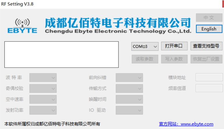
Here, the baud rate is 9600 by default. You can download the APP on their official website to modify the baud rate and other parameters.
3. Wiring mode
1. Communication wiring
It can be seen from the following figure that the two RXD pins are connected to the TX board in the development mode. Generally, the two RXD pins are connected to the TX board in the development mode. It can be seen that the two RXD pins are connected to the TX board in the development mode; 5 pin ignore, just hang in the air; 6 is VCC, connected to power supply 3.3V-5V.
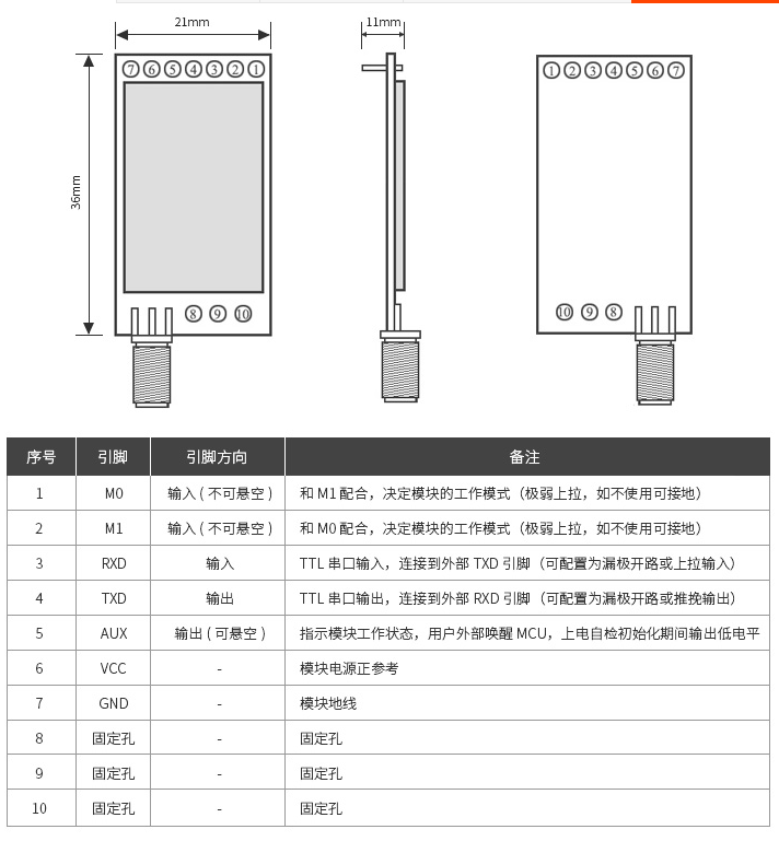
Here, I think there are too many lines connecting the bread board, which is messy, so I draw a fast and simple expansion board:
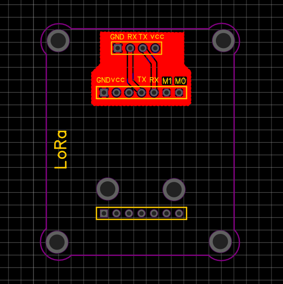
With the expansion board, it is very convenient, just like ordinary serial communication.
2. Parameter modification wiring
As mentioned above, the baud rate of the module can be modified through the software on the official website. If the parameters are modified, it is mainly to set M1 and M2 to high level, that is, pull them up, based on the previous section. Let's take a look at the work selection table of the module; After wiring, directly connect to the computer through CH340 module, open APP, read parameters, modify and save them.

3, Robei programming
1. First, build the top layer, open Robei EDA, and new a module: robei_lora
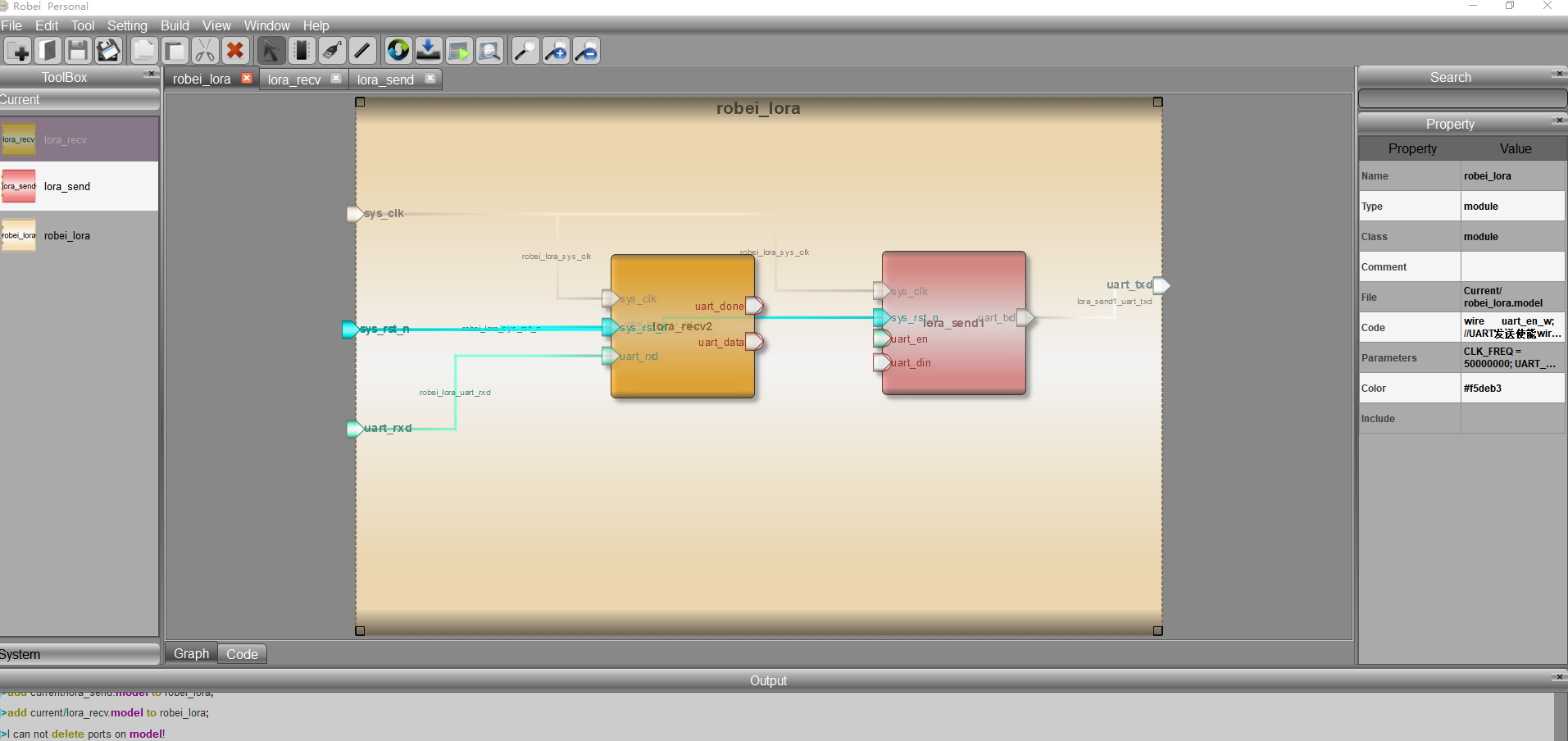
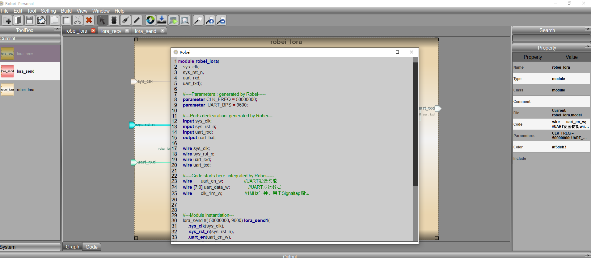
module robei_lora(
	sys_clk,
	sys_rst_n,
	uart_rxd,
	uart_txd);

	//----Parameters:: generated by Robei-----
	parameter CLK_FREQ = 50000000;
	parameter  UART_BPS = 9600;

	//---Ports declearation: generated by Robei---
	input sys_clk;
	input sys_rst_n;
	input uart_rxd;
	output uart_txd;

	wire sys_clk;
	wire sys_rst_n;
	wire uart_rxd;
	wire uart_txd;

	//----Code starts here: integrated by Robei-----
	wire       uart_en_w;                 //UART send enable
	wire [7:0] uart_data_w;               //UART send data
	wire       clk_1m_w;                  //1MHz clock for Signaltap debugging


	//---Module instantiation---
	lora_send #( 50000000, 9600) lora_send1(
		.sys_clk(sys_clk),
		.sys_rst_n(sys_rst_n),
		.uart_en(uart_en_w),
		.uart_din(uart_data_w),
		.uart_txd(uart_txd));

	lora_recv #( 50000000, 9600) lora_recv2(
		.sys_clk(sys_clk),
		.sys_rst_n(sys_rst_n),
		.uart_rxd(uart_rxd),
		.uart_done(uart_en_w),
		.uart_data(uart_data_w));

endmodule    //robei_lora
2. Write a receiving module: lora_recv
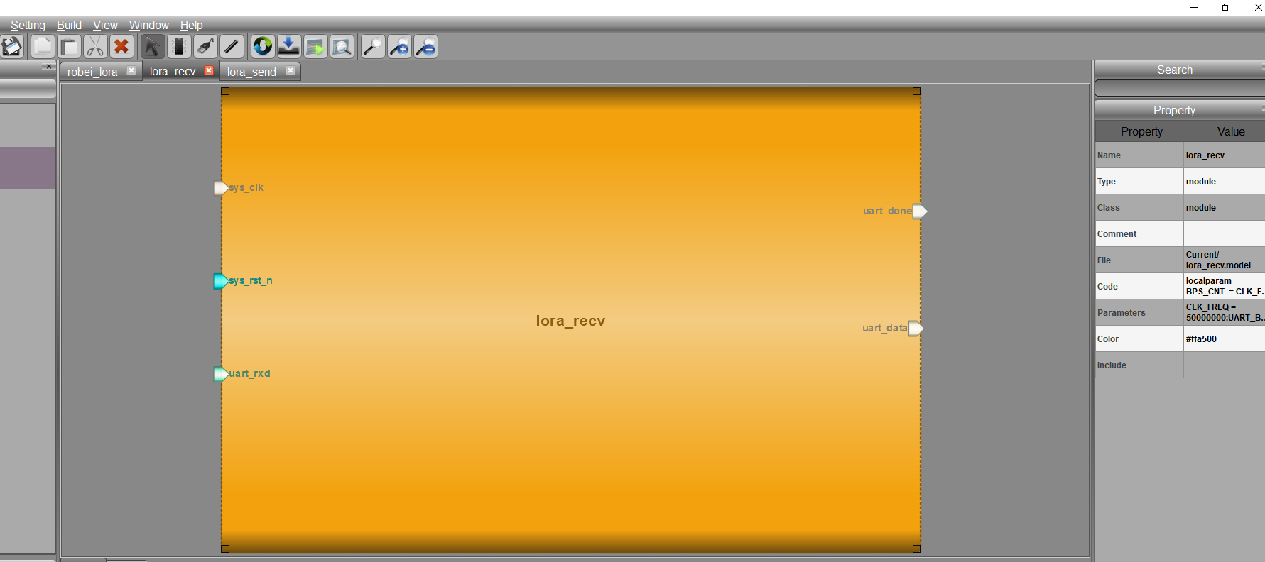
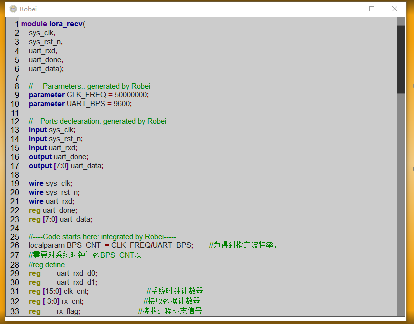
module lora_recv(
	sys_clk,
	sys_rst_n,
	uart_rxd,
	uart_done,
	uart_data);

	//----Parameters:: generated by Robei-----
	parameter CLK_FREQ = 50000000;
	parameter UART_BPS = 9600;

	//---Ports declearation: generated by Robei---
	input sys_clk;
	input sys_rst_n;
	input uart_rxd;
	output uart_done;
	output [7:0] uart_data;

	wire sys_clk;
	wire sys_rst_n;
	wire uart_rxd;
	reg uart_done;
	reg [7:0] uart_data;

	//----Code starts here: integrated by Robei-----
	localparam BPS_CNT  = CLK_FREQ/UART_BPS;        //To get the specified baud rate,
	//BPS needs to be counted on the system clock_ CNT times
	//reg define
	reg        uart_rxd_d0;
	reg        uart_rxd_d1;
	reg [15:0] clk_cnt;                             //System clock counter
	reg [ 3:0] rx_cnt;                              //Receive data counter
	reg        rx_flag;                             //Receive process flag signal
	reg [ 7:0] rxdata;                              //Receive data register

	//wire define
	wire       start_flag;
	//Capture the falling edge (start bit) of the receiving port to obtain a pulse signal of one clock cycle
	assign  start_flag = uart_rxd_d1 & (~uart_rxd_d0);

	//Delay the data of UART receiving port by two clock cycles
	always @(posedge sys_clk or negedge sys_rst_n) begin
	    if (!sys_rst_n) begin
	        uart_rxd_d0 <= 1'b0;
	        uart_rxd_d1 <= 1'b0;
	    end
	    else begin
	        uart_rxd_d0  <= uart_rxd;
	        uart_rxd_d1  <= uart_rxd_d0;
	    end
	end

	//When pulse signal start_ When the flag arrives, it enters the receiving process
	always @(posedge sys_clk or negedge sys_rst_n) begin
	    if (!sys_rst_n)
	        rx_flag <= 1'b0;
	    else begin
	        if(start_flag)                          //Start bit detected
	            rx_flag <= 1'b1;                    //Enter the receiving process, flag bit rx_flag pull up
	        else if((rx_cnt == 4'd9)&&(clk_cnt == BPS_CNT/2))
	            rx_flag <= 1'b0;                    //When the count reaches the middle of the stop bit, the receiving process is stopped
	        else
	            rx_flag <= rx_flag;
	    end
	end

	//After entering the receiving process, start the system clock counter and received data counter
	always @(posedge sys_clk or negedge sys_rst_n) begin
	    if (!sys_rst_n) begin
	        clk_cnt <= 16'd0;
	        rx_cnt  <= 4'd0;
	    end
	    else if ( rx_flag ) begin                   //In receiving process
	            if (clk_cnt < BPS_CNT - 1) begin
	                clk_cnt <= clk_cnt + 1'b1;
	                rx_cnt  <= rx_cnt;
	            end
	            else begin
	                clk_cnt <= 16'd0;               //The system clock is cleared after counting for one baud rate cycle
	                rx_cnt  <= rx_cnt + 1'b1;       //At this time, the received data counter is incremented by 1
	            end
	        end
	        else begin                              //The receiving process ends and the counter is cleared
	            clk_cnt <= 16'd0;
	            rx_cnt  <= 4'd0;
	        end
	end

	//Register uart receiving port data according to the receiving data counter
	always @(posedge sys_clk or negedge sys_rst_n) begin
	    if ( !sys_rst_n)
	        rxdata <= 8'd0;
	    else if(rx_flag)                            //The system is in the receiving process
	        if (clk_cnt == BPS_CNT/2) begin         //Judge that the system clock counter counts to the middle of the data bit
	            case ( rx_cnt )
	             4'd1 : rxdata[0] <= uart_rxd_d1;   //Lowest register data bit
	             4'd2 : rxdata[1] <= uart_rxd_d1;
	             4'd3 : rxdata[2] <= uart_rxd_d1;
	             4'd4 : rxdata[3] <= uart_rxd_d1;
	             4'd5 : rxdata[4] <= uart_rxd_d1;
	             4'd6 : rxdata[5] <= uart_rxd_d1;
	             4'd7 : rxdata[6] <= uart_rxd_d1;
	             4'd8 : rxdata[7] <= uart_rxd_d1;   //Highest bit of registered data bit
	             default:;
	            endcase
	        end
	        else
	            rxdata <= rxdata;
	    else
	        rxdata <= 8'd0;
	end

	//After the data is received, the flag signal is given and the received data is registered and output
	always @(posedge sys_clk or negedge sys_rst_n) begin
	    if (!sys_rst_n) begin
	        uart_data <= 8'd0;
	        uart_done <= 1'b0;
	    end
	    else if(rx_cnt == 4'd9) begin               //When the received data counter counts to the stop bit
	        uart_data <= rxdata;                    //Register output received data
	        uart_done <= 1'b1;                      //And pull up the reception completion flag
	    end
	    else begin
	        uart_data <= 8'd0;
	        uart_done <= 1'b0;
	    end
	end


endmodule    //lora_recv
3. Write a sending module: lora_send
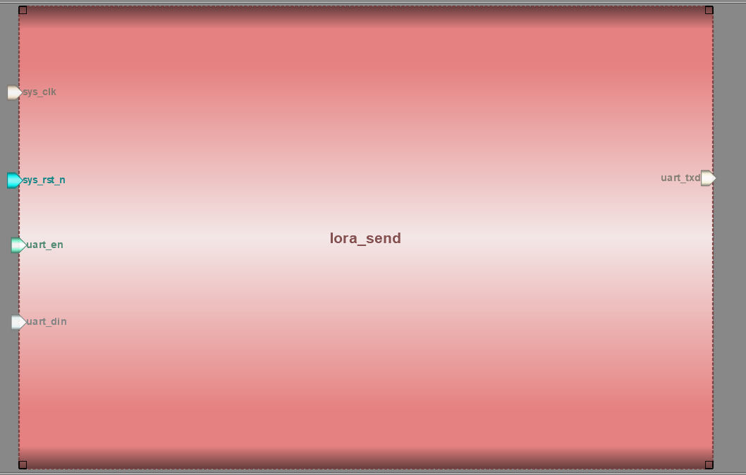
module lora_send(
	sys_clk,
	sys_rst_n,
	uart_en,
	uart_din,
	uart_txd);

	//----Parameters:: generated by Robei-----
	parameter CLK_FREQ = 50000000;
	parameter UART_BPS = 9600;

	//---Ports declearation: generated by Robei---
	input sys_clk;
	input sys_rst_n;
	input uart_en;
	input [7:0] uart_din;
	output uart_txd;

	wire sys_clk;
	wire sys_rst_n;
	wire uart_en;
	wire [7:0] uart_din;
	reg uart_txd;

	//----Code starts here: integrated by Robei-----
	localparam BPS_CNT  = CLK_FREQ/UART_BPS;    //In order to obtain the specified baud rate, the system clock is counted BPS_CNT times

	//reg define
	reg        uart_en_d0;
	reg        uart_en_d1;
	reg [15:0] clk_cnt;                         //System clock counter
	reg [ 3:0] tx_cnt;                          //Send data counter
	reg        tx_flag;                         //Send process flag signal
	reg [ 7:0] tx_data;                         //Deposit and send data

	//wire define
	wire       en_flag;

	//Capture uart_en rising edge, get a clock cycle pulse signal
	assign en_flag = (~uart_en_d1) & uart_en_d0;

	//Send enable signal UART to_ EN delays two clock cycles
	always @(posedge sys_clk or negedge sys_rst_n) begin
	    if (!sys_rst_n) begin
	        uart_en_d0 <= 1'b0;
	        uart_en_d1 <= 1'b0;
	    end
	    else begin
	        uart_en_d0 <= uart_en;
	        uart_en_d1 <= uart_en_d0;
	    end
	end

	//When pulse signal en_ When the flag arrives, it registers the data to be sent and enters the sending process
	always @(posedge sys_clk or negedge sys_rst_n) begin
	    if (!sys_rst_n) begin
	        tx_flag <= 1'b0;
	        tx_data <= 8'd0;
	    end
	    else if (en_flag) begin                 //Send enable rising edge detected
	            tx_flag <= 1'b1;                //Enter the transmission process, flag bit tx_flag pull up
	            tx_data <= uart_din;            //Register data to be sent
	        end
	        else
	        if ((tx_cnt == 4'd9)&&(clk_cnt == BPS_CNT/2))
	        begin                               //When the count reaches the middle of the stop bit, the transmission process is stopped
	            tx_flag <= 1'b0;                //The sending process ends with the flag bit tx_flag down
	            tx_data <= 8'd0;
	        end
	        else begin
	            tx_flag <= tx_flag;
	            tx_data <= tx_data;
	        end
	end

	//After entering the sending process, start the system clock counter and sending data counter
	always @(posedge sys_clk or negedge sys_rst_n) begin
	    if (!sys_rst_n) begin
	        clk_cnt <= 16'd0;
	        tx_cnt  <= 4'd0;
	    end
	    else if (tx_flag) begin                 //In sending process
	        if (clk_cnt < BPS_CNT - 1) begin
	            clk_cnt <= clk_cnt + 1'b1;
	            tx_cnt  <= tx_cnt;
	        end
	        else begin
	            clk_cnt <= 16'd0;               //The system clock is cleared after counting for one baud rate cycle
	            tx_cnt  <= tx_cnt + 1'b1;       //At this time, the transmission data counter is incremented by 1
	        end
	    end
	    else begin                              //End of sending process
	        clk_cnt <= 16'd0;
	        tx_cnt  <= 4'd0;
	    end
	end

	//Assign a value to the uart send port according to the send data counter
	always @(posedge sys_clk or negedge sys_rst_n) begin
	    if (!sys_rst_n)
	        uart_txd <= 1'b1;
	    else if (tx_flag)
	        case(tx_cnt)
	            4'd0: uart_txd <= 1'b0;         //Start bit
	            4'd1: uart_txd <= tx_data[0];   //Lowest bit of data
	            4'd2: uart_txd <= tx_data[1];
	            4'd3: uart_txd <= tx_data[2];
	            4'd4: uart_txd <= tx_data[3];
	            4'd5: uart_txd <= tx_data[4];
	            4'd6: uart_txd <= tx_data[5];
	            4'd7: uart_txd <= tx_data[6];
	            4'd8: uart_txd <= tx_data[7];   //Highest bit of data
	            4'd9: uart_txd <= 1'b1;         //Stop bit
	            default: ;
	        endcase
	    else
	        uart_txd <= 1'b1;                   //When idle, the sending port is high
	end


endmodule    //lora_send
4. Just add these two sub modules to the top-level module connection.
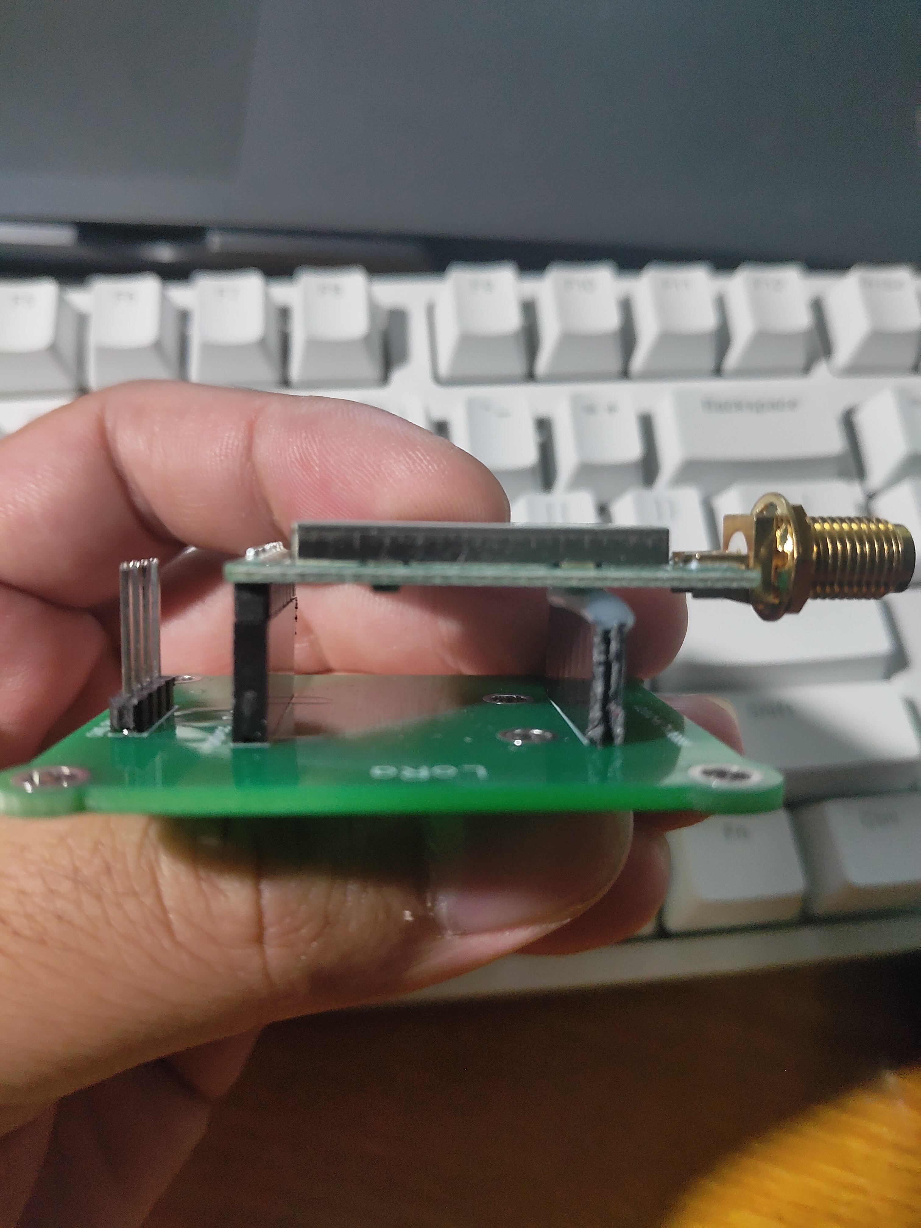
5. Physical map
Lower machine:
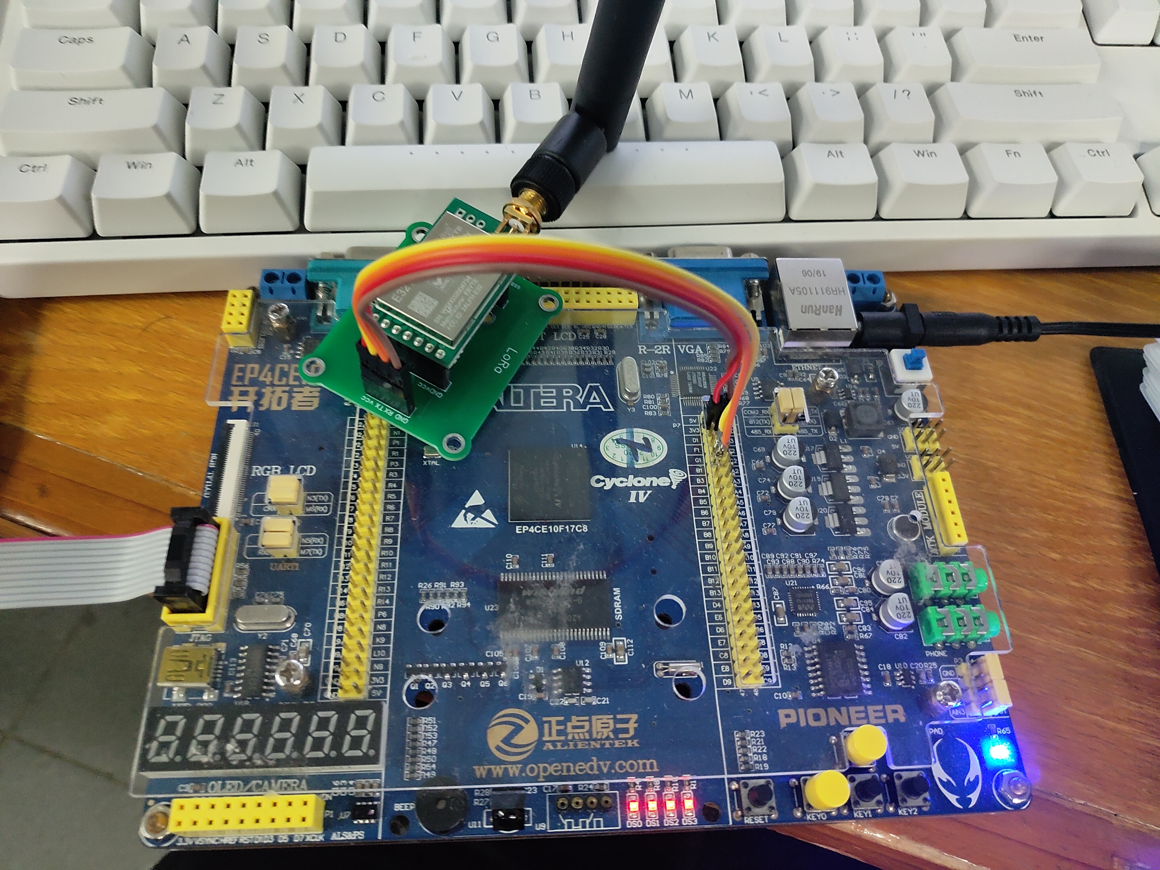
Upper computer:
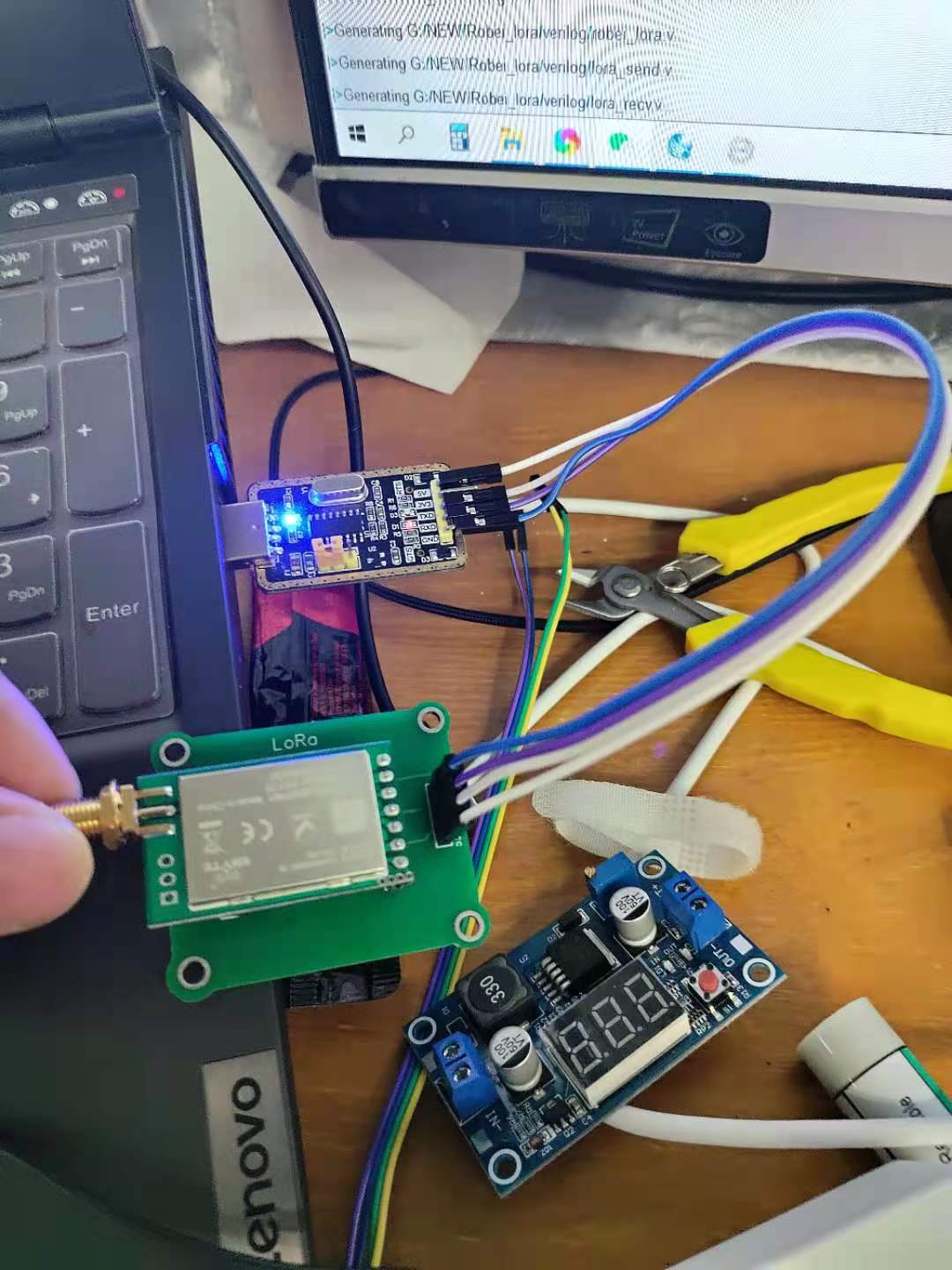
After wiring, the loop communication between the upper computer and the lower computer can be realized.
What some students need to use is that the lower computer sends the specified instructions to the upper computer. For example, when the human body detection module detects a person, it sends the discoverer to the upper computer. Here we meet everyone together.
After pressing the key, the development board sends Fa Xian to the upper computer through Lora. Students who need other instructions can modify it by themselves.
module UART(clk, rst, rxd, txd, en, seg_data, key_input, lowbit);
input clk,rst;
input rxd; //Serial data receiver
input key_input; //Key input
output[7:0] en /*synthesis keep*/ ;
output[7:0] seg_data;
reg[7:0] seg_data;
output txd; //Serial data transmitter
output lowbit;

//***************************inner reg*******************************//
reg[15:0] div_reg; //Frequency division counter. The frequency division value is determined by baud rate. After frequency division, a clock with a frequency of 8 times baud rate is obtained
reg[2:0] div8_tras_reg; //The count value of this register corresponds to the number of time slots currently located at the time of transmission
reg[2:0] div8_rec_reg; //The count value of this register corresponds to the number of time slots currently located at the time of reception
reg[3:0] state_tras; //Send status register
reg[3:0] state_rec; //Accept status register
reg clkbaud_tras; //Transmission enable signal with baud rate as frequency
reg clkbaud_rec; //Receive enable signal at baud rate
reg clkbaud8x; //The function of a clock with a frequency of 8 times baud rate is to divide the clock cycle of sending or receiving a bit into 8 time slots
reg recstart; //Start sending flag
reg recstart_tmp;
reg trasstart; //Start acceptance flag
reg rxd_reg1; //Receive register 1
reg rxd_reg2; //Receiving register 2 uses two-level cache because the received data is asynchronous signal
reg txd_reg; //Transmit register
reg[7:0] rxd_buf  /*synthesis keep*/ ; //Accept data cache
reg[7:0] txd_buf /*synthesis keep*/ ; //Send data cache
reg[2:0] send_state /*synthesis keep*/ ; //Send the "Welcome" string to the PC every time you press the key, which is the send status register
reg[19:0] cnt_delay; //Delay debounce counter
reg start_delaycnt; //Start delay count flag
reg key_entry1, key_entry2;//Make sure there is a key press flag
parameter div_par = 16'h145; //The value of frequency division parameter is calculated from the corresponding baud rate. The clock frequency divided according to this parameter is 8 times the wave magnification
//Times, the value here corresponds to the baud rate of 9600, that is, the divided clock frequency is 9600*8 (CLK 50M)
//**********************************************************//
assign txd = txd_reg;
assign lowbit = 0;
assign en = 0; //7 segment nixie tube enable signal assignment
//**********************************************************//
always@(posedge clk)
begin
if(!rst) begin
cnt_delay <= 0;
start_delaycnt <= 0; end
else if(start_delaycnt) begin
if(cnt_delay != 20'd800000) begin
cnt_delay <= cnt_delay + 1;end
else begin
cnt_delay <= 0;
start_delaycnt <= 0; end end
else begin
if(!key_input && cnt_delay == 0)
start_delaycnt <= 1; end
end
//**********************************************************//
always@(posedge clk)
begin
if(!rst)
key_entry1 <= 0;
else begin
if(key_entry2)
key_entry1 <= 0;
else if(cnt_delay == 20'd800000) begin
if(!key_input)
key_entry1 <= 1; end end
end
//**********************************************************//
always@(posedge clk)
begin
if(!rst)
div_reg <= 0;
else begin
if(div_reg == div_par - 1)
div_reg <= 0;
else
div_reg <= div_reg + 1; end
end
//**********************************************************//
always@(posedge clk) //Divide the frequency to get a clock with 8 times baud rate
begin
if(!rst)
clkbaud8x <= 0;
else if(div_reg == div_par - 1)
clkbaud8x <= ~clkbaud8x;
end
//**********************************************************//
always@(posedge clkbaud8x or negedge rst)
begin
if(!rst)
div8_rec_reg <= 0;
else if(recstart) //Reception start flag
div8_rec_reg <= div8_rec_reg + 1; //After receiving, the number of time slots is increased by 1 cycle under the clock of 8 times baud rate
end
//**********************************************************//
always@(posedge clkbaud8x or negedge rst)
begin
if(!rst)
div8_tras_reg <= 0;
else if(trasstart)
div8_tras_reg <= div8_tras_reg + 1; //After transmission starts, the number of time slots is increased by 1 cycle under the clock of 8 times baud rate
end
//**********************************************************//
always@(div8_rec_reg)
begin
if(div8_rec_reg == 7)
clkbaud_rec = 1; //In the 7th time slot, the reception enable signal is valid and the data is entered
else
clkbaud_rec = 0;
end
//**********************************************************//
always@(div8_tras_reg)
begin
if(div8_tras_reg == 7)
clkbaud_tras = 1; //In the 7th time slot, the transmission enable signal is valid and sends data
else
clkbaud_tras = 0;
end
//**********************************************************//
always@(posedge clkbaud8x or negedge rst)
begin
if(!rst) begin
txd_reg <= 1;
trasstart <= 0;
txd_buf <= 0;
state_tras <= 0;
send_state <= 0;
key_entry2 <= 0; end
else begin
if(!key_entry2) begin
if(key_entry1) begin
key_entry2 <= 1;
txd_buf <= 8'd70; end end//"F"
else begin
case(state_tras)
4'b0000: begin //Send start bit
if(!trasstart && send_state < 7)
trasstart <= 1;
else if(send_state < 7) begin
if(clkbaud_tras) begin
txd_reg <= 0;
state_tras <= state_tras + 1;end end
else begin
key_entry2 <= 0;
state_tras <= 0; end end
4'b0001: begin //Send bit 1
if(clkbaud_tras) begin
txd_reg <= txd_buf[0];
txd_buf[6:0] <= txd_buf[7:1];
state_tras <= state_tras + 1; end end
4'b0010: begin //Send 2nd bit
if(clkbaud_tras) begin
txd_reg <= txd_buf[0];
txd_buf[6:0] <= txd_buf[7:1];
state_tras <= state_tras + 1; end end
4'b0011: begin //Send 3rd bit
if(clkbaud_tras) begin
txd_reg <= txd_buf[0];
txd_buf[6:0] <= txd_buf[7:1];
state_tras <= state_tras + 1; end end
4'b0100: begin //Send 4th bit
if(clkbaud_tras) begin
txd_reg <= txd_buf[0];
txd_buf[6:0] <= txd_buf[7:1];
state_tras <= state_tras + 1; end end
4'b0101: begin //Send bit 5
if(clkbaud_tras) begin
txd_reg <= txd_buf[0];
txd_buf[6:0] <= txd_buf[7:1];
state_tras <= state_tras + 1; end end
4'b0110: begin //Send bit 6
if(clkbaud_tras) begin
txd_reg <= txd_buf[0];
txd_buf[6:0] <= txd_buf[7:1];
state_tras <= state_tras + 1; end end
4'b0111: begin //Send bit 7
if(clkbaud_tras) begin
txd_reg <= txd_buf[0];
txd_buf[6:0] <= txd_buf[7:1];
state_tras <= state_tras + 1; end end
4'b1000: begin //Send bit 8
if(clkbaud_tras) begin
txd_reg<=txd_buf[0];
txd_buf[6:0]<=txd_buf[7:1];
state_tras<=state_tras+1;
end
end
4'b1001: begin //Send stop bit
if(clkbaud_tras) begin
txd_reg<=1;
txd_buf<=8'h55;
state_tras<=state_tras+1;
end
end
4'b1111:begin
if(clkbaud_tras) begin
state_tras<=state_tras+1;
send_state<=send_state+1;
trasstart<=0;
case(send_state)
3'b000:
txd_buf<=8'd97;//"a"
3'b001:
txd_buf<=8'd32;//" "
3'b010:
txd_buf<=8'd88;//"X"


3'b011:
txd_buf<=8'd105;//"i"
3'b100:
txd_buf<=8'd97;//"a"
3'b101:
txd_buf<=8'd110;//"n"
3'b111:
txd_buf<=8'd110;//"n"

/*
3'b011:
txd_buf<=8'd82;//"R"
3'b100:
txd_buf<=8'd101;//"e"
3'b101:
txd_buf<=8'd110;//"n"
3'b111:
txd_buf<=8'd132;//" "
*/

default:
txd_buf<=0;
endcase
end
end
default: begin
if(clkbaud_tras) begin
state_tras<=state_tras+1;
trasstart<=1;
end
end
endcase
end
end
end
//**********************************************************//
always@(posedge clkbaud8x or negedge rst)//Accept PC data
begin
if(!rst) begin
rxd_reg1<=0;
rxd_reg2<=0;
rxd_buf<=0;
state_rec<=0;
recstart<=0;
recstart_tmp<=0;
end
else begin
rxd_reg1<=rxd;
rxd_reg2<=rxd_reg1;
if(state_rec==0) begin
if(recstart_tmp==1) begin
recstart<=1;
recstart_tmp<=0;
state_rec<=state_rec+1;
end
else if(!rxd_reg1&&rxd_reg2) //The falling edge of the start bit is detected and enters the acceptance state
recstart_tmp<=1;
end
else if(state_rec>=1&&state_rec<=8) begin
if(clkbaud_rec) begin
rxd_buf[7]<=rxd_reg2;
rxd_buf[6:0]<=rxd_buf[7:1];
state_rec<=state_rec+1;
end
end
else if(state_rec==9) begin
if(clkbaud_rec) begin
state_rec<=0;
recstart<=0;
end
end
end
end
always@(rxd_buf) //Display the received data with nixie tube
begin
case (rxd_buf)
8'h30: seg_data=8'b11000000;
8'h31: seg_data=8'b11111001;
8'h32: seg_data=8'b10100100;
8'h33: seg_data=8'b10110000;
8'h34: seg_data=8'b10011001;
8'h35: seg_data=8'b10010010;
8'h36: seg_data=8'b10000010;
8'h37: seg_data=8'b11111000;
8'h38: seg_data=8'b10000000;
8'h39: seg_data=8'b10010000;
8'h41: seg_data=8'b10001000;//a
8'h42: seg_data=8'b10000011;
8'h43: seg_data=8'b11000110;
8'h44: seg_data=8'b10100001;
8'h45: seg_data=8'b10000110;
8'h46: seg_data=8'b10001110;
default: seg_data=8'b11111111;
endcase
end
endmodule


//The function of this module is to verify and realize the basic serial communication with PC. Need in
//A serial port debugging tool is installed on the PC to verify the function of the program.
//The program realizes a serial port control of sending and receiving 10 bits per frame (i.e. no parity bits)
//Controller, 10 bits are 1 start bit, 8 data bits and 1 end bit
//Bit. The baud law of the serial port is determined by the div defined in the program_ Determined by par parameter, changing this parameter can implement
//The corresponding baud rate is displayed. Div currently set by the program_ The value of par is 0x145, and the corresponding baud rate is
//9600.  The cycle time of each bit will be sent or received with an 8-times baud rate clock
//It is divided into 8 time slots to synchronize communication
//The working process of the program is: the serial port is in full duplex working state, press key1, and FPGA/CPLD sends "Fa Xian" to PC“
//String (the serial port debugging tool is set to accept ASCII code); PC can send 0-F hex to FPGA/CPLD at any time
//The data is displayed on the 7-segment nixie tube after being accepted by FPGA.
summary
I have been writing for two nights. Many things have not been sorted out. I will continue to update them later when I have time. For example, the upper computer sends instructions to the development board through Lora and caches the data in RAM. Interested students leave a message in the comments: they are interested in the cached data. If there are many people, I will take time to write this content.
If you have other questions, you can add my friends. If you see them, you will answer your questions. Also, we have a sleepless technical exchange group, which can come in and learn from each other.