Component usage
Mask component can realize the effect of mask. Set an image as a sub object with mask component image, and finally hide the part where the sub image does not coincide with the mask image. For example:
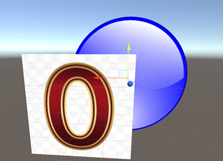

(the blue circle is called mask, and the digital picture is called image)
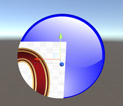
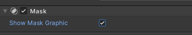
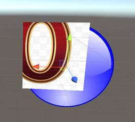
Results after adding a mask component to the "Mask" picture (you can choose whether to hide the mask image):

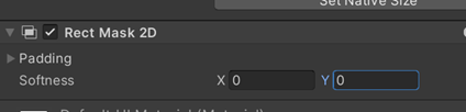
Basic usage of RectMask2D
The usage of RectMask2D is roughly the same as that of mask, but RectMask2D can only cut one rectangular area, and RectMask2D can select edge virtualization

Principle analysis
Principle analysis of Mask
-
Mask will give the Image a special material, which will mark each pixel of the Image and store the marking results in a cache (this cache is called Stencil Buffer)
-
When the child UI is rendering, it will check the mark in the Stencil Buffer. If there is a mark in the currently covered area (that is, the area is within the coverage of the Image), render it, otherwise it will not be rendered
So, what is the Stencil Buffer?
1 StencilBuffer
Simply put, the GPU allocates a 1-byte memory area called StencilBuffer for each pixel, which can be used for the purpose of saving or discarding pixels.
Let's give a simple example to illustrate the essence of this buffer.

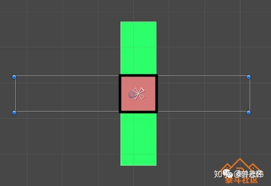
As shown in the figure above, there is a red picture and a green picture in our scene, and their overlapping parts are within the black box. At the beginning of a frame rendering, first, the green picture "draws" the color of each pixel in its coverage on the screen, and then the red picture also draws its own color on the screen, which is the effect in the picture.
In this case, red completely covers green in the overlapping area. Next, we add a Mask component to the green picture. So it became like this:
At this time, the rendering of a frame starts. First, the green picture paints its coverage in green, and sets the stencil buffer value of each pixel to 1. At this time, the stencil buffer distribution of the screen is as follows:

Then it's the turn of the red picture "painting". Before painting red, it will take out the stencil buffer value of this point to judge. Within the range of black box, this value is 1, so it continues to draw red; Outside the black box, the value is 0, so no red is drawn, and finally the effect in the figure is achieved.
Therefore, in essence, stencil buffer exists to realize the communication between multiple "painters". Because gpu is a pipelined job, they can not communicate directly, so they pass messages through this way of sharing data area.
After understanding the principle of stencil, let's take a look at its syntax. The syntax format defined in the unity shader is as follows
(values that can be modified are in brackets, and the rest are keywords):
Stencil
{
	Ref [_Stencil]//Ref represents the value to be compared; 0-255
	Comp [_StencilComp]//Comp represents the comparison method (equal to / not equal to / greater than / less than, etc.);
	Pass [_StencilOp]// Pass/Fail indicates what to do with the stencil buffer when the comparison passes / fails
			// Keep
			// Replace
			// Zero (set to 0)
			// Incrementsaturate (increase)
			// Decrementsaturate (decrease)
	ReadMask [_StencilReadMask]//ReadMask/WriteMask indicates the mask used when getting the value of stencil buffer (that is, some bits can be ignored);
	WriteMask [_StencilWriteMask]
}
Comp are the value of the stencil buffer with the ReadMask and then compare it with the Ref value. If the result is true, perform the Pass operation. Otherwise, perform the Fail operation. Before writing the operation value to the stencil buffer, perform the WriteMask and operation.
2. Source code implementation of mask
After learning about stencil, let's look at the source code implementation of mask
Image and Text will be derived from maskable graphic because image and Text need to be cropped at the same time.
If you want to cut the elements under the Mask node, it needs to occupy a DrawCall, because these elements need a new Shader parameter to render.
As shown in the following code, maskable graphic implements the IMaterialModifier interface, while stencilmaterial Add() is to set the clipping parameters in the Shader.
MaskableGraphic.cs
        public virtual Material GetModifiedMaterial(Material baseMaterial)
        {
            var toUse = baseMaterial;
            if (m_ShouldRecalculateStencil)
            {
                var rootCanvas = MaskUtilities.FindRootSortOverrideCanvas(transform);  //Get template buffer value
                m_StencilValue = maskable ? MaskUtilities.GetStencilDepth(transform, rootCanvas) : 0;
                m_ShouldRecalculateStencil = false;
            }
            // If we use mask, it will generate a mask material,
            Mask maskComponent = GetComponent<Mask>();
            if (m_StencilValue > 0 && (maskComponent == null || !maskComponent.IsActive()))
            {
                //Set the template buffer value, and set the display in this area. If not, it will be cut off
                var maskMat = StencilMaterial.Add(toUse,  // Material baseMat
                    (1 << m_StencilValue) - 1,            // reference value
                    StencilOp.Keep,                       // Do not modify template cache
                    CompareFunction.Equal,                // Equal pass test
                    ColorWriteMask.All,                   // ColorMask
                    (1 << m_StencilValue) - 1,            // Readmask
                    0);                                   //  WriteMas
                StencilMaterial.Remove(m_MaskMaterial);
                //And replace it with a new material
                m_MaskMaterial = maskMat;
                toUse = m_MaskMaterial;
            }
            return toUse;
        }
When the Image object is rebuilt (), the UpdateMaterial() method will obtain the material to be rendered, and judge whether the component of the current object inherits the IMaterialModifier interface. If so, it is bound with the Mask script, and then call the GetModifiedMaterial method to modify the Shader parameters on the material.
Image.cs
   protected virtual void UpdateMaterial()
   {
       if (!IsActive())
           return;
       //Update the material of the new template buffer just replaced
       canvasRenderer.materialCount = 1;
       canvasRenderer.SetMaterial(materialForRendering, 0);
       canvasRenderer.SetTexture(mainTexture);
   }
   public virtual Material materialForRendering
   {
       get
       {
           //Traverse each Mask component in the UI
           var components = ListPool<Component>.Get();
           GetComponents(typeof(IMaterialModifier), components);
           //And update the template buffer material of each Mask component
           var currentMat = material;
           for (var i = 0; i < components.Count; i++)
               currentMat = (components[i] as IMaterialModifier).GetModifiedMaterial(currentMat);
           ListPool<Component>.Release(components);
           //Returns a new material for cutting
           return currentMat;
       }
   }
Because the template buffer can provide the area of the template, that is, the circular image set earlier, the elements will be cut into the center image eventually.
Mask.cs
       /// Stencil calculation time!
       public virtual Material GetModifiedMaterial(Material baseMaterial)
       {
           if (!MaskEnabled())
               return baseMaterial;
           var rootSortCanvas = MaskUtilities.FindRootSortOverrideCanvas(transform);
           var stencilDepth = MaskUtilities.GetStencilDepth(transform, rootSortCanvas);
           // stencil only supports masks with a maximum depth of 8
           if (stencilDepth >= 8)
           {
               Debug.LogError("Attempting to use a stencil mask with depth > 8", gameObject);
               return baseMaterial;
           }
           int desiredStencilBit = 1 << stencilDepth;
           // if we are at the first level...
           // we want to destroy what is there
           if (desiredStencilBit == 1)
           {
               var maskMaterial = StencilMaterial.Add(baseMaterial, 1, StencilOp.Replace, CompareFunction.Always, m_ShowMaskGraphic ? ColorWriteMask.All : 0);
               StencilMaterial.Remove(m_MaskMaterial);
               m_MaskMaterial = maskMaterial;

               var unmaskMaterial = StencilMaterial.Add(baseMaterial, 1, StencilOp.Zero, CompareFunction.Always, 0);
               StencilMaterial.Remove(m_UnmaskMaterial);
               m_UnmaskMaterial = unmaskMaterial;
               graphic.canvasRenderer.popMaterialCount = 1;
               graphic.canvasRenderer.SetPopMaterial(m_UnmaskMaterial, 0);

               return m_MaskMaterial;
           }
           //otherwise we need to be a bit smarter and set some read / write masks
           var maskMaterial2 = StencilMaterial.Add(baseMaterial, desiredStencilBit | (desiredStencilBit - 1), StencilOp.Replace, CompareFunction.Equal, m_ShowMaskGraphic ? ColorWriteMask.All : 0, desiredStencilBit - 1, desiredStencilBit | (desiredStencilBit - 1));
           StencilMaterial.Remove(m_MaskMaterial);
           m_MaskMaterial = maskMaterial2;

           graphic.canvasRenderer.hasPopInstruction = true;
           var unmaskMaterial2 = StencilMaterial.Add(baseMaterial, desiredStencilBit - 1, StencilOp.Replace, CompareFunction.Equal, 0, desiredStencilBit - 1, desiredStencilBit | (desiredStencilBit - 1));
           StencilMaterial.Remove(m_UnmaskMaterial);
           m_UnmaskMaterial = unmaskMaterial2;
           graphic.canvasRenderer.popMaterialCount = 1;
           graphic.canvasRenderer.SetPopMaterial(m_UnmaskMaterial, 0);

           return m_MaskMaterial;
       }
The Mask component calls the template shader to build its own shader, so it uses the template method in real-time rendering to cut the parts that do not need to be displayed, and all child nodes of the Mask component will be cut.
We can say that Mask is the cutting done in GPU, and the method used is the template method in shader.
Principle analysis of RectMask2D
The workflow of RectMask2D is roughly as follows:
① C# layer: find the intersection of all RectMask2D coverage areas in the parent object (FindCullAndClipWorldRect)
② C# layer: all sub object components that inherit MaskGraphic call the method to set the clipping area (SetClipRect) and pass it to the Shader
③ Shader layer: rectangular area received_ ClipRect: determine whether the pixel is in the rectangular area in the slice shader. If it is not, the transparency is set to 0 (unityget2dlipping)
④ Shader layer: discard elements with alpha less than 0.001 (clip (color.a - 0.001))
CanvasUpdateRegistry.cs
        protected CanvasUpdateRegistry()
        {
            Canvas.willRenderCanvases += PerformUpdate;
        }
        private void PerformUpdate()
        {
            //... slightly
            // Start cutting Mask2D
            ClipperRegistry.instance.Cull();
            //... slightly
        }
ClipperRegistry.cs
        public void Cull()
        {
            for (var i = 0; i < m_Clippers.Count; ++i)
            {
                m_Clippers[i].PerformClipping();
            }
        }
RectMask2D will register the current component with clipperregistry in the OnEnable() method Register(this);
So click clipperregistry instance. Cull(); Method, you can traverse all Mask2D components and call their PerformClipping() method.
For the PerformClipping() method, you need to find all UI elements that need to be trimmed, because Image and Text inherit the IClippable interface, and will eventually call cut ().
RectMask2D.cs
    protected override void OnEnable()
    {
        //Register the current RectMask2D cutting object to ensure that cutting can be performed during the next Rebuild.
        base.OnEnable();
        m_ShouldRecalculateClipRects = true;
        ClipperRegistry.Register(this);
        MaskUtilities.Notify2DMaskStateChanged(this);
    }
        public virtual void PerformClipping()
        {
            //... slightly
            bool validRect = true;
            Rect clipRect = Clipping.FindCullAndClipWorldRect(m_Clippers, out validRect);
            bool clipRectChanged = clipRect != m_LastClipRectCanvasSpace;
            if (clipRectChanged || m_ForceClip)
            {
                foreach (IClippable clipTarget in m_ClipTargets)
                    //Transfer the cutting area to the Shader of each UI element [highlight!!!]
                    clipTarget.SetClipRect(clipRect, validRect);
                m_LastClipRectCanvasSpace = clipRect;
                m_LastValidClipRect = validRect;
            }
            foreach (IClippable clipTarget in m_ClipTargets)
            {
                var maskable = clipTarget as MaskableGraphic;
                if (maskable != null && !maskable.canvasRenderer.hasMoved && !clipRectChanged)
                    continue;
                // Call all the curl methods that inherit IClippable
                clipTarget.Cull(m_LastClipRectCanvasSpace, m_LastValidClipRect);
            }
        }
MaskableGraphic.cs
        public virtual void Cull(Rect clipRect, bool validRect)
        {
            var cull = !validRect || !clipRect.Overlaps(rootCanvasRect, true);
            UpdateCull(cull);
        }
        private void UpdateCull(bool cull)
        {
            var cullingChanged = canvasRenderer.cull != cull;
            canvasRenderer.cull = cull;
            if (cullingChanged)
            {
                UISystemProfilerApi.AddMarker("MaskableGraphic.cullingChanged", this);
                m_OnCullStateChanged.Invoke(cull);
                SetVerticesDirty();
            }
        }
Performance differentiation
The Mask component needs to rely on an Image component, and the clipping area is the size of the Image.
The mask will draw all at the beginning and end (after the children under the first = mask node and the tail = mask node have finished traversing). If the batch conditions are met among multiple masks, the two drawcall s can correspond to the batch (the first of mask1 and the first of mask2; the tail of mask1 and the tail of mask2. The first and tail cannot be combined)
UI nodes in a Mask and UI nodes other than a Mask cannot be combined. However, if the UI nodes in multiple masks meet the batch conditions, they can be combined.
Specifically:
Create a new scene. The default drawcall is 2;
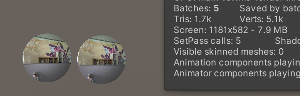
Now add a mask,
drawcall+3, Mask leads to two drawcalls (the first and third, one head and one tail), and the child node Image under Mask leads to one drawcall (in the middle)
Take another look at RectMask2D
Only one new child node Image drawcall is added, but RectMask2D will not cause drawcall
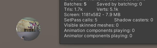
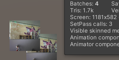
In this case, add a mask without overlapping:
Or five drawcall s, no change
Unity merged the meshes of 2 masks and 3 drawcall s, which are [2 Mask headers], [2 images] and [2 Mask tails]
It can be seen here that masks can be merged without adding additional drawcall
And if you put it together,
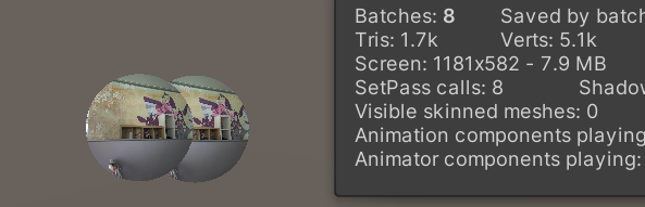
**This is because Unity's batch needs the same depth, the same material and the same atlas. If it overlaps, the depth will be different. The six drawcall s are Mask head, Mask Image, Mask tail, Mask(1) head, Mask(1) Image and Mask(1) tail
Mask summary:
1. Multiple masks can be combined (head and head combined batch, sub object and sub object combined batch, tail and tail combined batch), which needs to be at the same rendering level (depth), the same material and the same atlas
2. The internal and external of mask cannot be approved together
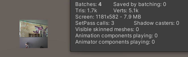
Try RectMask2D again
Copy rectmask 2D and position it**
Drawcall is 4. Because RectMask2D itself will not cause drawcall, batch cooperation between RectMask2D cannot be carried out
RectMask2D summary:
1.RectMask2D itself does not generate drawcall
2. Sub objects of different RectMask2D cannot be grouped
Comparative test
Here is a simple comparison test I did on the mobile phone:

It can be roughly seen that when the image is large and the cpu task is heavy, the mask will have a significant impact on the performance, and when the number of images is large, the mask is slightly better than RectMask2D
Project link: https://git.woa.com/jnjnjnzhang/MaskVsRectmask2d
Note: about 60 batches are included in the test scenario. Add the same 20 masks to each mask test. For scenes with a small number of images, one image is hung under each mask. When the area is large, the mask size remains the same, and the image side length is enlarged by 1000 times. When the number is large, the same 100 images are hung under each mask. When the bottleneck is drawcall, each object only has simple rendering, and scripts requiring complex operations are mounted on the object. When the bottleneck is gpu, remove the script and mount post-processing rendering in the scene to improve the gpu load.
Reference articles
https://zhuanlan.zhihu.com/p/136505882