Computer network -- Cisco Packet Tracer experiment
This experiment is based on Chess song teaching network complete
There are 15 experiments in this part, which need to be completed by Cisco packet tracker software.
Please first understand the concepts of VLSM, CIDR, RIP, OSPF, VLAN, STP, NAT and DHCP to enable network planning and configuration.
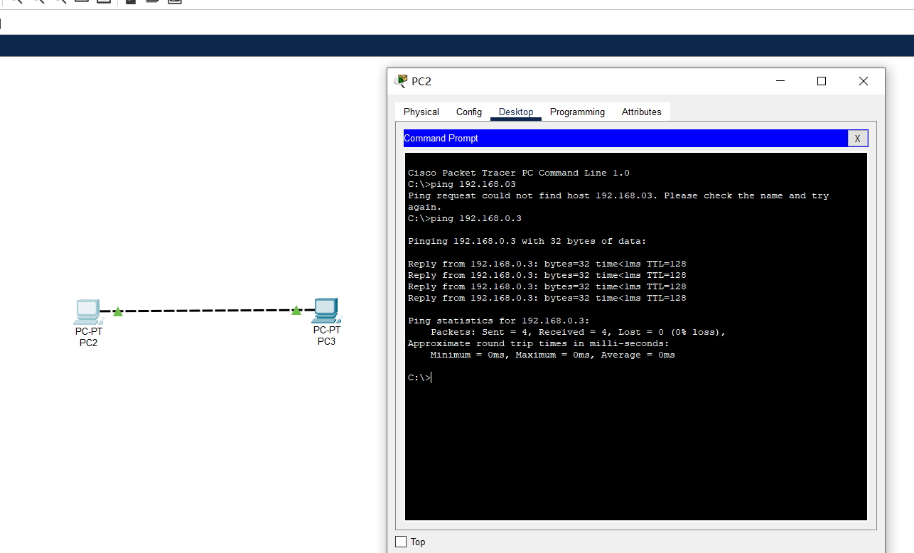
1, Connect two PC s directly to build LAN
- Connect two PC s directly to form a network. Note: cross wires are required for direct connection.
- For the basic network configuration of two PC s, you only need to configure the IP address, and then ping each other successfully.
2, Building LAN with switches
Build a LAN with the following topology:
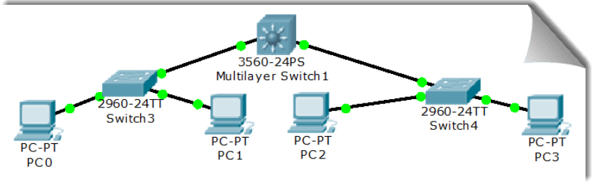
The basic network configuration of each PC is shown in the following table:
| machine name | IP | Subnet mask |
|---|---|---|
| PC0 | 192.168.1.1 | 255.255.255.0 |
| PC1 | 192.168.1.2 | 255.255.255.0 |
| PC2 | 192.168.2.1 | 255.255.255.0 |
| PC3 | 192.168.2.2 | 255.255.255.0 |
✎ problem
Can PC0 ping PC1, PC2 and PC3? Can PC3 ping PC0, PC1 and PC2? Why? Connect 4 pcs
The masks are changed to 255.255.0.0. Can they ping each other? Why? Does the network connected by layer-2 switch need to be configured with a gateway? Why?
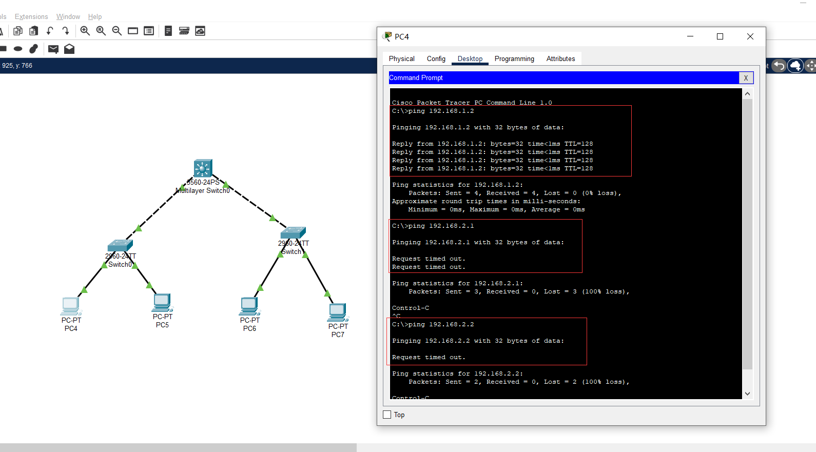
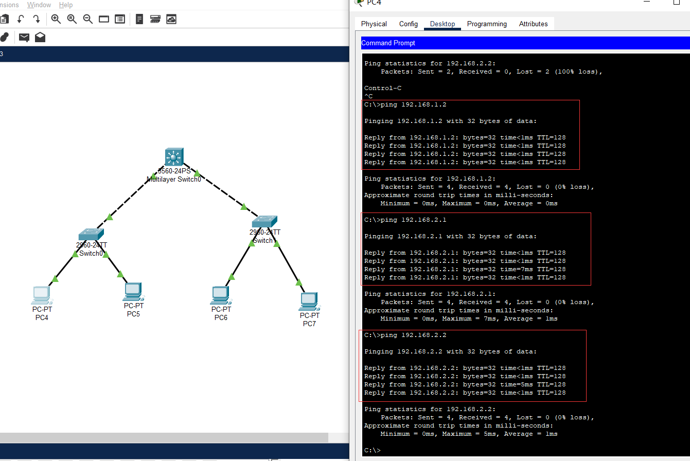
- Through experiments, it is found that PC0 can ping PC1, but cannot Ping PC2 and PC3.
- PC3 can only ping PC2, but not PC0 and PC1. Because PC3 is not in the same subnet as PC0 and PC1, it cannot ping.
- After the masks of the four PC s are changed to 255.255.0.0, they can be ping ed because their IP addresses and subnet masks are 192.168.0.0, which are under the same subnet.
- need. The gateway is used to establish transmission connections between two networks, so that hosts on different networks can establish cascaded, point-to-point transmission connections across multiple networks.
3, Switch interface address list
Layer 2 switch is a plug and play multi interface device. It has three processing methods for received frames: broadcasting, forwarding and discarding (please find out when and what operations). Then, to forward successfully, the switch must have an interface address list, i.e. MAC table, which is automatically obtained by the switch through learning!
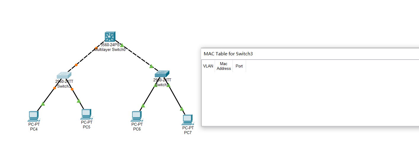
Still build the topology shown in the figure above, and configure the IP of each computer in the same subnet. Use the magnifying glass in the toolbar to click a switch, such as Switch3 on the left, and select MAC Table. You can see that the MAC Table of the original switch is empty, that is, it doesn't know how to forward frames (how will it handle it?), After accessing (ping) PC1 with PC0, check the MAC Table of the switch. Now there are corresponding records. Please think about how to get them. With the increase of network communication, each switch will generate its own complete MAC Table. At this time, the switching speed of the switch is the fastest!
MAC table before ping:
MAC table after ping:
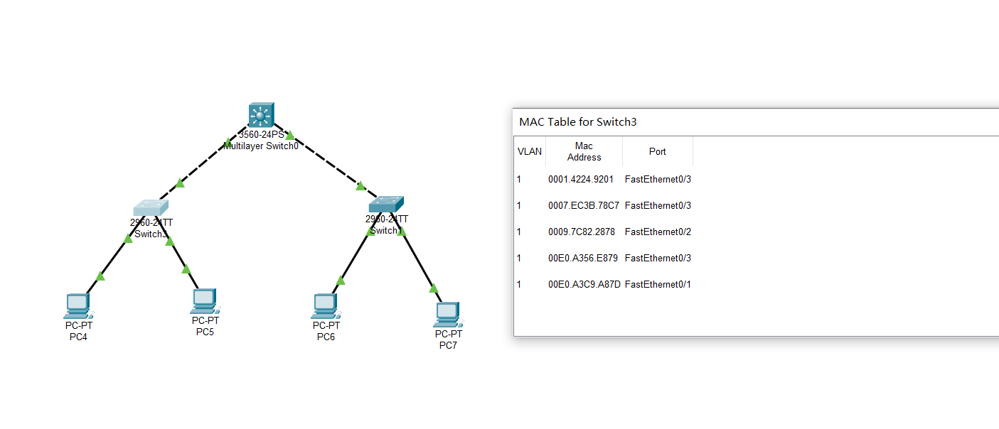
Thinking: at the beginning of the switch, the MAC address table is empty, and no host knows whose MAC address. When host A wants to communicate with host B, it will first send an ARP broadcast to know the MAC address of host B. the switch receives the broadcast packet, corresponds the MAC of host A to the MAC address table, matches it with the incoming port, and then forwards the broadcast, Host B responds to this broadcast packet and tells host A its own MAC address. The switch also records that the MAC address of host B corresponds to the entry port, and the MAC address table is established.
📬 Secret script
You can also use CPT's Simulation mode, that is, Simulation mode, to further see this process!
4, Spanning Tree Protocol
The switch will broadcast when the destination address is unknown or the broadcast frame is received. If there is a loop / loop between switches, a broadcast cycle storm will occur, which will seriously affect the network performance.
The STP protocol running in the switch can avoid the broadcast cycle storm between switches.
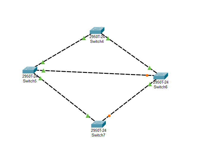
Using only switches, build the following topology:
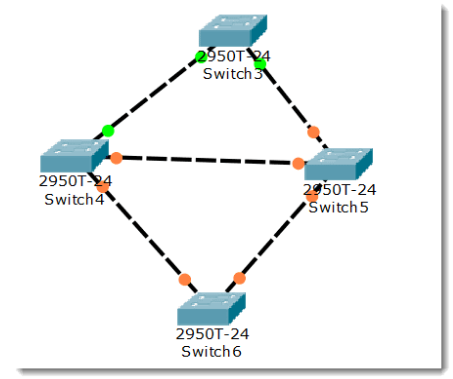
This is the initial state. We can see that there is a loop between switches, which will cause the cyclic transmission of broadcast frames, that is, a broadcast storm, which will seriously affect the network performance.
Then, the switch will automatically block the redundant lines through the spanning tree protocol (STP) to form a spanning tree with a unique path tree with Switch4 as the root (which root switch has relevant policies)!
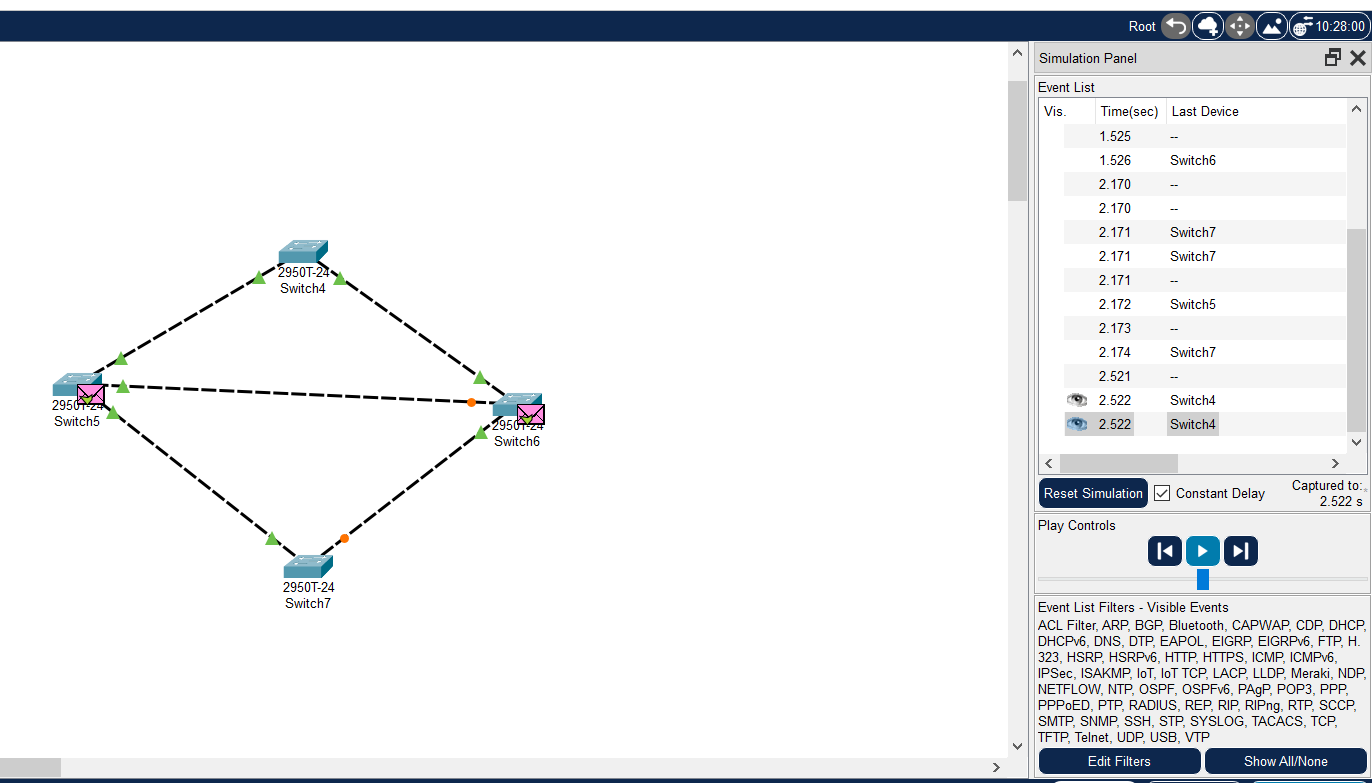
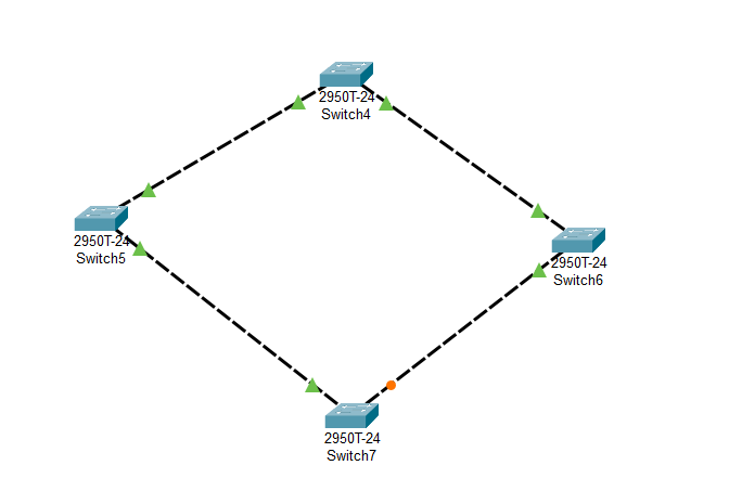
After a period of time, with the STP protocol successfully building the spanning tree, the two interfaces of Switch5 are physically connected, but logically impassable. They are in Blocking state (Orange), as shown in the following figure:
During network operation, if there is a problem with the physical connection between Switch4 and Switch5 at some time (cut off the connection between Switch4 and Switch5), the spanning tree will change automatically. The previous Blocking interface above Switch5 is now active (green), but the interface below Switch5 is still Blocking (Orange). As shown in the figure below:
🗣 be careful
The STP protocol of the switch, the spanning tree protocol, always automatically ensures that there will be no loop between switches, resulting in a broadcast storm.
5, Preliminary router configuration
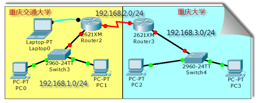
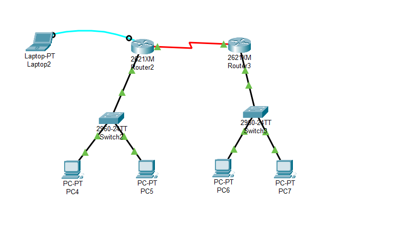
We simulate the connection between Chongqing Jiaotong University and Chongqing University, and construct the following topology:
Description I
Jiaotong University and Chongqing University are obviously two different subnets. The communication between different subnets needs to pass through the router.
There is at least one subnet under each interface of the router. In the figure, we simply plan three subnets:
- The router on the left belongs to Jiaotong University. The switch is used to connect the network of Jiaotong University, and the assigned network number is 192.168.1.0/24. The router interface is also the gateway of Jiaotong University network, and the assigned IP is 192.168.1.1
- The router on the right belongs to Chongqing University. The switch is used to connect the network of Chongqing University. The assigned network number is 192.168.3.0/24. The router interface is also the gateway of Chongqing University network. The assigned IP is 192.168.3.1
- The two routers are connected by WAN interface, which is also a subnet. The assigned network number is 192.168.2.0/24

Note II
In reality, the connection between Jiaotong University and Chongqing University is remote. The connection is either through the optical fiber interface of the router or through the WAN interface, the so-called serial port (as shown in the topology diagram). Generally, it is not connected through twisted pair (why?).
Because the transmission distance of twisted pair is limited, the signal needs to be amplified again every 100m, and the deployment cost is high.
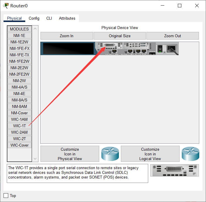
Let's take the WAN port connection through the router as an example to make relevant configuration. Please note: the router we selected does not have a WAN module (WIC-1T, etc.) by default. You need to turn off the router, add it, and then turn it on.
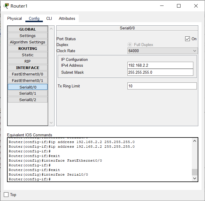
Note III
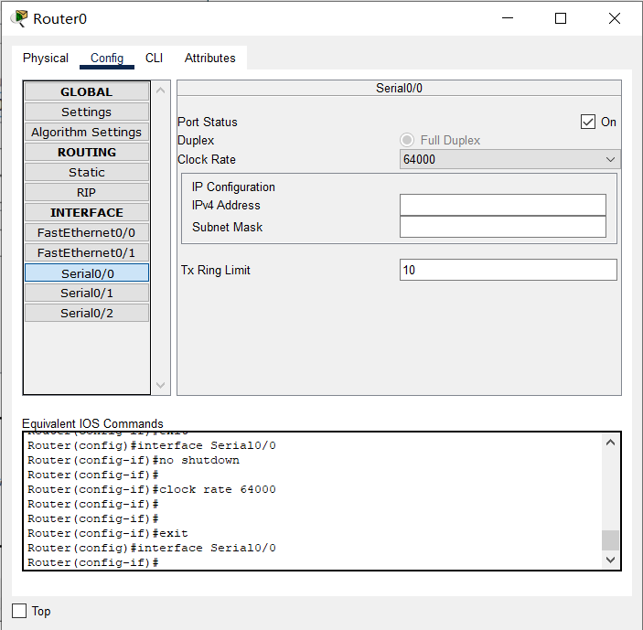
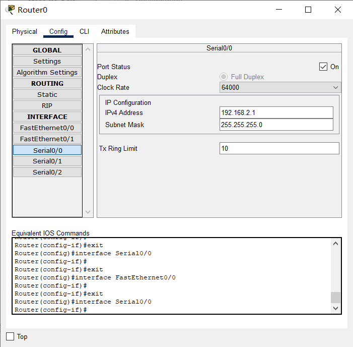
In the simulated WAN connection, pay attention to the DCE and DTE terminals (there is a prompt on the line when connecting, and the DCE terminal with a clock flag. Please refer to relevant materials for the concepts of DCE and DTE), Clock frequency 64000 shall be configured at DCE end
Note IV
The router has a variety of command line configuration modes, and each mode corresponds to different prompts and corresponding permissions.
Please pay attention to entering configuration related commands in the correct mode.
- User mode: user mode
- Privileged mode: privileged mode
- Global configuration mode: global configuration mode
- Interface mode: interface configuration mode
- Subinterface mode: subinterface configuration mode
Note V
In reality, it is obvious that the new router cannot be configured remotely. We must connect with the console interface of the router through the serial port of the notebook and make the initial configuration (note that the bit rate is set to 9600) before we can configure remotely through the network. This is also the intention of the notebook connection drawn on the upper left of the figure above.
Note VI
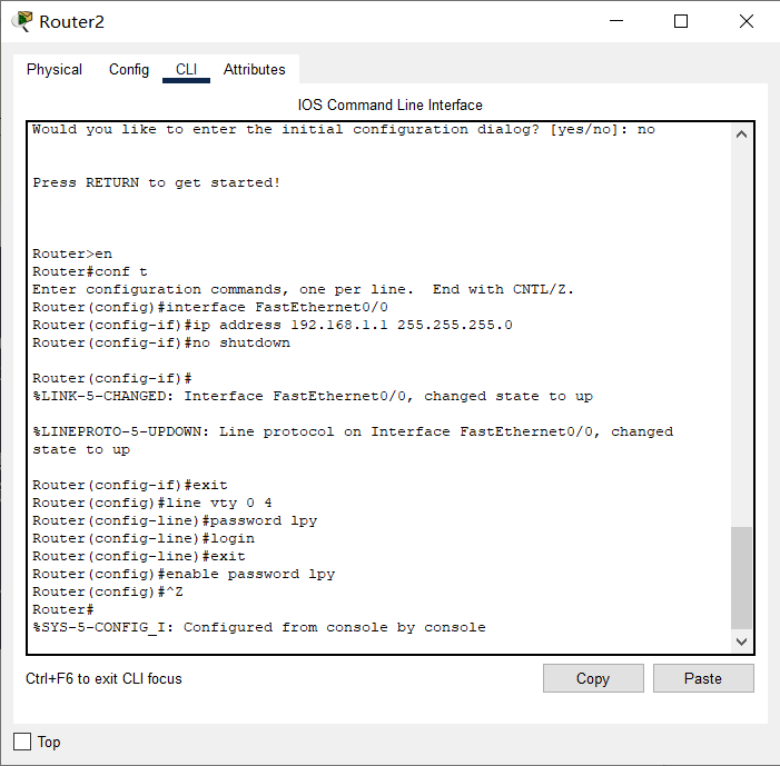
In the CLI interface of the router, you can see that after the router is started successfully, because there is NO configuration, you will be prompted whether to enter the initial configuration dialog, Select NO because there are many steps
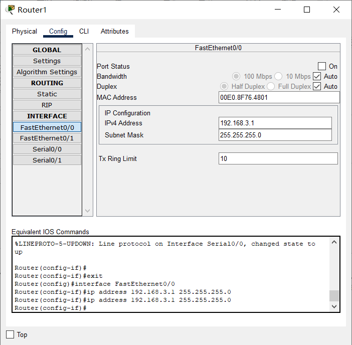
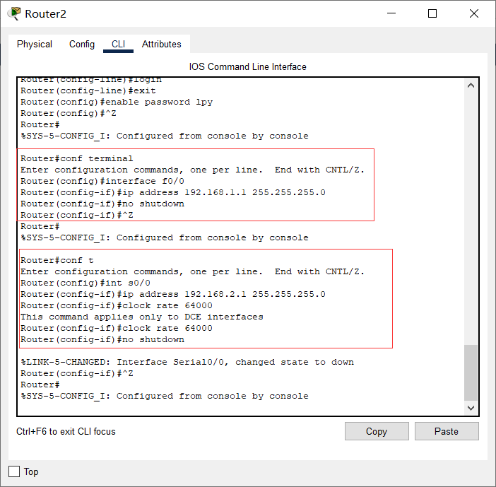
The preliminary configuration of Jiaotong University router can be as follows:
🗣 be careful
In our experiment, the following configurations are not necessary, but in reality, for security, the following login and privileged password configurations are necessary, otherwise everyone can operate your router or switch!
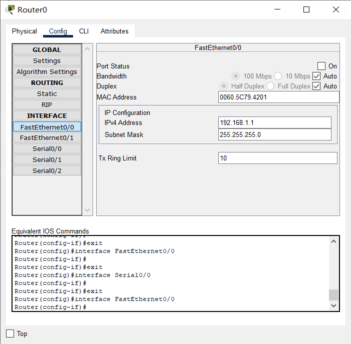
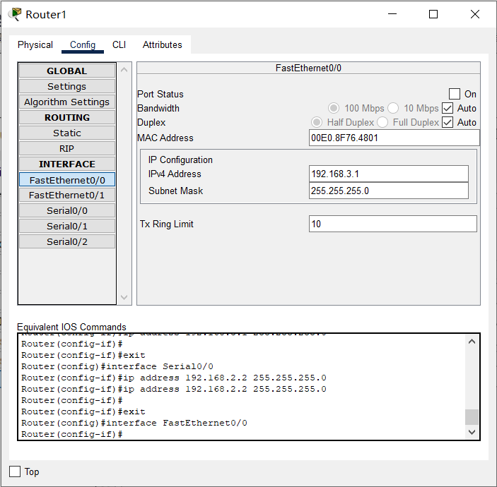
The router interface configuration data in the topology diagram is as follows:
| Interface name | IP | Subnet mask |
|---|---|---|
| Router2 Ethernet port of Jiaotong University | 192.168.1.1 | 255.255.255.0 |
| Router2 WAN port of Jiaotong University | 192.168.2.1 | 255.255.255.0 |
| Router3 Ethernet port of Chongqing University | 192.168.3.1 | 255.255.255.0 |
| Router3 WAN port of Chongqing University | 192.168.2.2 | 255.255.255.0 |
The PC configuration data in the topology diagram is as follows:
| Node name | IP | Subnet mask | gateway |
|---|---|---|---|
| Router2 Ethernet port of Jiaotong University | 192.168.1.1 | 255.255.255.0 | 192.168.1.1 |
| Router2 WAN port of Jiaotong University | 192.168.2.1 | 255.255.255.0 | 192.168.1.1 |
| Router3 Ethernet port of Chongqing University | 192.168.3.1 | 255.255.255.0 | 192.168.1.1 |
| Router3 WAN port of Chongqing University | 192.168.2.2 | 255.255.255.0 | 192.168.1.1 |
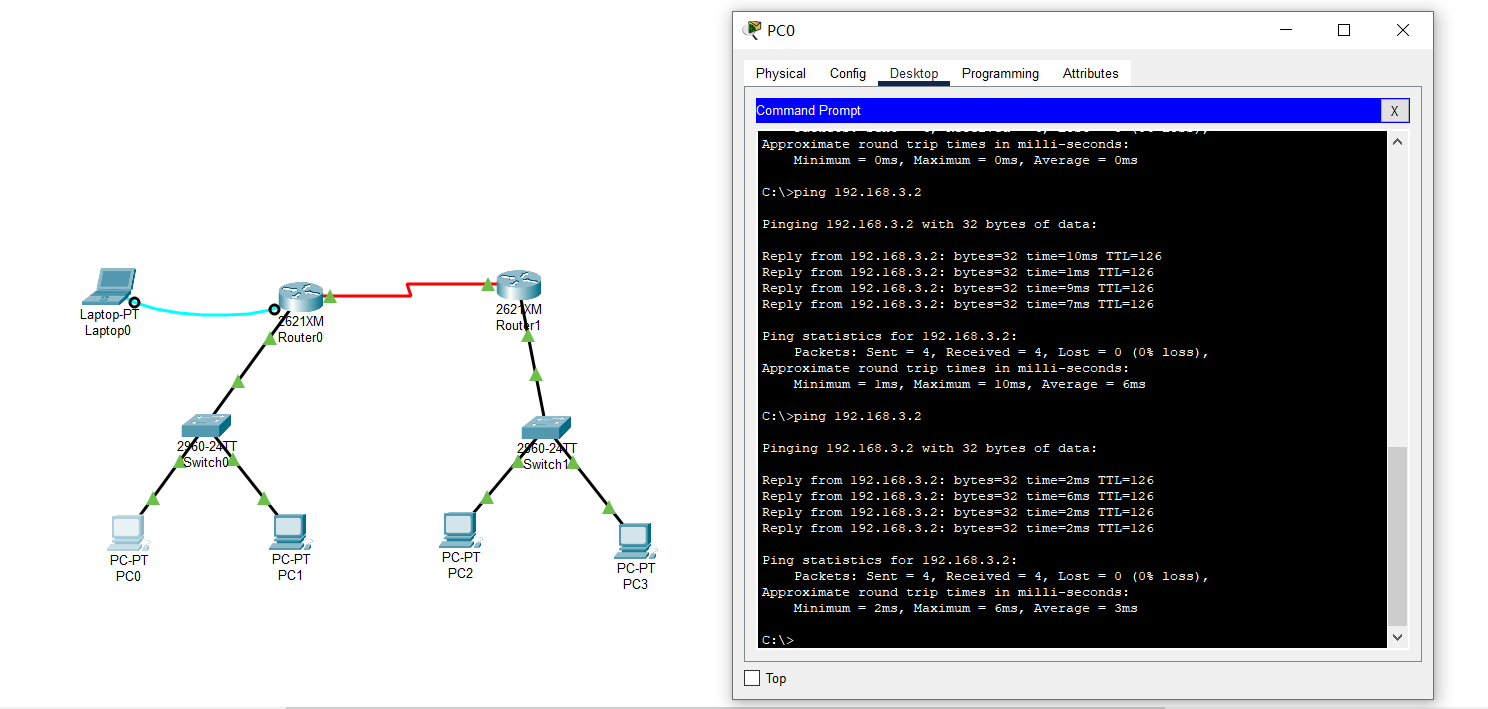
The basic configuration of Jiaotong University router is as follows:
The basic configuration of Chongqing University router is as follows:
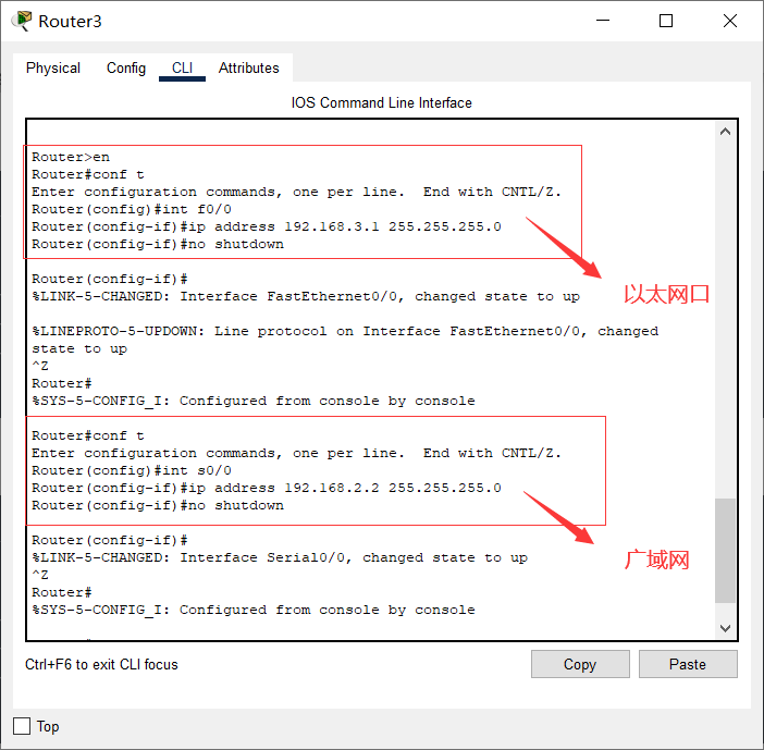
You can see that the configuration has been successful.
At this point, the basic configuration of the router is completed. Continue to configure each PC according to the PC configuration table above.
✎ problem
At present, PCs and gateways in Jiaotong University can ping each other, and Chongqing University is similar. But you can't Ping major from the PC of Jiaotong University
PC, and vice versa, that is, it cannot cross subnets. Why?
A: static routing is not configured, and the routing table has not been built
6, Static routing
Static routing is a non adaptive routing protocol, which is manually configured by network managers and cannot be changed according to the change of network topology. Therefore, static routing is simple and efficient, and is suitable for networks with very simple structure.
In the current simple topology, we can use static routing, that is, we can directly tell the router how to get to a network.
When the basic configuration of the above router is successful, use the following command to configure the static routing protocol:
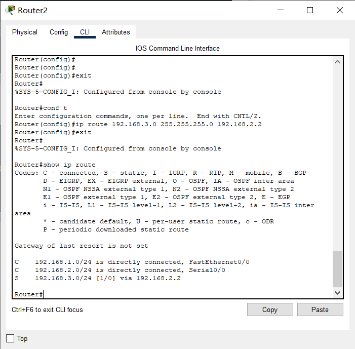
Static routing configuration of Jiaotong University Router:
Router>en   // Enter privileged mode from normal mode
Router#conf t / / enter global configuration mode
Router(config)#ip route 192.168.3.0 255.255.255.0 192.168.2.2 / / tell the router of Jiaotong University that the next hop of the network to 192.168.3.0 is 192.168.2.2
Router(config)#Exit / / exit to privileged mode
Router#show ip route / / view the route table
Chongqing University router static routing configuration:
Router>en   // Enter privileged mode from normal mode
Router#conf t / / enter global configuration mode
Router(config)#ip route 192.168.1.0 255.255.255.0 192.168.2.1 / / tell the Chongqing University router that the next hop to 192.168.1.0 is 192.168.2.1
Router(config)#Exit / / exit to privileged mode
Router#show ip route / / view the route table
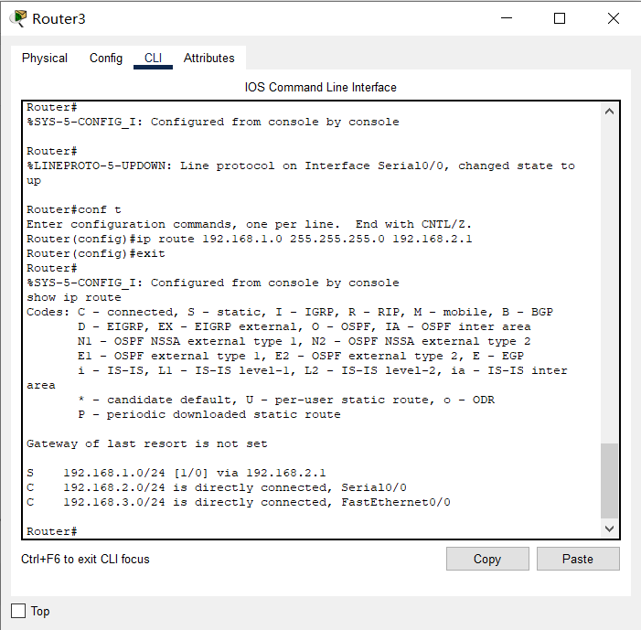
Check the routing table and you can see a route marked S, which means Static.
So far, these PC s can ping each other!
Note: our topology only simulates 3 networks. In reality, the number of networks connected by the router is very large. We also need to configure a default route, otherwise other networks cannot reach! Of course, our topology can be ignored.
Router (config) #ip route 0.0.0.0 0.0.0... / / forward all to... *. By default* This IP
7, Dynamic routing RIP
Dynamic routing protocol adopts adaptive routing algorithm, which can re optimize the computer routing according to the change of network topology.
The full name of RIP is Routing Information Protocol, which is the representative of distance vector routing (although it is eliminated at present, it can be used as our learning object). Using rip protocol only needs to tell the router which networks are directly connected, and then rip automatically constructs the routing table according to the algorithm.
Because the network we simulated is very simple, we can't use static and dynamic routes at the same time, otherwise we can't see the effect. Therefore, we need to clear the static routes just configured.
Clear static routing configuration:
1. Turn off the router directly. It is equivalent to not saving any configuration, and then reconfiguring IP and other parameters of each interface according to the previous basic configuration (this method is recommended, and you can get familiar with the interface configuration command again);
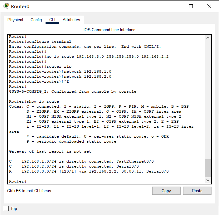
2. Use the no command to clear the static route. In the global configuration mode, Jiaotong University router uses no ip route 192.168.3.0 255.255.255.0 192.168.2.2, and Chongqing University router uses no ip route 192.168.1.0 255.255.255.0 192.168.2.1. It is equivalent to using the no command to cancel the static routing command just configured.
RIP routing configuration of Jiaotong University Router:
Router>en   // Enter privileged mode from normal mode
Router#conf t / / enter global configuration mode
Router(config)#router rip / / enable the RIP routing protocol. Note the router command
Router(config-router)#Network 192.168.1.0 / / network 192.168.1.0 is directly connected to me
Router(config-router)#Network 192.168.2.0 / / network 192.168.2.0 is directly connected to me
Router(config-router)#^z / / directly retreat to privileged mode
Router#show ip route / / view the route table
RIP routing configuration of Chongqing University Router:
Router>en   // Enter privileged mode from normal mode
Router#conf t / / enter global configuration mode
Router(config)#router rip / / enable the RIP routing protocol. Note the router command
Router(config-router)#Network 192.168.3.0 / / network 192.168.3.0 is directly connected to me
Router(config-router)#Network 192.168.2.0 / / network 192.168.2.0 is directly connected to me
Router(config-router)#^z / / directly retreat to privileged mode
Router#show ip route / / view the route table
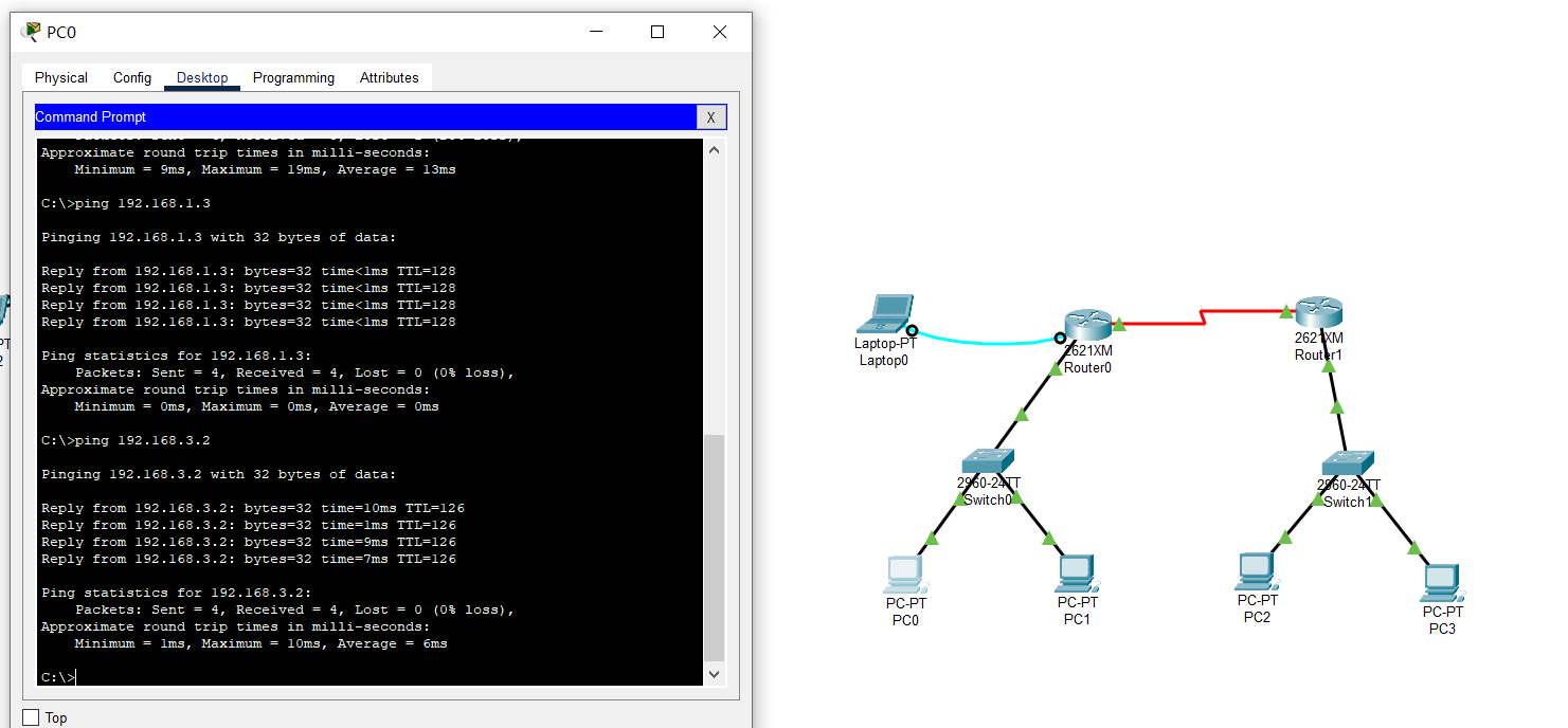
Looking at the routing table, you can see a route marked R, which means RIP.
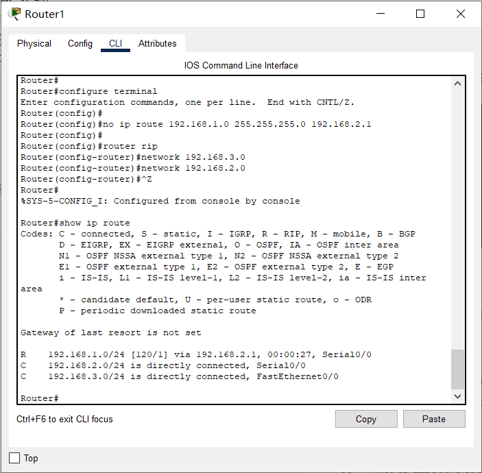
So far, these PC s can ping each other!
📬 Secret script
You can use debug ip rip to start RIP diagnosis in privileged mode. At this time, you will see the distance vector information constantly sent between routers to judge whether the network state has changed, so as to update the routing table. This command will constantly display relevant information and disturb our input. You can use no debug ip rip to turn off RIP diagnosis
8, Dynamic routing OSPF
OSPF (Open Shortest Path First) is an internal gateway protocol (IGP) used to make routing decisions in a single Autonomous System (AS). OSPF has better performance than RIP and is a widely used routing protocol for intra domain routing.
Similarly, we need to clear the RIP route just configured.
Clear RIP routing configuration:
1. Turn off the router directly. It is equivalent to that no configuration is saved, and then each interface reconfigures IP and other parameters according to the previous basic configuration
2. Use the no command to clear the RIP route. In the global configuration mode, all routers use the: no router rip command to clear
OSPF routing configuration of Jiaotong University Router:
Router>en   // Enter privileged mode from normal mode
Router#conf t / / enter global configuration mode
Router(config)#router ospf 1 / / enable OSPF routing protocol. The process number is 1 (you can ignore the concept of process number temporarily)
Router(config-router)#Network 192.168.1.0 0.0.255 area 0 / / all hosts belonging to the 192.168.1.0/24 network in autonomous domain 0 (reverse mask) participate in OSPF
Router(config-router)#Network 192.168.2.0 0.0.255 area 0 / / all hosts belonging to the 192.168.2.0/24 network in autonomous domain 0 (reverse mask) participate in OSPF
Router(config-router)#^z / / directly retreat to privileged mode
Router#show ip route / / view the route table
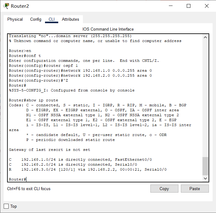
There is no path O here
OSPF routing configuration of Chongqing University Router:
Router>en   // Enter privileged mode from normal mode
Router#conf t / / enter global configuration mode
Router(config)#router ospf 1 / / enable OSPF routing protocol. The process number is 1
Router(config-router)#Network 192.168.3.0 0.0.255 area 0 / / all hosts belonging to the 192.168.3.0/24 network in autonomous domain 0 (reverse mask) participate in OSPF
Router(config-router)#Network 192.168.2.0 0.0.255 area 0 / / all hosts belonging to the 192.168.2.0/24 network in autonomous domain 0 (reverse mask) participate in OSPF
Router(config-router)#^z / / directly retreat to privileged mode
Router#show ip route / / view the route table
Looking at the routing table, you can see a route marked O, which means OSPF.
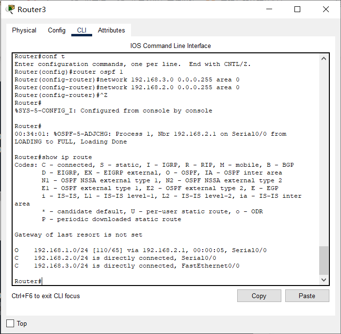
So far, these PC s can ping each other!
📬 Secret script
You can use debug ip ospf events in privileged mode to enable OSPF diagnostics (no debug ip ospf events)
Turn off diagnosis), and you can see the Hello information sent between routers to diagnose whether the current link has changed for route adjustment (event trigger rather than regular update!).
🗣 Reverse mask
Our common subnet mask is the so-called forward mask, which is represented by continuous 1 and 0, where 1 indicates that accurate matching is required and 0 does not need to be, so as to obtain the network number.
Similarly, the reverse mask is also represented by continuous 1 and 0, but on the contrary, where 0 means that exact matching is required, and 1 does not need to, so as to obtain the relevant IP, which is mainly used for OSPF
Yes.
There is also a wildcard mask, which also adopts rules similar to the reverse mask. It is mainly used in the Access Control List ACL.
9, Port based network address translation PAT
Network Address Translation (NAT) is widely used by various Internet service providers, namely ISP s, in their networks, including WiFi networks. The reason is very simple. NAT not only perfectly solves the problem of insufficient lP address, but also can effectively avoid attacks from outside the network and hide and protect computers inside the network.
NAT can be implemented in three ways:
- Static conversion: Static NAT
- Dynamic conversion: Dynamic NAT
- Port multiplexing: OverLoad
Port multiplexing is the most used and flexible. OverLoad refers to not only changing the source IP address of data packets sent to the Internet, but also changing its source port, that is, Port Address Translation (PAT).
Using port multiplexing, all hosts in the internal network can share a legal external IP address to access the Internet, so as to save IP address resources to the greatest extent. At the same time, it can hide all hosts inside the network to effectively avoid attacks from the Internet. Therefore, port multiplexing is the most widely used method in the network.
We still use the topology of Chongqing Jiaotong University and Chongqing University for PAT experiment. We need to ensure that the routing of the two schools has been configured successfully. Whether static routing or dynamic routing is used, we give a complete configuration process as follows: set the routers of the two schools to use OSPF protocol, simulate Jiaotong University to use internal IP address (192.168.1.0 / 24), and simulate Chongqing University to use external IP address (8.8.8.0 / 24), The external IP address (202.202.240.0 / 24) is used between the two routers to implement PAT at the exit of Jiaotong University, that is, the WAN port.
The PC configuration data in the topology diagram is as follows:
| Node name | IP | Subnet mask | gateway |
|---|---|---|---|
| Jiaotong University PC0 | 192.168.1.2 | 255.255.255.0 | 192.168.1.1 |
| Jiaotong University PC1 | 192.168.1.3 | 255.255.255.0 | 192.168.1.1 |
| Chongqing University PC2 | 8.8.8.2 | 255.255.255.0 | 8.8.8.1 |
| Chongqing University PC3 | 8.8.8.3 | 255.255.255.0 | 8.8.8.1 |
🗣 Please note that the network configuration of the two pcs of Chongqing University has changed. We simulate it as an external / public IP address!
The router interface configuration data in the topology diagram is as follows:
| Interface name | IP | Subnet mask |
|---|---|---|
| Router2 Ethernet port of Jiaotong University | 192.168.1.1 | 255.255.255.0 |
| Router2 WAN port of Jiaotong University | 202.202.240.1 | 255.255.255.0 |
| Router3 Ethernet port of Chongqing University | 8.8.8.1 | 255.255.255.0 |
| Router3 WAN port of Chongqing University | 202.202.240.2 | 255.255.255.0 |
🗣 Please note that the network configuration of the two interfaces of Chongqing University router and the WAN port of Jiaotong University has changed, then configure OSPF routing, and finally implement PAT at the WAN port of Jiaotong University router!
The router interface configuration of Jiaotong University is as follows:
Ethernet port:
Router>en   // Enter privileged mode from normal mode
Router#conf t / / enter global configuration mode
Router(config)#int f0/0 / / enter the configuration Ethernet port mode
Router(config-if)#ip address 192.168.1.1 255.255.255.0 / / configure IP address
Router(config-if)#no shutdown / / activate the interface
WAN port:
Router>en   // Enter privileged mode from normal mode
Router#conf t / / enter global configuration mode
Router(config)#int s0/0 / / enter the WAN port configuration mode
Router(config-if)#ip address 202.202.240.1 255.255.255.0 / / configure IP address
Router(config-if)#clock rate 64000 / / it is the DCE terminal. Configure the clock frequency
Router(config-if)#no shutdown / / activate the interface
The router interface configuration of Chongqing University is as follows:
Ethernet port:
Router>en   // Enter privileged mode from normal mode
Router#conf t / / enter global configuration mode
Router(config)#int f0/0 / / enter the configuration Ethernet port mode
Router(config-if)#ip address 8.8.8.1 255.255.255.0 / / configure IP address
Router(config-if)#no shutdown / / activate the interface
WAN port:
Router>en   // Enter privileged mode from normal mode
Router#conf t / / enter global configuration mode
Router(config)#int s0/0 / / enter the WAN port configuration mode
Router(config-if)#ip address 202.202.240.2 255.255.255.0 / / configure IP address
Router(config-if)#no shutdown / / activate the interface
OSPF routing configuration of Jiaotong University Router:
Router>en   // Enter privileged mode from normal mode
Router#conf t / / enter global configuration mode
Router(config)#router ospf 1 / / enable OSPF routing protocol. The process number is 1 (you can ignore the concept of process number temporarily)
Router(config-router)#Network 192.168.1.0 0.0.255 area 0 / / all hosts belonging to the 192.168.1.0/24 network in autonomous domain 0 (reverse mask) participate in OSPF
Router(config-router)#Network 202.202.240.0 0.0.255 area 0 / / all hosts belonging to the 202.202.240.0/24 network in autonomous domain 0 (reverse mask) participate in OSPF
OSPF routing configuration of Chongqing University Router:
Router>en   // Enter privileged mode from normal mode
Router#conf t / / enter global configuration mode
Router(config)#router ospf 1 / / enable OSPF routing protocol. The process number is 1
Router(config-router)#Network 202.202.240.0 0.0.255 area 0 / / all hosts belonging to the 202.202.240.0/24 network in autonomous domain 0 (reverse mask) participate in OSPF
Router(config-router)#Network 8.8.8.0 0.0.255 area 0 / / all hosts belonging to the 8.8.8.0/24 network in autonomous domain 0 (reverse mask) participate in OSPF
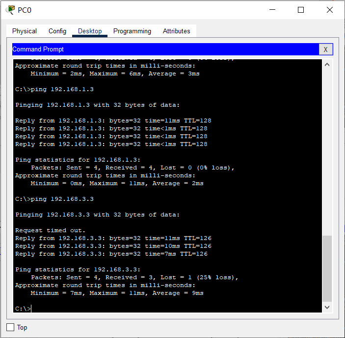
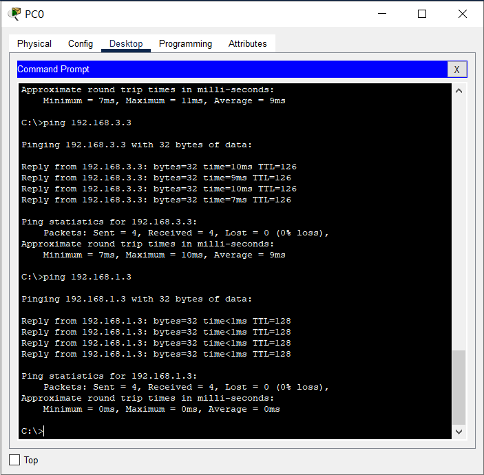
At this point, these PCs can ping each other! For example, using PC0 (192.168.1.2) to Ping PC2 (8.8.8.2) of Chongqing University within Jiaotong University should be successful.
Next, we will look at the routers of Chongqing University as the backbone routers in the Internet, so these routers will not forward packets with internal / private IP addresses (directly discarded). We simulate the process of packet loss by implementing access control ACL on Chongqing University router, that is, discarding packets from Jiaotong University (private IP address).
Packet loss configuration of Chongqing University Router:
Router>en   // Enter privileged mode from normal mode
Router#conf t / / enter global configuration mode
Router(config)#Access list 1 deny 192.168.1.0 0.0.255 / / create ACL 1, discard / do not forward all packets from the 192.168.1.0/24 network
Router(config)#Access list 1 allow any / / add ACL 1 rules and forward packets from all other networks
Router(config)#int s0/0 / / configure WAN port
Router(config-if)#IP access group 1 in / / implement the rules in ACL 1 on the WAN port for incoming packets. In fact, if the WAN port receives packets from 192.168.1.0/24 IP, it will be discarded
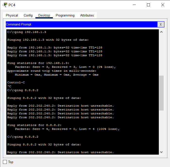
At this time, it is not successful to ping the PC2 (8.8.8.2) of Chongqing University by using the PC0 (192.168.1.2) inside Jiaotong University. The Destination host unreachable message will be displayed.

📬 Secret script
While ping ing, you can see very clearly by using Simulation in CPT software: the WAN port of Chongqing University router discards the packets from Jiaotong University
Next, let's start implementing PAT. That is, we will convert the internal / private IP address to the external / public IP address at the exit of Jiaotong University router, so that the source IP of the packet will not be discarded by Chongqing University router, so the network is connected.
Router PAT configuration of Jiaotong University:
Router>en   // Enter privileged mode from normal mode
Router#conf t / / enter global configuration mode
Router(config)#Access list 1 permit 192.168.1.0 0.0.255 / / create ACL 1 to allow all packets from the 192.168.1.0/24 network
Router(config)#ip nat inside source list 1 interface s0/0 overload / / the IP from the ACL will implement PAT on the WAN interface
Router(config)#int f0/0 / / configure Ethernet port
Router(config-if)#ip nat inside / / configure the Ethernet port as the internal port of PAT
Router(config)#int s0/0 / / configure WAN port
Router(config-if)#ip nat outside / / configure the WAN port as the external port of PAT
Now, it is OK to ping the PC2 (8.8.8.2) of Chongqing University by using the PC0 (192.168.1.2) inside Jiaotong University again.

📬 Secret script
After the ping is successful, use show ip nat translations in the privileged configuration mode of Jiaotong University router to view the translation process!
10, Virtual LAN VLAN
In the actual network (e.g Address of our school ), you can see that routers are generally located at the boundary of the network, and almost all of them are connected by switches.
As we analyzed earlier, the switch is connected to the same subnet! Obviously, broadcasting and even broadcasting storm in such a large-scale subnet will seriously affect the network performance and even paralysis.
In addition, we already know that in fact, the school is divided into N subnets, so these switches are not connected to a subnet! How to explain such contradictory things? We actually use VLAN enabled switches! The aforementioned switch is only an ordinary layer 2 switch (or we use it as a layer 2 switch).
VLAN (Virtual Local Area Network) is Virtual Local Area Network. By dividing VLANs, we can divide a physical network into multiple logical network segments, that is, multiple subnets.
After the VLAN is divided, the network broadcast storm can be eliminated, the network security can be enhanced, and it is convenient for unified management.
Build a topology in CPT as shown in the following figure:
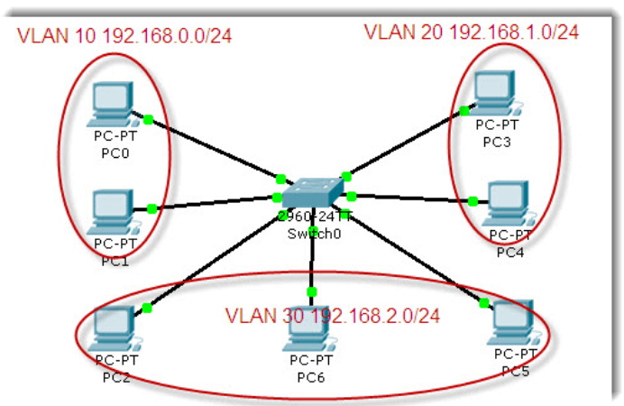
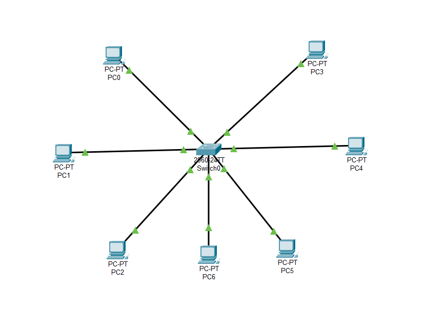
Cisco 2960 switch is a VLAN supporting switch with 24 100M and 2 1000M Ethernet ports. By default, all interfaces are in VLAN 1, so the connected computers are in the same VLAN and can communicate.
Next, the 24 100M interfaces of the switch are divided into three parts and divided into three different VLAN s. The id numbers are set to 10, 20 and 30 respectively, and aliases (computer, communication and electronic) are set to facilitate differentiation and management.
Switch VLAN configuration:
Switch>en
Switch#conf t
Switch(config)#vlan 10 / / create a VLAN with id 10 (by default, all interfaces of the switch belong to VLAN 1 and cannot be used)
Switch(config-vlan)#name computer / / set the alias of VLAN
Switch(config-vlan)#exit
Switch(config)#int vlan 10 / / the VLAN is a subnet. Set its IP as the subnet gateway
Switch(config-if)#ip address 192.168.0.1 255.255.255.0
Switch(config-if)#exit
Switch(config)#vlan 20 / / create a VLAN with id 20
Switch(config-vlan)#name communication / / set alias
Switch(config-vlan)#exit
Switch(config)#int vlan 20
Switch(config-if)#ip addr 192.168.1.1 255.255.255.0
Switch(config-if)#exit
Switch(config)#vlan 30 / / create a VLAN with id 20
Switch(config-vlan)#name electronic / / set alias
Switch(config-vlan)#exit
Switch(config)#int vlan 30
Switch(config-if)#ip add 192.168.2.1 255.255.255.0
Switch(config-if)#exit
Switch(config)#int range f0/1-8 / / group configuration interface (1-8)
Switch(config-if-range)#switchport mode access / / set to access mode
Switch(config-if-range)#switchport access vlan 10 / / classified into VLAN 10
Switch(config-if-range)#exit
Switch(config)#int range f0/9-16
Switch(config-if-range)#switchport mode access
Switch(config-if-range)#switchport access vlan 20
Switch(config-if-range)#exit
Switch(config)#int range f0/17-24
Switch(config-if-range)#switchport mode access
Switch(config-if-range)#switchport access vlan 30
Switch(config-if-range)#^Z
Switch#show vlan / / view the VLAN partition
So far, we have divided three VLANs on the switch (excluding the default VLAN 1).
The network configuration of PC under each VLAN and the connected switch interface are as follows:
| machine name | Connected interface | VLAN | IP | Subnet mask | gateway |
|---|---|---|---|---|---|
| PC0 | F0/1 | VLAN 10 | 192.168.0.2 | 255.255.255.0 | 192.168.0.1 |
| PC1 | F0/2 | VLAN 10 | 192.168.0.3 | 255.255.255.0 | 192.168.0.1 |
| PC2 | F0/17 | VLAN 30 | 192.168.2.2 | 255.255.255.0 | 192.168.2.1 |
| PC3 | F0/9 | VLAN 20 | 192.168.1.2 | 255.255.255.0 | 192.168.1.1 |
| PC4 | F0/10 | VLAN 20 | 192.168.1.3 | 255.255.255.0 | 192.168.1.1 |
| PC5 | F0/18 | VLAN 30 | 192.168.2.3 | 255.255.255.0 | 192.168.2.1 |
| PC6 | F0/19 | VLAN 30 | 192.168.2.4 | 255.255.255.0 | 192.168.2.1 |
At this time, you can use the ping command to test. You will find that only PC s in the same VLAN can communicate, and the broadcast is limited to the VLAN.
✎ thinking
Why can't PC s in different VLAN s communicate? What does the gateway do here? Where is our gateway? How do I initiate a broadcast test?
By dividing VLANs, ports in the same vlan can communicate directly without routers, while routers are required to route between different VLANs. As the entrance and exit of communication between VLANs, the gateway should be at the location of the router. The broadcast test is carried out in each vlan. vlan is used to isolate broadcast and avoid broadcast storm.
11, Virtual LAN management VTP
In the previous experiment, we planned and divided VLANs on the switch. However, in practical application, we will never allow arbitrary VLAN division on these switches that support VLAN, which will cause management confusion! VLAN division must be uniformly planned and managed, which requires VTP protocol.
VTP (VLAN Trunk Protocol) is the VLAN relay protocol. VTP maintains the uniformity of VLAN configuration through ISL frame or Cisco private DTP frame (refer to relevant materials). It is also known as virtual LAN trunk protocol. It is Cisco private protocol. VTP uniformly manages, adds, deletes and adjusts VLANs, and automatically broadcasts information to other switches in the network.
In addition, VTP reduces the configurations that may cause security problems. As long as the corresponding settings are made in the VTP Server, the VTP Client will automatically learn the VLAN information on the VTP Server.
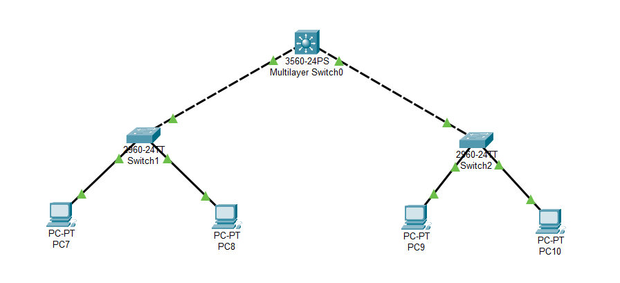
To demonstrate VTP, rebuild the following topology:
🗣 be careful:
As the trunk line, the two 2960 switches and the core 3560 switch should be connected by Gbit port. Although this is not necessary, in reality, this connection performance is the best.
3560 switch is the core switch in the network. We regard it as VTP Server, and VTP domain and VLAN will be created and managed on it.
The two 2960 switches are the convergence layer / access layer switches in the LAN. They will act as VTP clients and can decide the VTP domain and VLAN to join.
At present, the network belongs to VLAN 1, that is, these PC s can communicate with each other. As mentioned earlier, in reality, we must divide VLANs for performance, management and security.
Now our requirement is to create two VLANs, and then let PC0 and PC1 belong to VLAN 2, and PC1 and PC3 belong to VLAN 3.
We will do the following work on the core switch 3560:
- Set to server mode and VTP domain to cqjtu
- New VLAN 2, network number 192.168.1.0/24, gateway 192.168.1.1
- New VLAN 3, network number 192.168.2.0/24, gateway 192.168.2.1
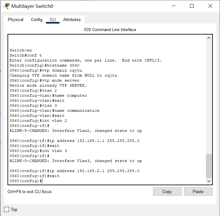
3560 VTP Server configuration:
Switch>en
Switch#conf t
Switch(config)#hostname 3560 / / change the switch name (optional)
3560(config)#vtp domain cqjtu / / set the VTP domain name to cqjtu
3560(config)#vtp mode server / / set it to VTP server mode
3560(config)#VLAN 2 / / create a new VLAN 2
3560(config-vlan)#name computer / / set the alias of VLAN 2 (optional)
3560(config-vlan)#exit
3560(config)#VLAN 3 / / rebuild VLAN 3
3560(config-vlan)#name communication / / set the alias of VLAN 2 (optional)
3560(config-vlan)#exit
3560(config)#int vlan 2 / / configure interface VLAN 2, which will be the gateway of the subnet (on the left)
3560(config-if)#ip address 192.168.1.1 255.255.255.0
3560(config-if)#exit
3560(config)#int vlan 3 / / configure interface VLAN 3, which will be the gateway of the subnet (on the right)
3560(config-if)#ip address 192.168.2.1 255.255.255.0
We will do the following work on the left switch 2960A:
- Join a VTP domain named cqjtu
- Configure the Gigabit interface g0/1 connected to the core switch 3560 as trunk mode
- Divide interface f0/1 into VLAN 2
- Divide interface f0/2 into VLAN 3
2960A (left) VTP Client configuration:
Switch>en
Switch#conf t
Switch(config)#hostname 2960A / / change the switch name (optional)
2960A(config)#vtp domain cqjtu / / join a VTP domain named cqjtu
2960A(config)#vtp mode client / / set the mode to VTP client
2960A(config)#int g0/1 / / configure the g0/1 Gigabit interface connected to the core switch 3560
2960A(config-if)#switchport mode trunk / / set the interface to trunk mode
2960A(config-if)#switchport trunk allowed vlan all / / allow trunking for all VLANs
2960A(config-if)#exit
2960A(config)#int f0/1 / / configure interface 1
2960A(config-if)#switchport mode access / / set the interface to normal access mode
2960A(config-if)#switchport access vlan 2 / / divide the interface into VLAN 2
2960A(config-if)#exit
2960A(config)#int f0/2 / / configure interface 2
2960A(config-if)#switchport mode access / / set the interface to normal access mode
2960A(config-if)#switchport access vlan 3 / / divide the interface into VLAN 3

We will do the same on the right switch 2960B:
- Join a VTP domain named cqjtu
- Configure the Gigabit interface g0/1 connected to the core switch 3560 as trunk mode
- Divide interface f0/1 into VLAN 2
- Divide interface f0/2 into VLAN 3
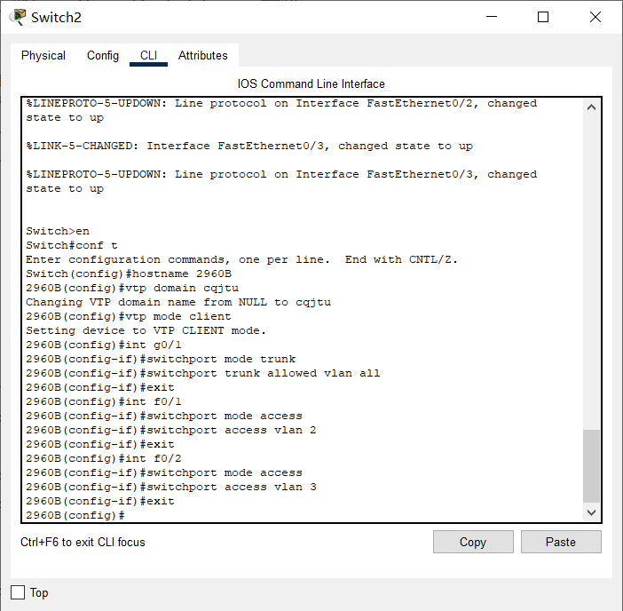
2960B (right) VTP Client configuration:
Switch>en
Switch#conf t
Switch(config)#hostname 2960B / / change the switch name (optional)
2960B(config)#vtp domain cqjtu / / join a VTP domain named cqjtu
2960B(config)#vtp mode client / / set the mode to VTP client
2960B(config)#int g0/1 / / configure the g0/1 Gigabit interface connected to the core switch 3560
2960B(config-if)#switchport mode trunk / / set the interface to trunk mode
2960B(config-if)#switchport trunk allowed vlan all / / allow trunking for all VLANs
2960B(config-if)#exit
2960B(config)#int f0/1 / / configure interface 1
2960B(config-if)#switchport mode access / / set the interface to normal access mode
2960B(config-if)#switchport access vlan 2 / / divide the interface into VLAN 2
2960B(config-if)#exit
2960B(config)#int f0/2 / / configure interface 2
2960B(config-if)#switchport mode access / / set the interface to normal access mode
2960B(config-if)#Partition VLAN access to VLAN 3 / / access interface
So far, each switch is configured.
📬 Secret script
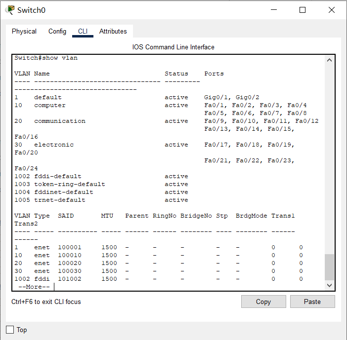
At this time, in the privileged mode of the three switches, you can use the show vtp status command to view the VTP status and the show vlan command to view the VLAN
state
The switches, interfaces and network configurations connected to each PC are as follows:
| machine name | Connected switches and interfaces | VLAN | IP | Subnet mask | gateway |
|---|---|---|---|---|---|
| PC0 | 2960A-F0/1 | VLAN 2 | 192.168.1.2 | 255.255.255.0 | 192.168.1.1 |
| PC1 | 2960A-F0/2 | VLAN 3 | 192.168.2.2 | 255.255.255.0 | 192.168.2.1 |
| PC2 | 2960B-F0/1 | VLAN 2 | 192.168.1.3 | 255.255.255.0 | 192.168.1.1 |
| PC3 | 2960B-F0/2 | VLAN 3 | 192.168.2.3 | 255.255.255.0 | 192.168.2.1 |
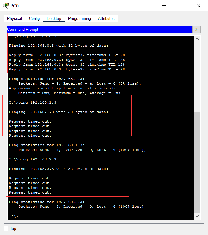
The VTP configuration is now complete. The same VLAN can be ping ed, but different VLANs can't (even under the same switch, such as PC0 to PC1), and it can facilitate unified planning and management.
✎ give it a try
What is the result of pinging PC1 (192.168.2.2) with PC0 (192.168.1.2)? Ping PC2 with PC0
What was the result? Think about why?
PC0 ping PC1 cannot Ping, PC0 ping PC2 can ping, because PC0 and PC2 belong to the same vlan, while PC0 and PC1 do not belong to the same valn.
12, Communication between VLAN s
VTP only provides convenience for us to divide and manage VLANs. According to the above tests, we still can't communicate between VLANs.
Because by default, communication between VLANs is not allowed. At this time, we need the so-called single arm router to forward it between VLANs!
The core switch 3560 we use is a layer 3 switch, which can work in the network layer, also known as the routing switch, that is, it has the routing function and can carry out this forwarding operation.
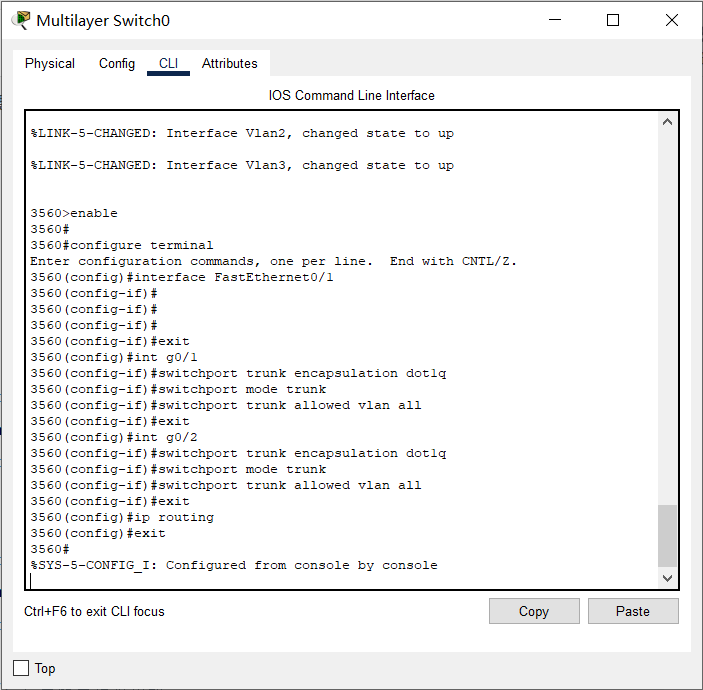
3560 switch configuration:
3560>en
3560#conf t
3560(config)#int g0/1 / / configure the interface connecting the 2960A switch on the left
3560(config-if)#switchport trunk encapsulation dot1q / / encapsulating VLAN protocol
3560(config-if)#switchport mode trunk / / set to relay mode
3560(config-if)#switchport trunk allowed vlan all / / forward between all VLANs
3560(config-if)#exit
3560(config)#int g0/2 / / configure the interface connecting the 2960B switch on the right
3560(config-if)#switchport trunk encapsulation dot1q / / encapsulating VLAN protocol
3560(config-if)#switchport mode trunk / / set to relay mode
3560(config-if)#switchport trunk allowed vlan all / / forward between all VLANs
3560(config-if)#exit
3560(config)#ip routing / / enable routing forwarding
So far, PC s in each VLAN can communicate normally.
🗣 Defects of one arm routing
When you use the CPT simulation method for the above test (PC0 ping PC1), you will clearly see that all ICMP packets are made of 3560
When the switch is forwarding, it is very easy to form a bottleneck.
In reality, we generally do not use this method, but really use its three-layer forwarding function, that is, "one route and multiple exchanges". Please refer to relevant materials.
13, Simple configuration of DHCP, DNS and Web server
Dynamic host configuration DHCP, domain name resolution DNS and Web services play a great role in daily applications. Let's build the following simple topology for practice.
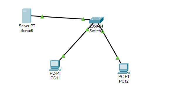
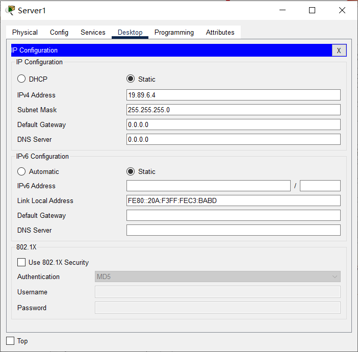
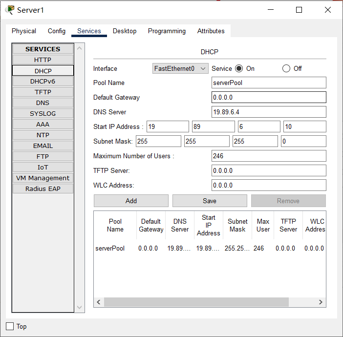
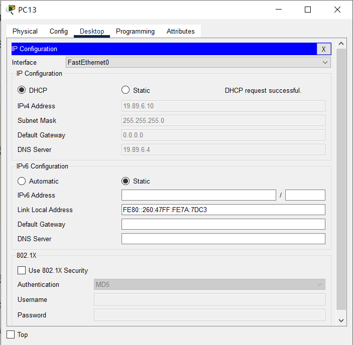
In this topology, both servers and clients are connected to the same switch. For simplicity, the Server-PT serves as DHCP, DNS and Web servers at the same time. Each client does not need to be configured and will automatically obtain the network configuration.
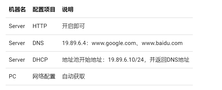
Click the Server icon in the CPT topology diagram, set its static IP address to 19.89.6.4/24, and then select Service for the following related configurations:
✎ give it a try
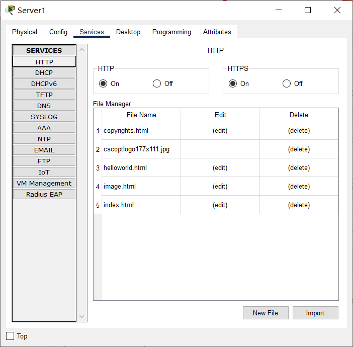
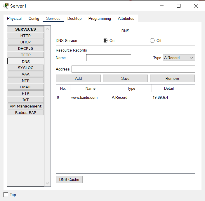
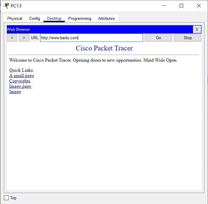
First check each PC to see if the network configuration is obtained, because we set the IP of Google and Baidu to 19.89.6.4 in the DNS server, that is
Server Pt, so if you open the browser of PC0, enter www.google.com Com or
www.baidu.com, we should all see the default server Pt, the home page of the Web server (you can also edit it)
14, WLAN Preliminary Configuration
WLAN, namely WiFi, is also widely used in various scenarios.
Let's practice the related configuration by building a home WLAN with the following topology:
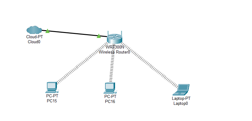
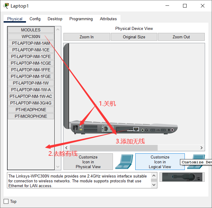
📬 Secret script
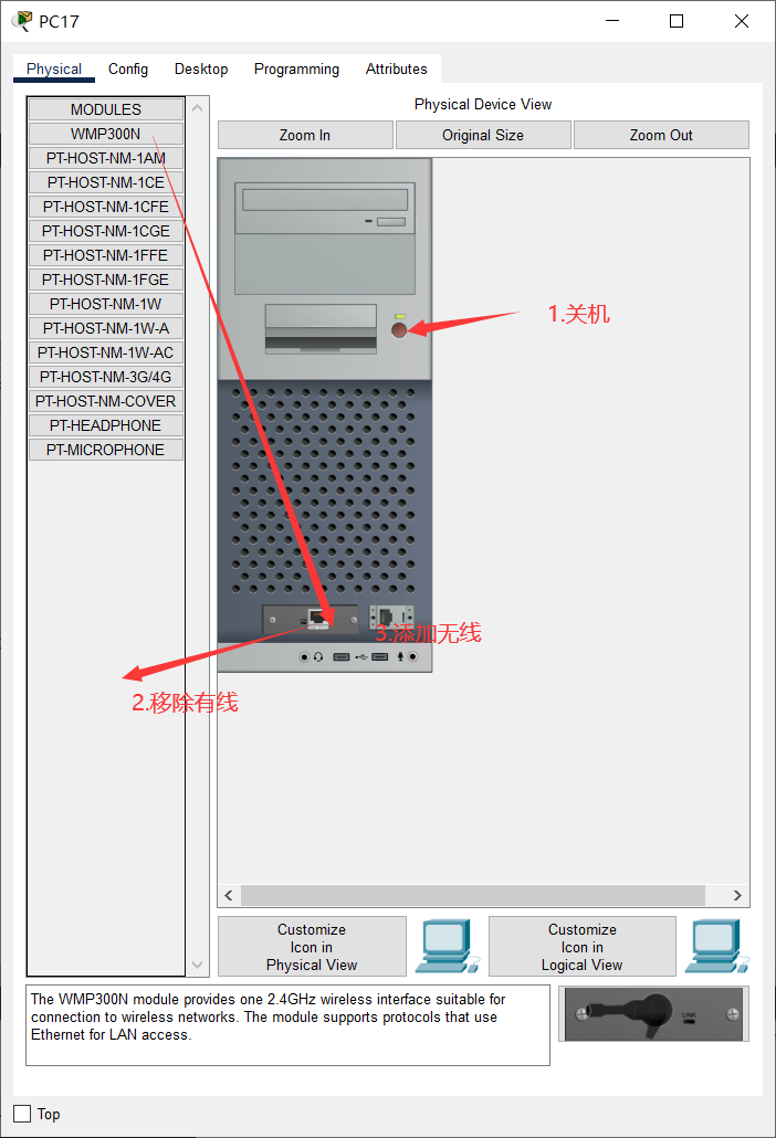
Notebook and desktop computers only have wired network cards by default. Please shut down first, delete the wired network card in the shutdown state, add a wireless network card, and then turn on.
Generally, we need to configure the basic network configuration of the wireless router (IP, mask, gateway, DNS, etc., which are mostly obtained automatically in reality), then configure the wireless access part of the wireless router, such as connection password and encryption type, and turn on the DHCP function. Please refer to relevant materials for configuration.