1, What is Bluetooth?
Bluetooth is a short-range wireless communication technology, which can realize the data exchange between fixed devices and mobile devices. Generally, BR/EDR Bluetooth before Bluetooth 3.0 is called traditional Bluetooth, while LE Bluetooth under Bluetooth 4.0 specification is called low-power Bluetooth.
Many people's understanding of Bluetooth is still limited to the field of mobile phones. In fact, the application of Bluetooth is far more than that. In the past few years, the growth of Bluetooth has reached 80%. Of course, the emergence of low-power Bluetooth also plays a key role. I believe Bluetooth will create an interactive IOT world in the future.
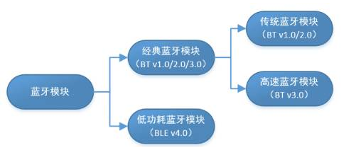
Bluetooth 4.0 standard includes traditional Bluetooth module and low-power Bluetooth module. It is a dual-mode standard. Low power Bluetooth is also developed on the basis of traditional Bluetooth, which is different from traditional modules. The biggest feature is the reduction of cost and power consumption, and the application requires high real-time performance.
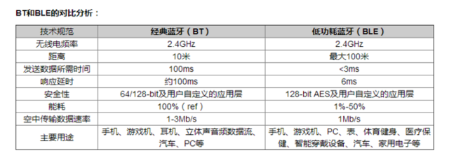
BLE (Bluetooth low energy) Bluetooth low energy technology is a wireless technology with short distance, low cost and interoperability. It uses many intelligent means to minimize power consumption.
The working mode of BLE technology is very suitable for transmitting data from micro wireless sensors (exchanging data every half a second) or other peripherals such as remote controllers using fully asynchronous communication. These devices send very little data (usually a few bytes) and very few times (for example, several times per second to once per minute, or even less).
2, Structure and configuration of BLE protocol stack
1. There are two parts: Host and Controller
2. Profiles and applications are always based on GAP and GATT
3. In the single chip solution, the Controller, Host, profiles, and application layer are all on the same chip
4. In the network Controller mode, the Host and Controller run together, but the application and profiles can be operated on another device, such as PC or other microcontroller, through UART and USB
5. In the dual chip mode, the Controller runs on one Controller, while the application layer, profiles and Host run on another Controller
3, Functional mechanism of BLE protocol stack
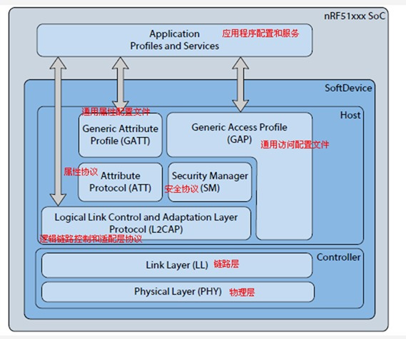
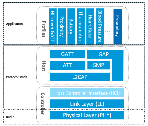
As shown in the figure above, to implement a BLE application, first you need a chip that supports BLE RF, then you need to provide a BLE protocol stack supporting this chip, and finally develop your own application on the protocol stack. It can be seen that BLE protocol stack is the bridge between chip and application, and the key to realize the whole BLE application. What functions does BLE protocol stack contain? In short, BLE protocol stack is mainly used to package your application data layer by layer to generate an air data packet that meets BLE protocol, that is, wrap the application data in a series of header and tail. Specifically, BLE protocol stack is mainly composed of the following parts:
-
PHY layer (Physical layer).
PHY layer is used to specify the wireless frequency band, modulation and demodulation mode and method used by BLE. The performance of PHY layer directly determines the power consumption, sensitivity, selectivity and other RF indicators of the whole BLE chip. -
LL layer (Link Layer).
Ll layer is the core of the whole BLE protocol stack, and it is also the difficulty and focus of BLE protocol stack. For example, the BLE protocol stack of Nordic can support 20 links at the same time, which is the credit of the LL layer. The LL layer has a lot to do, such as which RF channel to choose for communication, how to identify the air data packet, at which time point to send the data packet, how to ensure the integrity of the data, how to receive the ACK, how to retransmit, and how to manage and control the link. The LL layer is only responsible for sending or receiving the data, and how to analyze the data is handed over to the GAP or ATT above. -
HCI(Host controller interface).
HCI is optional. HCI is mainly used when two chips implement BLE protocol stack to standardize the communication protocol and communication commands between them. -
GAP layer (Generic access profile).
GAP is one of the two ways to analyze the LL layer payload (effective packet), and it is the simplest one. GAP simply regulates and defines LL payload, so the functions that GAP can realize are extremely limited. At present, GAP is mainly used for broadcasting, scanning and initiating connections. -
L2CAP layer (Logic link control and adaptation protocol).
L2CAP simply encapsulates LL. Ll only cares about the transmitted data itself. L2CAP should distinguish between encrypted channel and ordinary channel, and manage the connection interval at the same time. -
SMP(Secure manager protocol).
SMP is used to manage the encryption and security of BLE connection. How to ensure the security of connection without affecting the user experience is what SMP should consider. -
ATT(Attribute protocol).
In short, the att layer is used to define the data of user commands and command operations, such as reading a data or writing a data. In BLE protocol stack, ATT is the most contacted by developers. BLE introduces the concept of attribute to describe data one by one. Attribute not only defines data, but also defines att commands that can be used by the data. Therefore, this layer is called att layer. -
GATT(Generic attribute profile ).
GATT is used to standardize the data content in attributes, and uses the concept of group to classify and manage attributes. Without GATT, BLE protocol stack can run, but interconnection will have problems. It is precisely because of GATT and various application profile s that BLE gets rid of the compatibility dilemma of ZigBee and other wireless protocols and becomes the 2.4G wireless communication product with the largest shipment.
4, Main application fields of BLE Bluetooth module
- Mobile expansion device
- Automotive electronic equipment
- Health and medical supplies: heartbeat band, sphygmomanometer, etc
- Positioning application: indoor positioning, underground positioning, etc
- Short range data acquisition: wireless meter reading, wireless telemetry, etc
- Data transmission: smart home indoor control, Bluetooth dimming, printer, etc
5, BLE protocol stack details
Protocol overview
The so-called protocol means that the specified bytes are arranged in a certain order so that others can communicate with other devices through the protocol when using their own devices. One feature of the protocol is that it has a fixed frame format, which is sent through, and the receiver can get the new information content by interpreting the frame format;
BLE connection process
General communication protocol: one type of communication is to directly generate data. When the equipment receives and sends the data, it will directly analyze the data. When the received data is legal, it is valid data. This type of communication protocol is mainly used in wired communication protocols, such as Modbus and Can. This type of communication mode is commonly used.
For another type of communication protocol, a new connection needs to be established. When the connection between both parties is established successfully, they can communicate, such as TCP and BLE; When the BLE protocol needs to communicate, it needs to send a broadcast signal to the outside to tell the receiver that it is about to communicate with it. After receiving the broadcast content, the receiver confirms that it is communicating with itself, so it sends a response message to the broadcaster. In this way, when both the broadcaster and the receiver have the identity information of each other, it means that the connection between the two sides is successful.
Therefore, in the connection process, there must be A corresponding broadcast frame format. In the process of BLE communication, assuming that device A needs to connect with other devices, assuming that it is B, then A needs to continuously send broadcast signals (this process generally has A time interval, and the chip is in A low-power state during the time when broadcast data is not sent). Each broadcast packet sent is called A broadcast event.
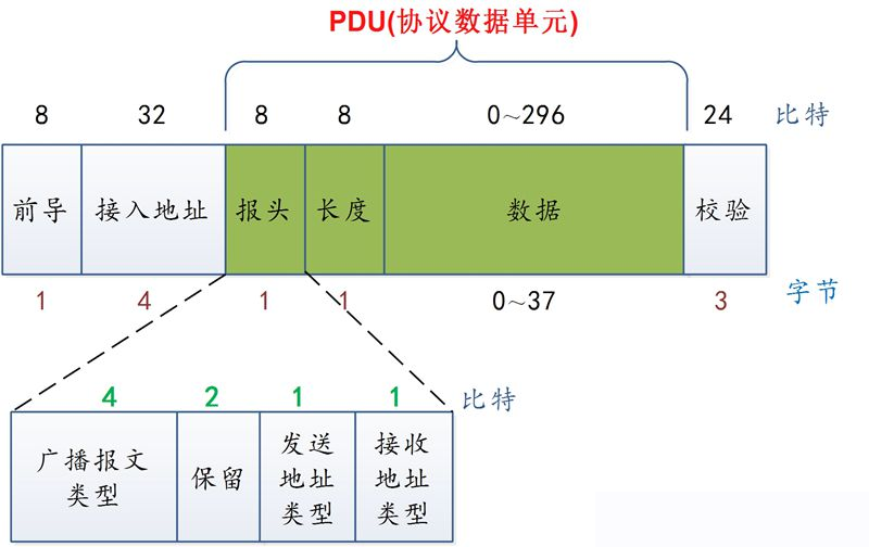
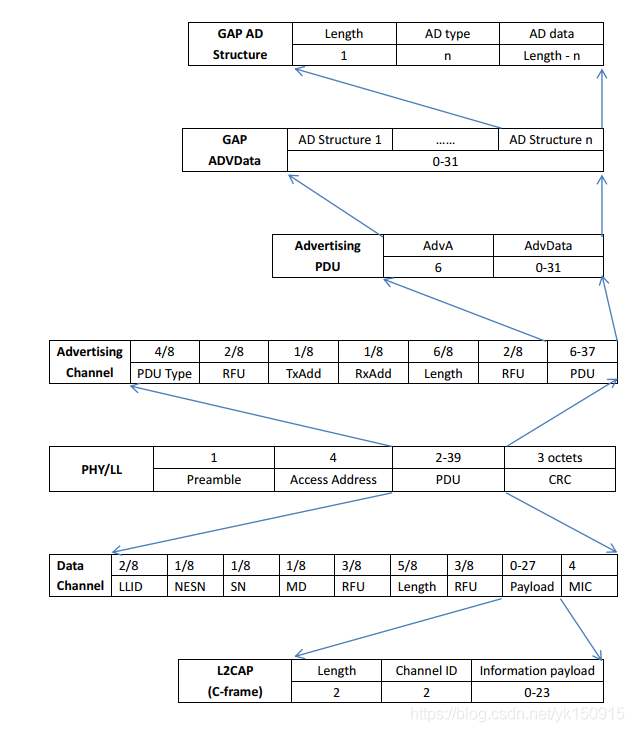
Leading:
Is an 8-bit alternating sequence
The first bit of the access address is 0:01010101
The first bit of the access address is 1:10101010
Access address: broadcast frame is fixed address: 0x8E89BED6 (low byte first)
Header of broadcast message:
It includes 4-bit broadcast message type, 2-bit reserved bit, 1-bit sending address type and 1-bit receiving address type.
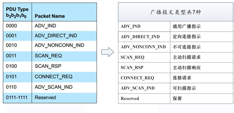
Broadcast message type:
Sending address type:
0: public address
1: Random address
Length: the length field of broadcast message contains 8 bits, and the range of valid values is 6 ~ 37
Data: broadcaster address (6 bytes) + broadcast data (31 bytes)
Check: 3 bytes, CRC check.
Broadcast data: divided into valid data and invalid data
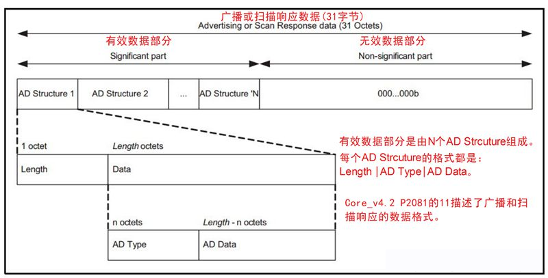
Valid data part:
It contains N ad structures. Each AD Structure consists of Length, AD Type and AD Data. Of which:
Length: the length of AD Type and AD Data.
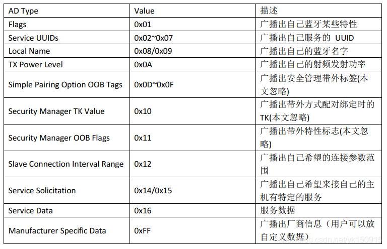
AD Type: indicates the meaning of AD Data.
See details https://www.bluetooth.com/specifications/assigned-numbers/generic-access-profile/
6, BLE connection establishment process
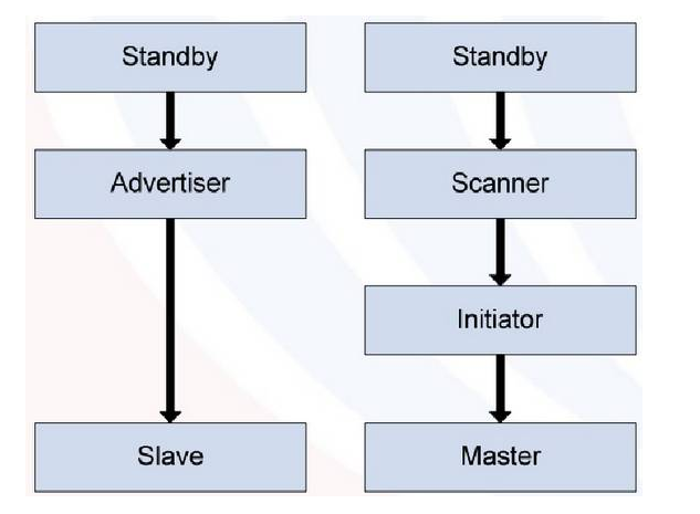
1. BLE broadcast and scanning
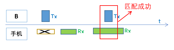
equipment B Constantly sending broadcast signals to mobile phones( Observer),If the mobile phone does not open the scanning window, the mobile phone cannot receive the device B As shown in the figure below, not only should the mobile phone open the RF receiving window, but also the mobile phone can receive the device only if the RF receiving window of the mobile phone matches the transmitting window of the broadcast successfully, and the broadcast RF channel and the mobile phone scanning RF channel are the same channel B Broadcast signal. That is, if the device B If a broadcast packet is sent on channel 37 and the mobile phone is scanning channel 38, even if their RF windows match, they cannot communicate. Since this matching success is a probability event, the mobile phone scans the device B It is also a probability event, that is, the mobile phone sometimes scans the device quickly B,For example, only one broadcast event is needed, and sometimes the mobile phone will be very slow to scan the device B,For example, 10 broadcast events or more are required.
2. connection establishment
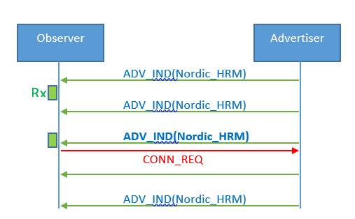
According to Bluetooth spec regulations, advertiser 150 after sending a broadcast packet us(T_IFS),advertiser The RF must be turned on for a period of time Rx Window to receive from observer Data package. Observer You can give it during this time advertiser Send connection request. As shown in the following figure, when the broadcast device is scanned to the third event B,And issued a connection request CONN_REQ(CONN_REQ Also known as CONNECT_IND).
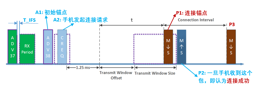
Note: in the figure, M represents mobile phone, s represents device B, and M - > s represents that the mobile phone sends data packets to device B, that is, the mobile phone opens Tx window and device B opens Rx window; S - > m is just the opposite, indicating that device B sends data packets to the mobile phone, that is, device B opens the Tx window and the mobile phone opens the Rx window.
As shown in the figure, the mobile phone receives the A1 broadcast packet adv_ After ind, take this as the initial anchor point (this anchor point is not the connected anchor point), t_ After the IFS time, send a connection request command to the advertiser, that is, A2 packet, and tell the advertiser that I will come to connect you. Please be ready. Advertiser connect_req command information is ready for reception, connect_req contains the following key information:
- Transmit window offset is defined as shown above
- The definition of Transmit window size is shown in the figure above
- connect_ The complete definition of req packet is as follows:
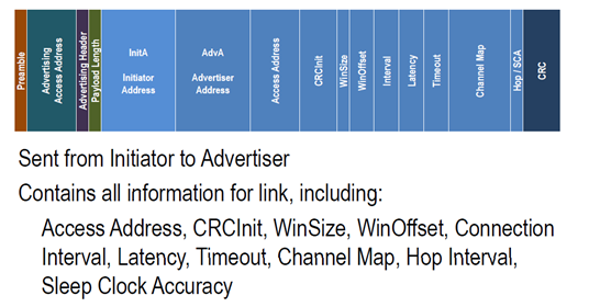
connect_req is actually telling the advertiser that the phone will send the first synchronization packet (P1) to you during the Transmit Window. Please open your RF receiving window during this time. After device B receives P1, t_ After the IFS time, the mobile phone will reply to packet P2 (ACK packet).
Once the mobile phone receives the packet P2, the connection can be considered to be established successfully. Of course, the actual situation will be more complicated. The mobile phone may not receive P2. At this time, the mobile phone will continue to send synchronization packets until the supervision timeout. During this period, as long as device B returns the ACK packet once, the connection is successful. Therefore, once the P1 packet is sent, the host (mobile phone) considers the connection successful, regardless of whether the ACK packet of the device is received or not.
This is also why in Android or iOS systems, applications often receive callback events of successful connection (the callback event is based on whether the P1 package is sent or not. As long as the P1 package is sent, the mobile phone will consider the connection successful, regardless of whether the ACK package of the device is received or not), but in fact, the mobile phone and the device have not successfully established a connection.
Subsequent mobile phones will periodically send packets to device B with P1 as the anchor point (origin) and Connection Interval as the cycle. In addition to serving as data transmission function, Packet also has the following two very important functions:
Synchronize the clock of the mobile phone and the device, that is, every time the device receives a packet from the mobile phone, it will reset its timing origin to synchronize with the mobile phone.
Tell the device that you can send data to me now. After successful connection, BLE communication will become Master-Slave mode. Therefore, the connection initiator (mobile phone) is called Master or Central, and the connected person (formerly Advertiser) is called Slave or Peripheral.
The reason why BLE communication is in the Master-Slave mode is that Slave cannot "randomly" send messages to the Master. It can only send its own data back to the Master at the specified time after the Master sends it a packet.
3. Connection failure
There are several typical connection failures:
-
As shown in the figure in step 2, if the slave does not receive P1 from the master during the transmit window, the connection will fail. At this time, you should check the problem on the master side to see why the master did not send P1 at the agreed time.
-
If the master sends P1 during the transmit window, that is to say, the master follows connect_ If P1 is sent out according to the timing agreed in req, but the slave does not return P2 or does not return P2 within the timeout, the connection will also fail. At this time, you should check the problem on the slave side and see why the slave did not return P2
-
If the master sends P1 and the slave sends P2 back, the master or slave still reports a connection failure. This may be a software problem. You need to carefully check the master or slave software.
-
There is also a common connection failure: too much RF interference in the air. At this time, we should find a clean environment, such as shielding room, and test whether the connection is normal after eliminating the interference.
7, Frame format
1. Data link layer message structure
The message is based on the message of data link layer, and other messages are expanded from here. The data format of BLE data link layer is as follows:
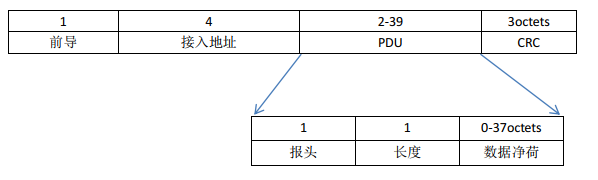
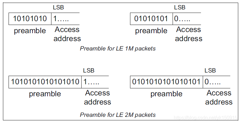
In the latest core spec 5.2, there are 1M PHY and 2M PHY, and the corresponding preamble becomes 1-2 bytes. The preamble is used for frequency synchronization, timing evaluation and automatic gain control training. The first bit of the preamble should be the same as the LSB of the access address.
 Field resolution:
Message type (lower 4 bit s):
ADV_IND (0000) - general broadcast
ADV_DIRECT_IND (0001) - directional connection broadcast
ADV_NONCONN_IND (0010) - unconnected broadcast
ADV_SCAN_IND (0110) - scannable broadcast
SCAN_REQ (0011) - active scan request
SCAN_RSP (0100) - active scan response
CONNECT_REQ (0101) - connection request
Sending address (TXADD) and receiving address (RXADD): when this bit is "1", it means Random Add; when this bit is "0", it means Public Add. This address refers to the first few address bytes in the data payload.
Payload length: this length refers to the effective payload data length of the data in the PDU excluding the header and length.
2. Difference between broadcast channel and data channel PDU:
PDU format of broadcast channel:
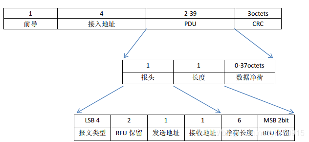
Field resolution:
Message type (lower 4 bit s):
ADV_IND (0000) - general broadcast
ADV_DIRECT_IND (0001) - directional connection broadcast
ADV_NONCONN_IND (0010) - unconnected broadcast
ADV_SCAN_IND (0110) - scannable broadcast
SCAN_REQ (0011) - active scan request
SCAN_RSP (0100) - active scan response
CONNECT_REQ (0101) - connection request
When this bit is "rxam" and "add", it indicates the random address (TX and "add"). When this bit is "add", it indicates the random address (TX). This address refers to the first few address bytes in the data payload.
Payload length: this length refers to the effective payload data length of the data in the PDU excluding the header and length.
PDU format of data channel:
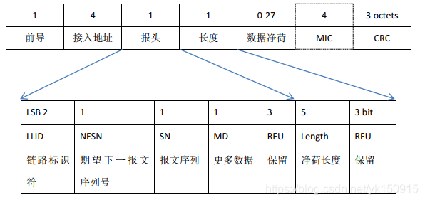
Field definition:
LLID:
Indicates whether the package data is LL Date PDU or LL Control PDU
00b: Reserved
01b: LL Date PDU: Continuation fragment of L2CAP message, or an Empty PDU.
10b: LL Date PDU: Start of an L2CAP message or a complete L2CAP message with no fragmentation.
11b: LL Control PDU
MIC( Message Integrity Check):
Information integrity detection. When it comes to encryption, the above figure is represented by dotted lines, which is not necessary.
MD:
This flag bit is used to inform the other device that it has other data to send. 0 means no more data is sent, and 1 means more data is ready to be sent. In this way, as long as there is data to be sent, the connection event will expand automatically. Once no more data is sent, the connection event is closed immediately.
Note: how to distinguish between new package and reissued package?
SN:
There is only one bit, so the value is switched between 0 and 1. If the serial number is the same as the previous one, it is a retransmission message. If the serial number is different from the previous one, it is a new message.
NESN:
Expected serial number, which is the serial number of the next packet that the receiver wants to receive, that is, the confirmation flag of the data packet. When the device receives the message with sequence (SN) of 0, it shall set NESN to 1 in the data packet sent to the other party, so that the other party will send a new data packet after receiving the packet, otherwise it will resend the last packet with sequence number of 0. This flag can be used to determine whether the packet is received correctly or needs to be retransmitted.
3. BLE message format
4. AD Structure analysis
(1) AD type
(2) AD data overview
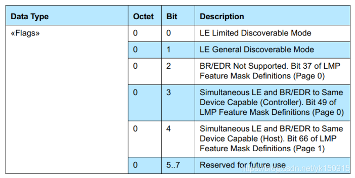
Flags:
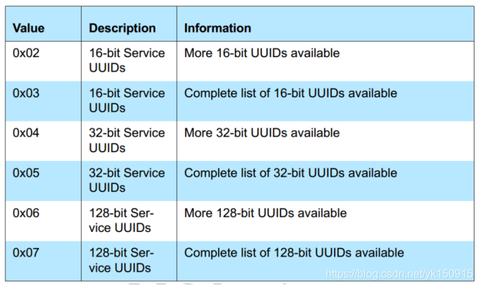
SERVICE:
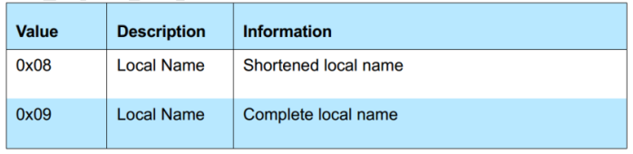
Local Name:
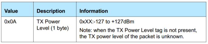
TX Power Level:
8, Code example
This example takes BLE code under OSAL as an example to explain.
What is OSAL?
OSAL is: Operating System Abstraction Layer, that is, the Operating System Abstraction Layer, which supports multitasking. It is not an operating system in the traditional sense, but realizes some functions similar to the operating system.
The concept of OSAL is introduced by TI company in ZIGBEE protocol stack. It means "analog operating system". This OS is not a real OS, but some methods of simulating OS, which provides a way for programmers to write MCU programs. When an event occurs, OSAL is responsible for assigning the event to a task that can handle the event, and then the task judges the type of event and calls the corresponding event handler for processing.
Experimental platform
1. Bluetooth protocol stack: 1.3.2
2. Software platform: IAR For 8051 8.10.3
3. Hardware platform: Smart RF development board (slave), Android_Lightblue (host)
Code parsing
- int main(void)
int main(void)
{
  /* Initialize hardware */
  HAL_BOARD_INIT();//Initialize clock and enable cache prefetch mode

  // Initialize board I/O
  InitBoard( OB_COLD );//Cold start, turn off the led light and interrupt to avoid the interference of subsequent initialization

  /* Initialze the HAL driver */
  HalDriverInit();//Initialization of various drivers, such as keys, lcd, adc, usb, uart, etc

  /* Initialize NV system */
  osal_snv_init();//snv internal flash, 4kB space used to save pairing data or your user-defined data

  /* Initialize LL */
  /* Initialize the operating system */
  osal_init_system();//oasl operating system initialization, including memory allocation, message queue, timer, power management and tasks

  /* Enable interrupts */
  HAL_ENABLE_INTERRUPTS();// Turn on global interrupt

  // Final board initialization
  InitBoard( OB_READY );  //Set signs to indicate that the system is initialized
}
- osal_init_system()
uint8 osal_init_system( void )
{
  // Initialize the Memory Allocation System
  osal_mem_init();//Initialize memory allocation system

  // Initialize the message queue
  osal_qHead = NULL;//Initialize message queue

  // Initialize the timers
  osalTimerInit();//Initialization timer

  // Initialize the Power Management System
  osal_pwrmgr_init();//Initialize the power management system

  // Initialize the system tasks.
  osalInitTasks();//Initialize the system task, which is very critical

  // Setup efficient search for the first free block of heap.
  osal_mem_kick();

  return ( SUCCESS );
}
- osalInitTasks()
void osalInitTasks( void )
{
  /* L2CAP Task */
  L2CAP_Init( taskID++ );

  /* GAP Task */
  GAP_Init( taskID++ );

  /* GATT Task */
  GATT_Init( taskID++ );

  /* SM Task */
  SM_Init( taskID++ );

  /* Profiles */
  GAPRole_Init( taskID++ );    //Link role initialization
  GAPBondMgr_Init( taskID++ );  //Link binding initialization
  GATTServApp_Init( taskID++ );
  /* Application */
  SimpleBLEPeripheral_Init( taskID );
}
- GAPRole_Init( taskID++ )
void GAPRole_Init( uint8 task_id )
{
  gapRole_TaskID = task_id;  //Define task address

  gapRole_state = GAPROLE_INIT;  //The link status is set to gaprol_ INIT
  gapRole_ConnectionHandle = INVALID_CONNHANDLE;  //Set the link connection handle to 0xFFFF
  GAP_RegisterForHCIMsgs( gapRole_TaskID );//Register the task ID of the control interface

  // Initialize the Profile Advertising and Connection Parameters
  gapRole_profileRole = GAP_PROFILE_PERIPHERAL;  //The link configuration role is slave
  VOID osal_memset( gapRole_IRK, 0, KEYLEN );    //Key buffer reset
  VOID osal_memset( gapRole_SRK, 0, KEYLEN );
  gapRole_signCounter = 0;                       //Key count flag bit reset
  gapRole_AdvEventType = GAP_ADTYPE_ADV_IND; //The broadcast type is connectable non directional broadcast
  gapRole_AdvDirectType = ADDRTYPE_PUBLIC; //Broadcast mode is through broadcast (can be found and connected by scanning)
  gapRole_AdvChanMap = GAP_ADVCHAN_ALL ;  //Broadcast all channels 37, 38, 39
  gapRole_AdvFilterPolicy = GAP_FILTER_POLICY_ALL;  //Allow scanning and connection
  // Restore Items from NV
  VOID osal_snv_read( BLE_NVID_IRK, KEYLEN, gapRole_IRK ); //Read out the stored key and key count flag bit
  VOID osal_snv_read( BLE_NVID_CSRK, KEYLEN, gapRole_SRK );

  VOID osal_snv_read( BLE_NVID_SIGNCOUNTER, sizeof( uint32 ), &gapRole_signCounter );
}
- SimpleBLEPeripheral_Init
//After initialization

void SimpleBLEPeripheral_Init( uint8 task_id )
{
	osal_set_event( simpleBLEPeripheral_TaskID, SBP_START_DEVICE_EVT );              //Start device start event
}
- SimpleBLEPeripheral_ProcessEvent
uint16 SimpleBLEPeripheral_ProcessEvent( uint8 task_id, uint16 events )
{
  if ( events & SBP_START_DEVICE_EVT )// Execute this after initialization
      {
            // Start the Device
            VOID GAPRole_StartDevice( &simpleBLEPeripheral_PeripheralCBs ); //Configure link event notification callback function

            // Start Bond Manager
            VOID GAPBondMgr_Register( &simpleBLEPeripheral_BondMgrCBs ); //Configure pairing message callback function

            // Set timer for first periodic event
            osal_start_timerEx( simpleBLEPeripheral_TaskID, POWER_DETECT_EVT, DetectPowerPeriod );

            return ( events ^ SBP_START_DEVICE_EVT );
      }
}
- GAPRole_StartDevice
Status_t GAPRole_StartDevice( gapRolesCBs_t *pAppCallbacks )
{
  if ( gapRole_state == GAPROLE_INIT ) //If the link state is initialized
  {
    // Clear all of the Application callbacks
    if ( pAppCallbacks )
    {
      pGapRoles_AppCGs = pAppCallbacks;//Set callback function
    }

    // Start the GAP
    gapRole_SetupGAP();//Start establishing link
    return ( SUCCESS );
  }
  else     //Otherwise, it returns the status that is already in the request mode
  {
    return ( bleAlreadyInRequestedMode );
  }
}
- gapRole_SetupGAP
static void gapRole_SetupGAP( void )
{
  VOID GAP_DeviceInit( gapRole_TaskID,
          gapRole_profileRole, 0,
          gapRole_IRK, gapRole_SRK,
          &gapRole_signCounter );
}
- GAP_DeviceInit
bStatus_t GAP_DeviceInit(  uint8 taskID,
                           uint8 profileRole,
                           uint8 maxScanResponses,
                           uint8 *pIRK,
                           uint8 *pSRK,
                           uint32 *pSignCounter )
{
    // Setup the device configuration parameters
stat = GAP_ParamsInit( taskID, profileRole );  //Set device configuration parameters

    #if ( HOST_CONFIG & ( CENTRAL_CFG | PERIPHERAL_CFG ) )
    {
      GAP_SecParamsInit( pIRK, pSRK, pSignCounter );
    }
#endif
#if ( HOST_CONFIG & ( PERIPHERAL_CFG | BROADCASTER_CFG ) )
{
   // Initialize GAP Peripheral Device Manager
   VOID GAP_PeriDevMgrInit();  //Initialize slave device management
   #if ( HOST_CONFIG & PERIPHERAL_CFG )
   {
     // Initialize SM Responder
     VOID SM_ResponderInit();  //Responder initialization
   }
   #endif
 }
 #endif
}
-
When gap_ After deviceinit initialization is completed, gap will be generated_ DEVICE_ INIT_ DONE_ Event;
uint16 GAPRole_ ProcessEvent (uint8 task_id, uint16 events) / / link processing event -
static void gapRole_ Processosalmsg (osal_event_hdr_t * PMSG) / / link system message event
-
gapRole_ProcessGAPMsg
static void gapRole_ProcessGAPMsg( gapEventHdr_t *pMsg )  //Link processing connection messages
{
  uint8 notify = FALSE;   // State changed notify the app? (default no)

  switch ( pMsg->opcode )
  {
      case GAP_DEVICE_INIT_DONE_EVENT: //When gap_ This event will be generated after deviceinit initialization is completed
      {
        gapDeviceInitDoneEvent_t *pPkt = (gapDeviceInitDoneEvent_t *)pMsg;
        bStatus_t stat = pPkt->hdr.status;

        if ( stat == SUCCESS )
        {
          // Save off the generated keys
          VOID osal_snv_write( BLE_NVID_IRK, KEYLEN, gapRole_IRK );//Save the generated key
          VOID osal_snv_write( BLE_NVID_CSRK, KEYLEN, gapRole_SRK );


          // Save off the information
          VOID osal_memcpy( gapRole_bdAddr, pPkt->devAddr, B_ADDR_LEN );//Save device address
          gapRole_state = GAPROLE_STARTED;  //Link start

          // Update the advertising data
          stat = GAP_UpdateAdvertisingData( gapRole_TaskID,//Update broadcast data
                              TRUE, gapRole_AdvertDataLen, gapRole_AdvertData );
        }
            notify = TRUE;  //Notifies the callback function of the status of the link
      }

      break;
      if ( notify == TRUE )
      {
          // Notify the application with the new state change
          if ( pGapRoles_AppCGs && pGapRoles_AppCGs->pfnStateChange ) //Determine whether the callback function is set
          {
               pGapRoles_AppCGs->pfnStateChange( gapRole_state );//Call the callback function set to notify gapRole_state current state
          }
      }
}
-
stat=GAP_UpdateAdvertisingData( gapRole_TaskID,TRUE, gapRole_AdvertDataLen, gapRole_AdvertData );// After updating the broadcast data, gap will be generated_ ADV_ DATA_ UPDATE_ DONE_ Event;
-
gapRole_ProcessGAPMsg
static void gapRole_ProcessGAPMsg( gapEventHdr_t *pMsg )  //Link processing connection messages
{
  uint8 notify = FALSE;   // State changed notify the app? (default no)
  switch ( pMsg->opcode )
  {
      case GAP_ADV_DATA_UPDATE_DONE_EVENT:
      {
        gapAdvDataUpdateEvent_t *pPkt = (gapAdvDataUpdateEvent_t *)pMsg;
        if ( pPkt->hdr.status == SUCCESS )
        {
          if ( pPkt->adType )
          {
            // Setup the Response Data
            pPkt->hdr.status = GAP_UpdateAdvertisingData( gapRole_TaskID,
                              FALSE, gapRole_ScanRspDataLen, gapRole_ScanRspData );//Update scan response data
          }
          else
          {
            // Start advertising
            VOID osal_set_event( gapRole_TaskID, START_ADVERTISING_EVT );  //Start broadcast event
          }
        }
        if ( pPkt->hdr.status != SUCCESS ) //If it is unsuccessful, the callback function will be notified, otherwise it will not be notified
        {
          // Set into Error state
          gapRole_state = GAPROLE_ERROR;
          notify = TRUE;
        }
      }
      break;
- gapRole_ProcessGAPMsg
static void gapRole_ProcessGAPMsg( gapEventHdr_t *pMsg )  //Link processing connection messages
{
  uint8 notify = FALSE;   // State changed notify the app? (default no)
  switch ( pMsg->opcode )
  {
      case GAP_ADV_DATA_UPDATE_DONE_EVENT:
      {
        gapAdvDataUpdateEvent_t *pPkt = (gapAdvDataUpdateEvent_t *)pMsg;

        if ( pPkt->hdr.status == SUCCESS )
        {
          if ( pPkt->adType )
          {
            // Setup the Response Data
            pPkt->hdr.status = GAP_UpdateAdvertisingData( gapRole_TaskID,
                              FALSE, gapRole_ScanRspDataLen, gapRole_ScanRspData );//Update scan response data
          }
          else
          {
            // Start advertising
           VOID osal_set_event( gapRole_TaskID, START_ADVERTISING_EVT );  //Start broadcast event
          }
        }

        if ( pPkt->hdr.status != SUCCESS ) //If it is unsuccessful, the callback function will be notified, otherwise it will not be notified
        {
          // Set into Error state
          gapRole_state = GAPROLE_ERROR;
          notify = TRUE;
        }
      }
      break;
- Execute broadcast event
uint16 GAPRole_ProcessEvent( uint8 task_id, uint16 events )
{
  VOID task_id; // OSAL required parameter that isn't used in this function

  if ( events & START_ADVERTISING_EVT )
  {
    if ( gapRole_AdvEnabled )
    {
      gapAdvertisingParams_t params;

      // Setup advertisement parameters
      params.eventType = gapRole_AdvEventType; //GAP_ADTYPE_ADV_IND;  The broadcast type is connectable non directional broadcast
      params.initiatorAddrType = gapRole_AdvDirectType; //ADDRTYPE_PUBLIC;  The broadcasting mode is general broadcasting
      VOID osal_memcpy( params.initiatorAddr, gapRole_AdvDirectAddr, B_ADDR_LEN ); //Initiator address configuration
      params.channelMap = gapRole_AdvChanMap;  //Broadcast channel configuration: broadcast all channels 37, 38 and 39
      params.filterPolicy = gapRole_AdvFilterPolicy;//Filtering strategy GAP_FILTER_POLICY_ALL; Allow scanning and connection

      if ( GAP_MakeDiscoverable( gapRole_TaskID, ¶ms ) != SUCCESS ) //Configure broadcast parameters and generate a GAP_MakeDiscoverable message event
      {
       gapRole_state = GAPROLE_ERROR;//If unsuccessful, the callback function - link error will be notified

        // Notify the application with the new state change
        if ( pGapRoles_AppCGs && pGapRoles_AppCGs->pfnStateChange )
        {
          pGapRoles_AppCGs->pfnStateChange( gapRole_state );
        }
      }
    }
    return ( events ^ START_ADVERTISING_EVT );
  }
- Process GAP_MakeDiscoverable message event
 static void gapRole_ProcessGAPMsg( gapEventHdr_t *pMsg )  //Link processing connection messages
{
  uint8 notify = FALSE;   // State changed notify the app? (default no)

  switch ( pMsg->opcode )
  {
      case GAP_MAKE_DISCOVERABLE_DONE_EVENT:  //The enable can be found completion event starts broadcasting
      case GAP_END_DISCOVERABLE_DONE_EVENT:   //The end of the discoverable completion event stops broadcasting
      {
        gapMakeDiscoverableRspEvent_t *pPkt = (gapMakeDiscoverableRspEvent_t *)pMsg;
        if ( pPkt->hdr.status == SUCCESS )
        {
          if ( pMsg->opcode == GAP_MAKE_DISCOVERABLE_DONE_EVENT )
          {
           gapRole_state = GAPROLE_ADVERTISING;  //Set current link status
          }
          else // GAP_END_DISCOVERABLE_DONE_EVENT / / the end can be found. The broadcast stops when the event is completed
          {
            if ( gapRole_AdvertOffTime != 0 )  //If gaprole_ If the advertiseofftime is equal to 0, it will not broadcast any more. Otherwise, start the timed broadcast
            {
              if ( ( gapRole_AdvEnabled ) )//If enable broadcast
              {
            VOID osal_start_timerEx( gapRole_TaskID, START_ADVERTISING_EVT, gapRole_AdvertOffTime );//Start cycle broadcast event
              }
            }
            else
            {
              // Since gapRole_AdvertOffTime is set to 0, the device should not
              // automatically become discoverable again after a period of time.
              // Set enabler to FALSE; device will become discoverable again when
              // this value gets set to TRUE
              gapRole_AdvEnabled = FALSE;
            }

            // In the Advertising Off period
            gapRole_state = GAPROLE_WAITING;//If GAP_END_DISCOVERABLE_DONE_EVENT, the current status of the link is waiting
          }
        }
        else
        {
          gapRole_state = GAPROLE_ERROR;
        }
        notify = TRUE;//Notification callback function
      }
      break;

  if ( notify == TRUE )
  {
      // Notify the application with the new state change
      if ( pGapRoles_AppCGs && pGapRoles_AppCGs->pfnStateChange ) //Determine whether the callback function is set
      {
           pGapRoles_AppCGs->pfnStateChange( gapRole_state );//Call the callback function set to notify gapRole_state current state
      }
  }
-
At this time, the underlying hardware has been enabled to broadcast, or the broadcast timeout will generate a gap_ END_ DISCOVERABLE_ DONE_ The event message is either connected to the event GAP_LINK_ESTABLISHED_EVENT;
-
Broadcast timeout generates a GAP_END_DISCOVERABLE_DONE_EVENT message
static void gapRole_ProcessGAPMsg( gapEventHdr_t *pMsg )  //Link processing connection messages
{
  uint8 notify = FALSE;   // State changed notify the app? (default no)
  switch ( pMsg->opcode )
  {
  case GAP_MAKE_DISCOVERABLE_DONE_EVENT:  //The enable can be found completion event starts broadcasting
      case GAP_END_DISCOVERABLE_DONE_EVENT:   //The end of the discoverable completion event stops broadcasting
      {
        gapMakeDiscoverableRspEvent_t *pPkt = (gapMakeDiscoverableRspEvent_t *)pMsg;

        if ( pPkt->hdr.status == SUCCESS )
        {
          if ( pMsg->opcode == GAP_MAKE_DISCOVERABLE_DONE_EVENT )
          {
            gapRole_state = GAPROLE_ADVERTISING;  //Set current link status
          }
          else // GAP_END_DISCOVERABLE_DONE_EVENT / / the end can be found. The broadcast stops when the event is completed
          {
            if ( gapRole_AdvertOffTime != 0 )  //If gaprole_ If the advertiseofftime is not equal to 0, start the scheduled broadcast event, otherwise the broadcast will be turned off
            {
              if ( ( gapRole_AdvEnabled ) )//If enable broadcast
              {
            VOID osal_start_timerEx( gapRole_TaskID, START_ADVERTISING_EVT, gapRole_AdvertOffTime );//Start cycle broadcast event
              }
            }
            else
            {
              // Since gapRole_AdvertOffTime is set to 0, the device should not
            // automatically become discoverable again after a period of time.
              // Set enabler to FALSE; device will become discoverable again when
              // this value gets set to TRUE
              gapRole_AdvEnabled = FALSE; //Turn off broadcast
            }
           // In the Advertising Off period
             gapRole_state = GAPROLE_WAITING;//If GAP_END_DISCOVERABLE_DONE_EVENT: the current state of the link is in the waiting state, or no longer broadcast or wait for periodic broadcast
            }
        }
        else
        {
          gapRole_state = GAPROLE_ERROR;
        }
        notify = TRUE;//Notification callback function
      }
      break;
  if ( notify == TRUE )
  {
      // Notify the application with the new state change
      if ( pGapRoles_AppCGs && pGapRoles_AppCGs->pfnStateChange ) //Whether the callback function is set
      {
           pGapRoles_AppCGs->pfnStateChange( gapRole_state );//Call the callback function set to notify gapRole_state current state
      }
  }
- A gap is generated during broadcasting_ LINK_ ESTABLISHED_ Event message
static void gapRole_ProcessGAPMsg( gapEventHdr_t *pMsg )  //Link processing connection messages
{
  uint8 notify = FALSE;   // State changed notify the app? (default no)
  switch ( pMsg->opcode )
  {
    case GAP_LINK_ESTABLISHED_EVENT:
      {
        gapEstLinkReqEvent_t *pPkt = (gapEstLinkReqEvent_t *)pMsg;
        if ( pPkt->hdr.status == SUCCESS )
        {
          VOID osal_memcpy( gapRole_ConnectedDevAddr, pPkt->devAddr, B_ADDR_LEN );//Save the address of the host
          gapRole_ConnectionHandle = pPkt->connectionHandle; //Save host connection handle
          gapRole_state = GAPROLE_CONNECTED;  //Notification link status: successful connection
              notify = TRUE;
        }
      }
 }