The BLE chip of Dialog basically has OTP (one time programmable) memory, that is, the memory written at one time. Once written, it cannot be modified. For example, DA14531 has 32KB OTP memory. It is mainly used to write curing programs and save some important factory parameters. The following mainly describes how to read and write OTP memory and the functions of otreader.
1. Use the officially provided toolbox to write OTP using the visual interface
You can view the byte by byte information in OTPImage (32KB) and the information of OTP Header (the area where some parameters are saved in the official design of dialog, which is at the end of OTP)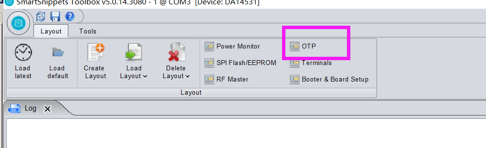
After connecting the chip, you can write and read OTP Image and otphader with simple configuration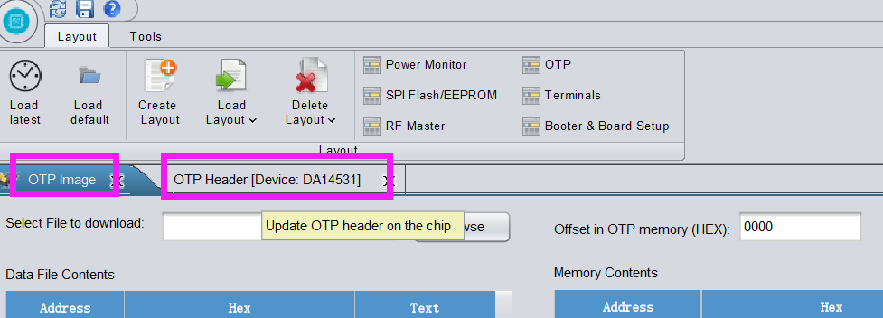
2. Reading and writing OTP in program
Functions related to OTP read / write can be found in the SDK provided by Dialog
In hw_otpc_531.h medium
/** @brief OTP memory base address */
#define MEMORY_OTP_BASE     (0x07F80000)
#if defined (__DA14531__)
    #define MEMORY_OTP_END      (0x07F88000)
#else
    #define MEMORY_OTP_END      (0x07F90000)
#endif

/** @brief OTP memory size (64 KB in DA14585/586 - 32KB in DA14531) */
#define MEMORY_OTP_SIZE         (MEMORY_OTP_END - MEMORY_OTP_BASE)

/// ARM is a 32-bit CPU
#define CPU_WORD_SIZE               (4)

/// ARM is little endian
#define CPU_LE                      (1)
You can see that the OTP start address of DA14531 is 0x07F80000 and the end address is 0x07F88000
The minimum read / write unit each time is 4 bytes, and the small end reads / writes
Library functions provided by SDK:
Read 4 bytes:
/**
 * @brief Read a word from OTP
 * @param[in] cell_offset       The offset of cell to be read in 32 bit words
 * @return otp cell value
 */
uint32_t hw_otpc_word_read(uint32_t cell_offset)
{
    ASSERT_CELL_OFFSET_VALID(cell_offset);

    ASSERT_WARNING_OTP_CLK_ENABLED;

    hw_otpc_enter_mode(HW_OTPC_MODE_READ);
    return *(uint32_t *)(MEMORY_OTP_BASE + HW_OTP_CELL_SIZE * cell_offset);
}
Write 4 bytes:
/**
* @brief Program OTP and verify.
* @param[in] wdata The data to be programmed
* @param[in] cell_offset The offset of cell to be written in 32 bit words
* @return cell true if success or false in fail
*/
bool hw_otpc_word_prog_and_verify(uint32_t wdata, uint32_t cell_offset)
{
ASSERT_CELL_OFFSET_VALID(cell_offset);
ASSERT_WARNING_OTP_CLK_ENABLED;
hw_otpc_word_prog(wdata, cell_offset);
hw_otpc_enter_mode(HW_OTPC_MODE_PVFY);
if (wdata != *(uint32_t *)(MEMORY_OTP_BASE + HW_OTP_CELL_SIZE * cell_offset))
{
return false;
}
hw_otpc_enter_mode(HW_OTPC_MODE_RINI);
if (wdata != *(uint32_t *)(MEMORY_OTP_BASE + HW_OTP_CELL_SIZE * cell_offset))
{
return false;
}
return true;
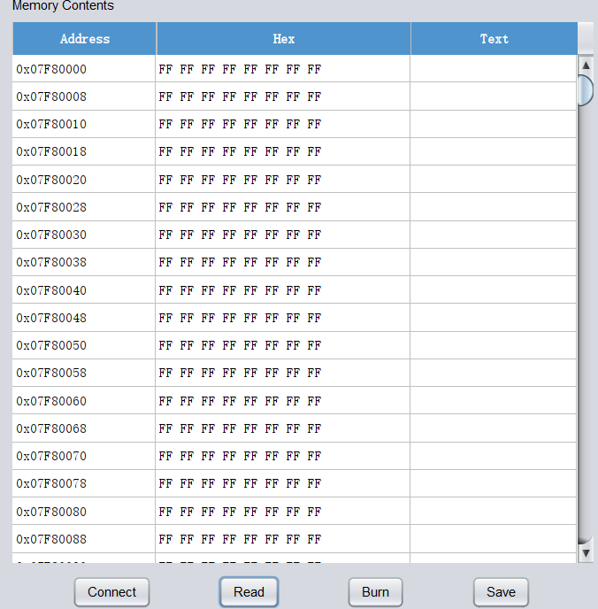
}For example, we need to read the starting position of the last 1KB of OTP, find the place where there is no writing, and start writing data:
The data not written is 0xFFFFFFFF, otherwise it is written and cannot be written again.
//Starting address of parameter area (last 1K), DA14531 32K in total
#define PARA_START_ADDR 	31*256

//From the last 1K of OTP, read 4 bytes by 4 bytes until 0xFFFFFFFFF, and write
void para_set_otp(void)
{
	uint8_t i;
	uint32_t addr_H,addr_L;

	// Initialize OTP controller
	hw_otpc_init();
	hw_otpc_enter_mode(HW_OTPC_MODE_READ);

	for(i=0;i<64;i++)
	{
		addr_H = hw_otpc_word_read(BIO_MAC_START_ADDR+2*i);
		addr_L = hw_otpc_word_read(BIO_MAC_START_ADDR+2*i+1);

		//Find the unwritten block and write the data
		if((addr_H == 0xFFFFFFFF) && (addr_L == 0xFFFFFFFF))
		{
			addr_H = 0x12345678;
			addr_L = 0x87654321;

			//Write data
			hw_otpc_word_prog_and_verify(addr_H,PARA_START_ADDR+2*i);
			hw_otpc_word_prog_and_verify(addr_L,PARA_START_ADDR+2*i+1);

			break;
		}
	}

    //Close OTP
	hw_otpc_disable();
}
It should be noted that the official otpheader is at the end of the last 1K and cannot write data here, otherwise some configuration functions will be affected! Reading OTPImage, you can see that the starting address of the otphader of DA14531 is 0x0787ED0, with a total of 304 bytes.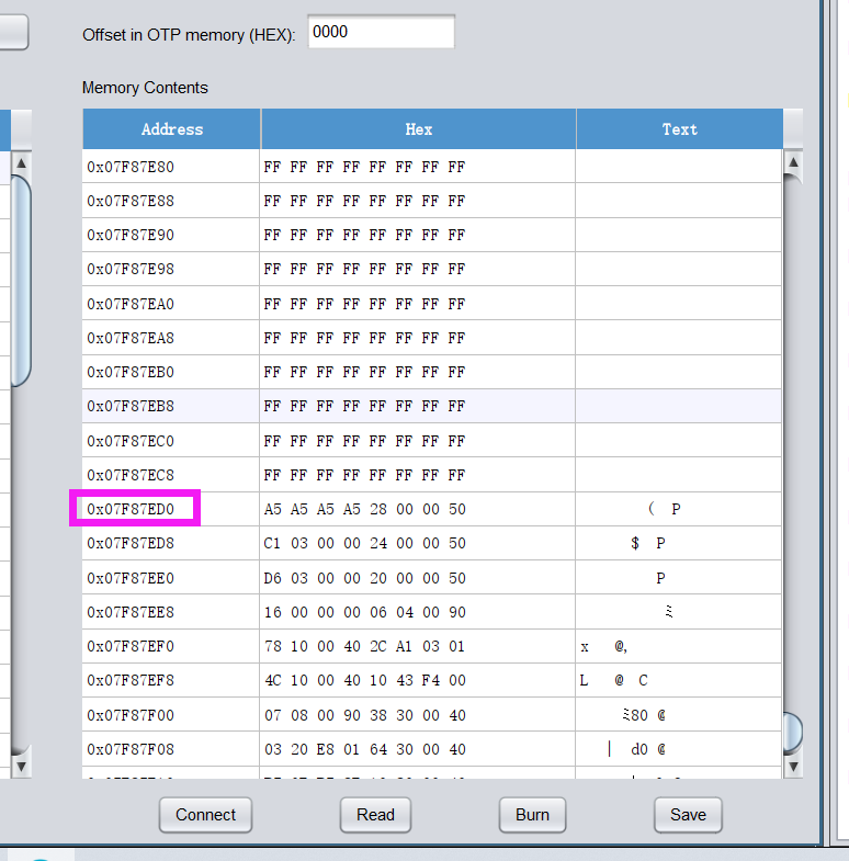
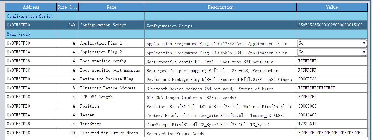
3. The role of the telepreader
(1) Configuration Script, 240 bytes in total, including reserved part.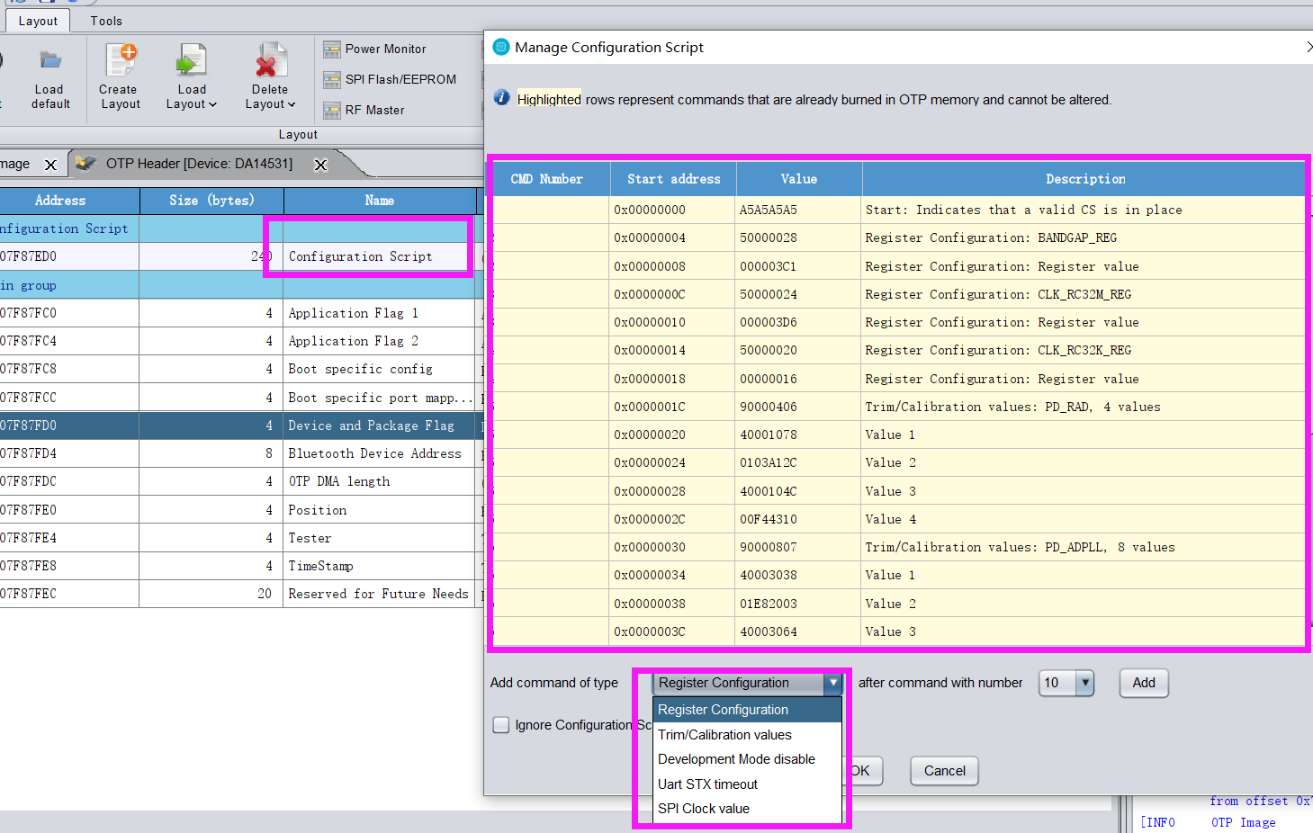
It is used to configure some register parameters. After the SDK is started, the power on chip will read the content of this area and load the register as the value in this area.
In this case, the register of 0x50000024 address (CLK_RC32M_REG) is configured with the value of 0x3D6
(2)Application Flag1,Application Flag2
When YES is selected for writing, the program in OTP will be preferentially enabled to write to RAM after the chip is powered on
(3)Boot specific config
Configure whether to start preferentially from SPI.
(4)Boot specific port mapping
Configure the SPI pin mapping relationship of FLASH startup in boot.
(5)Bluetooth Device Address
Bluetooth MAC address. The value in the address can be enabled as the fixed Bluetooth MAC address of the chip through SDK configuration