preface
On weekdays, blog posts are long or slightly long, but recently I feel that this is not conducive to reading or writing?
-
It's not conducive to writing. It's easy to understand that everyone has their own formal career, goes to work or goes to school, and doesn't have the overall time to write articles. This will lead to a break like me, even for months, and doesn't write for money. Life is already very tired, and it's really not easy to spend a long time writing an article.
-
Not good for watching? When you read your articles, few of them go to browse one by one. Most of them encounter a question? Google or Baidu? If you find the content you want to see, you will get something, or if you don't get anything, quickly change the next one. This is the case in the video industry. Can the article also be changed?
Therefore, things that are beneficial to the author and readers can be changed. That's what today's article is like. Talk about a small knowledge point or a small topic, read it if you are interested, and turn it over if you are not interested.
When the brain can't remember some knowledge points for a long time, you can also search your own articles with keywords, or others. If you search unintentionally, you may get help. The content doesn't need to be very profound, because you think it is profound, others may decide to get started. You feel that getting started will be difficult for others to understand and take what they need.
Problem discussion
Today, I saw in Xilinx's example (waveform example) that the input and output pins of their top-level modules manually instantiate the primitives IBUF and OBUF. I suddenly felt very uncomfortable. Is this really necessary?
The content is as follows, and other logic is omitted.
`timescale 1ns/1ps


module wave_gen (
  input            clk_pin_p,      // Clock input (from pin)
  input            clk_pin_n,      //   - differential pair
  input            rst_pin,        // Active HIGH reset (from pin)

  // RS232 signals
  input            rxd_pin,        // RS232 RXD pin
  output           txd_pin,        // RS232 RXD pin

  // Loopback selector
  input            lb_sel_pin,     // Loopback selector

  // DAC output signals
  output           spi_clk_pin,    // Serial clock
  output           spi_mosi_pin,   // Serial data
  output
  ,   // DAC chip select (active low)
  output           dac_clr_n_pin,  // DAC clear (or reset - active low)

  // LED outputs
  output     [7:0] led_pins         // 8 LED outputs
);


//......

//***************************************************************************
// Code
//***************************************************************************

  // Instantiate input/output buffers
  IBUF IBUF_rst_i0      (.I (rst_pin),      .O (rst_i));
  IBUF IBUF_rxd_i0      (.I (rxd_pin),      .O (rxd_i));
  IBUF IBUF_lb_sel_i0   (.I (lb_sel_pin),   .O (lb_sel_i));

  OBUF OBUF_txd         (.I(txd_o),         .O(txd_pin));
  OBUF OBUF_spi_clk     (.I(spi_clk_o),     .O(spi_clk_pin));
  OBUF OBUF_spi_mosi    (.I(spi_mosi_o),    .O(spi_mosi_pin));
  OBUF OBUF_dac_cs_n    (.I(dac_cs_n_o),    .O(dac_cs_n_pin));
  OBUF OBUF_dac_clr_n   (.I(dac_clr_n_o),  .O(dac_clr_n_pin));


  OBUF OBUF_led_i0      (.I(led_o[0]),      .O(led_pins[0]));
  OBUF OBUF_led_i1      (.I(led_o[1]),      .O(led_pins[1]));
  OBUF OBUF_led_i2      (.I(led_o[2]),      .O(led_pins[2]));
  OBUF OBUF_led_i3      (.I(led_o[3]),      .O(led_pins[3]));
  OBUF OBUF_led_i4      (.I(led_o[4]),      .O(led_pins[4]));
  OBUF OBUF_led_i5      (.I(led_o[5]),      .O(led_pins[5]));
  OBUF OBUF_led_i6      (.I(led_o[6]),      .O(led_pins[6]));
  OBUF OBUF_led_i7      (.I(led_o[7]),      .O(led_pins[7]));

//......
endmodule
If it weren't for the logic written by the robot (stereotype), I really didn't see such an operation in anyone's code?
Of course, I'm not saying that this is wrong. Of course, this is correct. We all know that these two bufs are used to send the input pin into the FPGA (IBUF) and the output signal out of the FPGA output pin (OBUF). Note that I'm talking about the pin here, which corresponds to the external pin, which is called PORT in English.
From this picture:
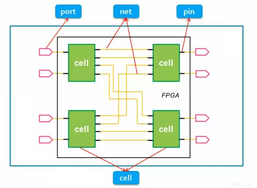
If the black box represents an FPGA, its PIN is PORT; The internal wiring is called NET, and the pins of some internal elements, such as LUT, DFF and DSP, are called pins, and these elements can be called CELL.
Their names have tacit rules.
In other words, it goes further. This is the root cause of the article getting longer as soon as it is written. Sometimes there is a lot of nonsense.
In other words, our more common operation is to use the input pin directly and output the internal signal directly, or reg type or wire type. There is no doubt about this?
The question to be discussed today is: is it necessary to write this?
My view is that since both methods have appeared, one is in the official example and the other is in the logic we usually write, and there is never any problem, both methods are OK. I guess the reasons for this difference should be:
- Code style issues? Most of us are used to saving when we can, that is, we don't have to move unnecessary content. Anyway, the tools will be added to us automatically, which is no problem. Everyone learns from each other, and naturally the mainstream we see is the same.
This may lead to some gj's opposition, saying that we can't leave fate to the compiler. Indeed, for example, when we want to write general logic, we won't manually add some comprehensive attributes to the logic, which may not work on other platforms or other types of FPGA?
However, this is not absolute. Direct processing of input and output signals on any platform like this paper will not cause problems. This is a standard Verilog. There is no such problem. On the contrary, adding explicit IBUF and OBUF primitives may lead to platform incompatibility.
- The difference between machines and people? The machine is not too troublesome. Given some artificial rules, C language and Matlab language can be transformed into Verilog. Do you dare not expect that X FPGA s will send special logic engineers to write Verilog logic manually?
He talked a lot of nonsense.
In fact, for Xilinx platform, according to the normal writing method, the tool will automatically insert such BUF. We know that IBUF is used to drive the internal signal of ordinary input pin (non clock), and OBUF is the internal signal to drive the ordinary output.
The common here is used to distinguish it from the clock.
For IBUFDS and OBUFDS, consistent with the above discussion, the difference only lies in DS, that is, differential signal;
In addition, the BUF used by the clock is usually with G, such as IBUFG, BUFG and OBUFG. We will discuss them next time.
ending
This is the first article in the FPGA logic design essay series. The content is very small, but the length is not only longer. Generally, this problem can be solved in 1000 or hundreds of words. Pay attention to it next time.