After the previous toss, we have designed our own test development board and built a development environment,
Then the functional test is officially started. The test sequence starts from simple, step by step
preface
The following ESP32-C3 function tests are based on the development board designed by ourselves:
Draw an ESP32-C3 development board by yourself (using Lichuang EDA for the first time) (PCB in hand)
The development environment is the official ESP-IDF of Lexin, which is built based on VScode plug-in:
Construction of ESP32-C3 VScode development environment (based on Lexin's official ESP-IDF)
1. ADC sampling sample test
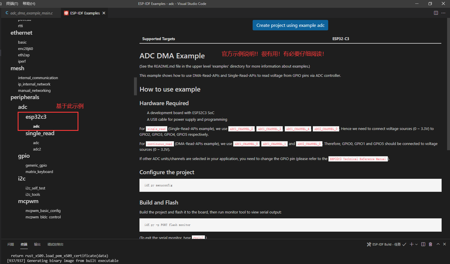
A new ADC sampling project is, of course, based on the official ADC sample code. The way to establish the project is described in the example test section of the above development environment:
1.1 DMA continuous sampling
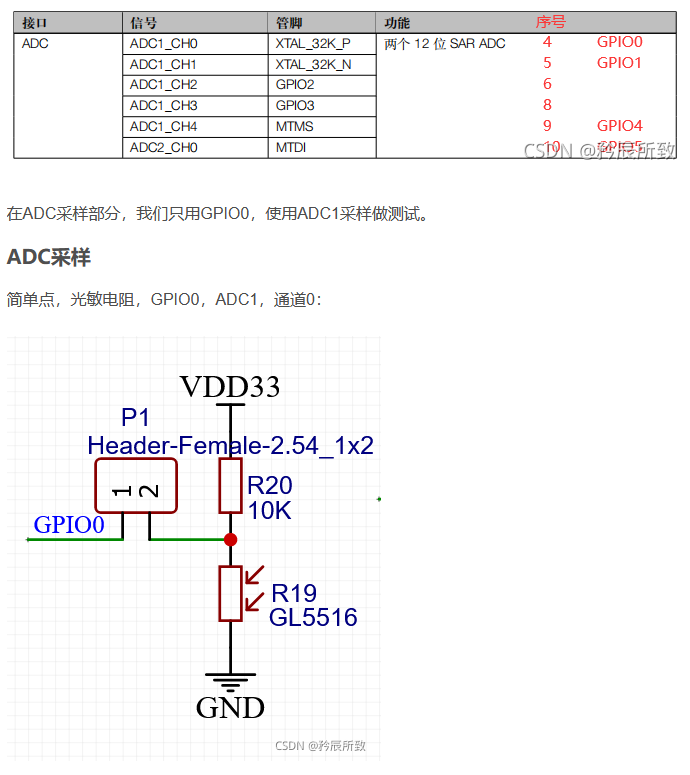
The sample code has two functions, single detection and DMA continuous detection, which are respectively connected to the following channels:
 On the development board, we only reserved one ADC interface, ADC1_CHANNEL_0, a photoresist is connected:
Therefore, the example needs to be slightly modified, mainly for the read function, and only ADC1 is set_ CHANNEL_ 0, as shown below:
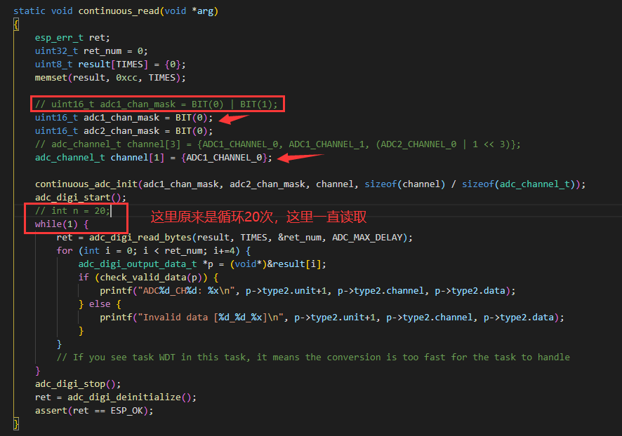
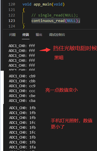
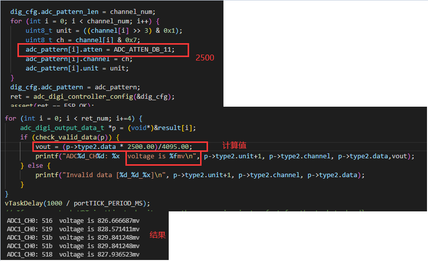
Only continuous is called in the main function_ read(NULL); Function, the test results are as follows:
1.2 single sampling
Single sampling is relatively simple. It is also directly modified in the above example. The modified test code is as follows:
static void single_read(void *arg)
{
    // esp_err_t ret;
    // int adc1_reading[3] = {0xcc};
    int adc1_reading[1] = {0xcc};
    // int adc2_reading[1] = {0xcc};
    float vout;
    // const char TAG_CH[][10] = {"ADC1_CH2", "ADC1_CH3","ADC1_CH4", "ADC2_CH0"};
    const char TAG_CH[1][10] = {"ADC1_CH0"};

    adc1_config_width(ADC_WIDTH_BIT_DEFAULT);
    adc1_config_channel_atten(ADC1_CHANNEL_0, ADC_ATTEN_DB_11);
    // adc1_config_channel_atten(ADC1_CHANNEL_3, ADC_ATTEN_DB_6);
    // adc1_config_channel_atten(ADC1_CHANNEL_4, ADC_ATTEN_DB_0);
    // adc2_config_channel_atten(ADC2_CHANNEL_0, ADC_ATTEN_DB_0);

    // int n = 20;
    // while (n--) {
    while (1) {

        adc1_reading[0] = adc1_get_raw(ADC1_CHANNEL_0);
        // adc1_reading[1] = adc1_get_raw(ADC1_CHANNEL_3);
        // adc1_reading[2] = adc1_get_raw(ADC1_CHANNEL_4);
        vout = (adc1_reading[0] * 2500.00)/4095.00;
        ESP_LOGI(TAG_CH[0], "%x vout mv is %f", adc1_reading[0],vout);


        // for (int i = 0; i < 3; i++) {
        //     ESP_LOGI(TAG_CH[i], "%x", adc1_reading[i]);
        // }
        // ret = adc2_get_raw(ADC2_CHANNEL_0, ADC_WIDTH_BIT_12, &adc2_reading[0]);
        // assert(ret == ESP_OK);
        // ESP_LOGI(TAG_CH[3], "%x", adc2_reading[0]);
        vTaskDelay(500 / portTICK_PERIOD_MS);
    }
}

void app_main(void)
{
    single_read(NULL);
    //continuous_read(NULL);
}
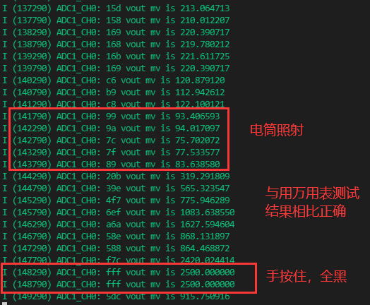
The test results are as follows:
2. Introduction to esp32-c3 ADC
The introduction of ESP32-C3 ADC is described in detail on the official website of Lexin. The official link is as follows:
Description of Lexin's official ESP32-C3 ADC
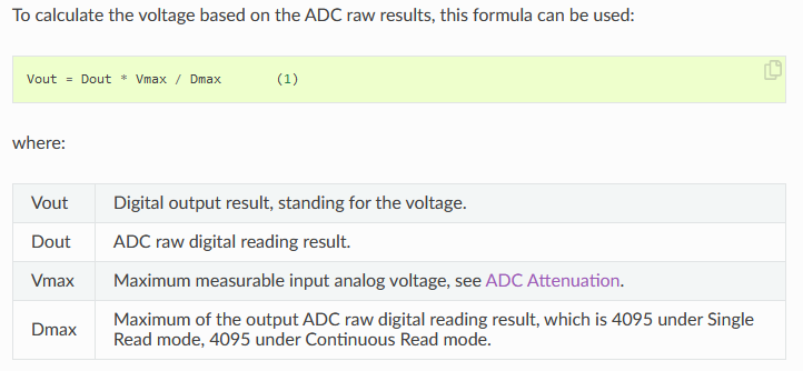
2.1 calculation of actual voltage
For the calculation of actual voltage, there is the following calculation formula:
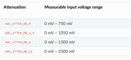
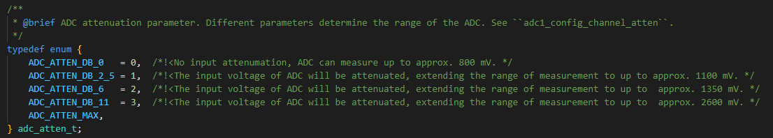
 ADC attachment in Vmax is described in the official document as follows:
Enumeration types are defined in SDK library functions, as follows (there is a difference in values):
In the example, the calculation of the test voltage value according to the formula:
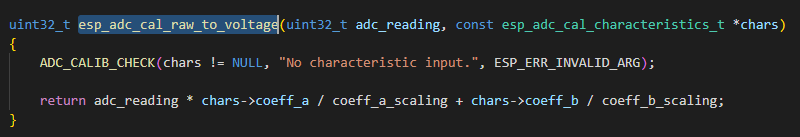
In the library function, there is also the function ESP on voltage conversion_ adc_ cal_ get_ Voltage, where esp_ is called. adc_ cal_ raw_ to_ Voltage mirror calculation:
 The source code is as follows:
/*
esp_adc_cal_characteristics_t The structure is as follows
typedef struct {
    adc_unit_t adc_num;                     /**< ADC number
    adc_atten_t atten;                      /**< ADC attenuation
    adc_bits_width_t bit_width;             /**< ADC bit width
    uint32_t coeff_a;                       /**< Gradient of ADC-Voltage curve
    uint32_t coeff_b;                       /**< Offset of ADC-Voltage curve
    uint32_t vref;                          /**< Vref used by lookup table
    const uint32_t *low_curve;              /**< Pointer to low Vref curve of lookup table (NULL if unused)
    const uint32_t *high_curve;             /**< Pointer to high Vref curve of lookup table (NULL if unused)
} esp_adc_cal_characteristics_t;

The calculation function is as follows:
uint32_t esp_adc_cal_raw_to_voltage(uint32_t adc_reading, const esp_adc_cal_characteristics_t *chars)
{
    ADC_CALIB_CHECK(chars != NULL, "No characteristic input.", ESP_ERR_INVALID_ARG);

    return adc_reading * chars->coeff_a / coeff_a_scaling + chars->coeff_b / coeff_b_scaling;
}

*/
esp_err_t esp_adc_cal_get_voltage(adc_channel_t channel,
                                  const esp_adc_cal_characteristics_t *chars,
                                  uint32_t *voltage)
{
    // Check parameters
    ADC_CALIB_CHECK(chars != NULL, "No characteristic input.", ESP_ERR_INVALID_ARG);
    ADC_CALIB_CHECK(voltage != NULL, "No output buffer.", ESP_ERR_INVALID_ARG);

    int adc_reading;
    if (chars->adc_num == ADC_UNIT_1) {
        //Check if channel is valid on ADC1
        ADC_CALIB_CHECK((adc1_channel_t)channel < ADC1_CHANNEL_MAX, "Invalid channel", ESP_ERR_INVALID_ARG);
        adc_reading = adc1_get_raw(channel);
    } else {
        //Check if channel is valid on ADC2
        ADC_CALIB_CHECK((adc2_channel_t)channel < ADC2_CHANNEL_MAX, "Invalid channel", ESP_ERR_INVALID_ARG);
        if (adc2_get_raw(channel, chars->bit_width, &adc_reading) != ESP_OK) {
            return ESP_ERR_TIMEOUT;     //Timed out waiting for ADC2
        }
    }
    *voltage = esp_adc_cal_raw_to_voltage((uint32_t)adc_reading, chars);
    return ESP_OK;
}
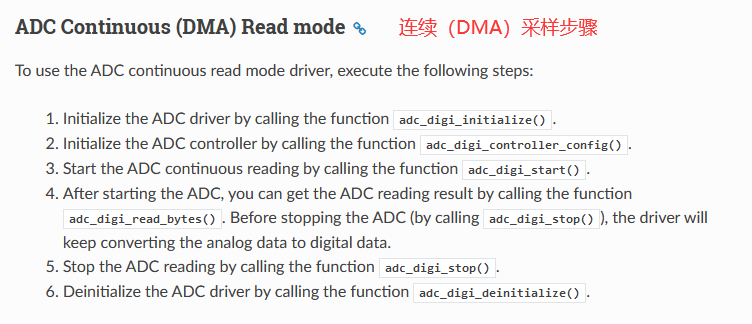
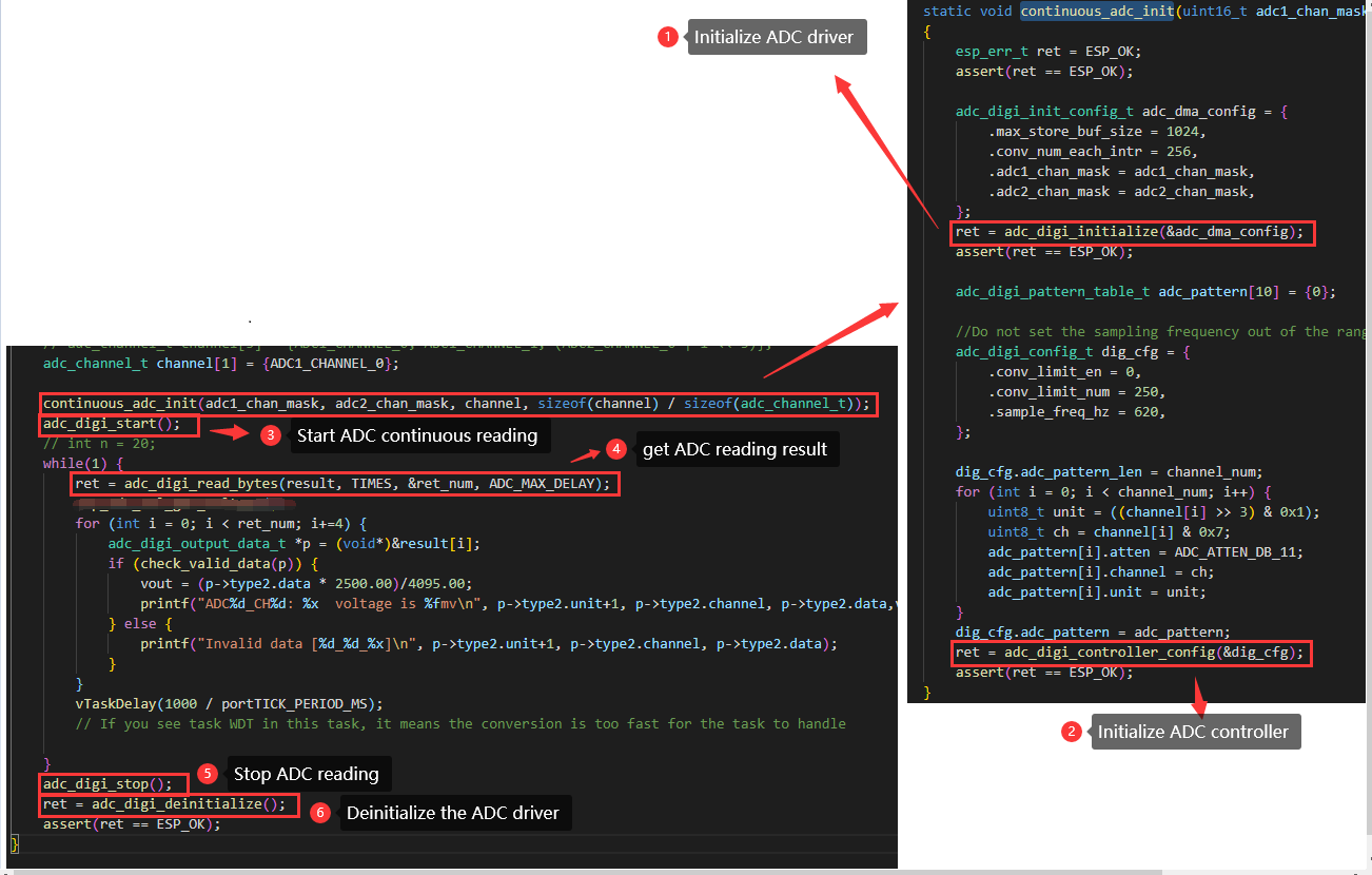
2.2 continuous sampling steps
Description of official continuous sampling steps:
 According to the instructions, let's compare the sample code:
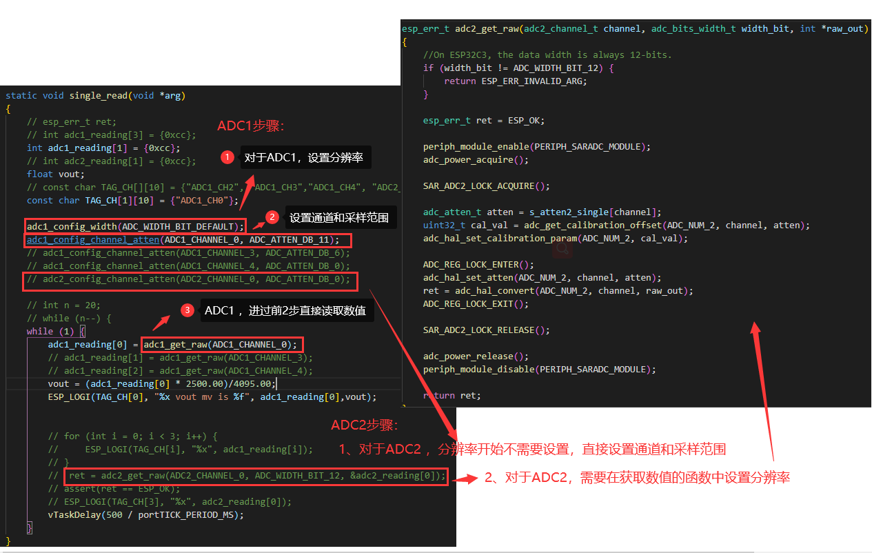
2.3 single step sampling steps
 According to the instructions, let's compare the sample code:
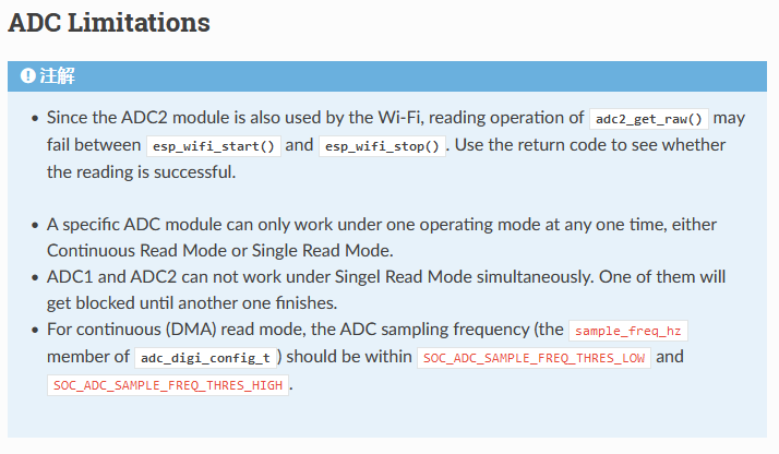
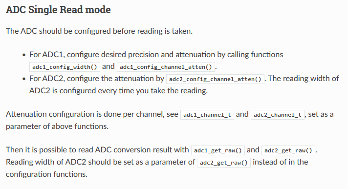
2.4 precautions for ADC use
Or the official manual, briefly explain:
- ADC2 module is also used by WI-FI components, so it is in esp_err_t esp_wifi_start(void) and ESP_ err_ t esp_ wifi_ ADC2 reading between stop (void) functions may not obtain the correct value. In fact, we can try to avoid this in use
- A specific ADC module can only work in one working mode (single and continuous mode) at the same time
- ADC1 and ADC2 cannot work in single read mode at the same time. One of them will be blocked until the other is completed.
- For continuous (DMA) mode, ADC sampling frequency should be within SOC_ADC_SAMPLE_FREQ_THRES_LOW and SOC_ADC_SAMPLE_FREQ_THRES_HIGH range.