1, Experimental purpose
Master the programming and use of finite state machine.
2, Experimental content
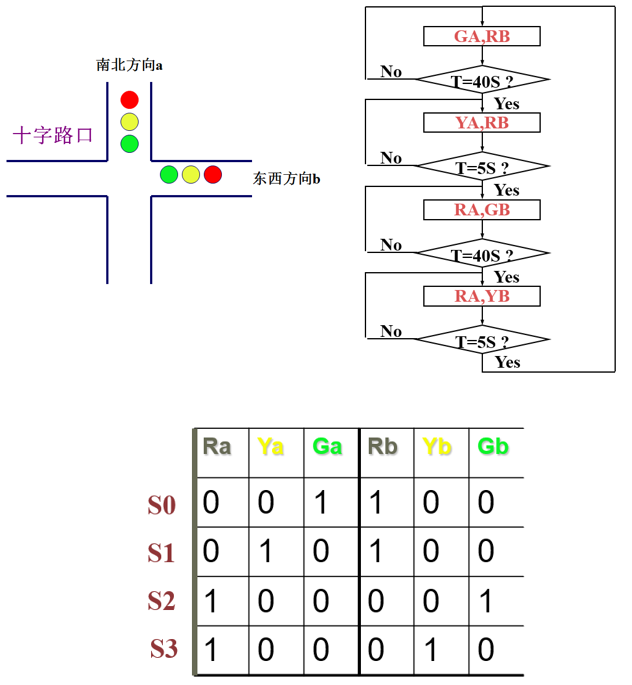
An intersection traffic light controller is designed. There are red lights, yellow lights and green lights in the East-West (b) and North-South (a) directions, with durations of 45, 5 and 40 seconds respectively. Its function is verified by simulation.
3, Experimental design and results
1. Overall design idea: according to the requirements of the topic, it is necessary to use VHDL to describe and design different processes for the functions of "reset and reset", "state definition and transformation", "time definition and control" and "timing". Because the traffic light needs to last 40 seconds, while the yellow light only needs to last 5 seconds, the functions of "time definition and control" and "timing" need to be separated into two parts. Details: attention should be paid to the asynchrony of reset and reset, the four different states of two-way traffic lights, the connection between timing function and state selection, etc. VHDL description code is as follows.
① Introduction and definition:
LIBRARY ieee;
USE ieee.std_logic_1164.ALL;
USE ieee.std_logic_unsigned.ALL;

ENTITY rgy3 is
	port( clk,rst: in std_logic;
		Ra,Rb,Ga,Gb,Ya,Yb: out std_logic);
END rgy3;

Architecture bhv of rgy3 is
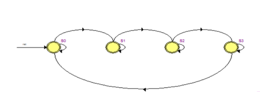
	type state is (S0,S1,S2,S3);
	signal presentstate,nextstate : state;
	signal time40,time5 : std_logic;
	signal rst40,rst5 : std_logic ;
	signal en40,en5 : std_logic ;
	signal tmp40 : std_logic_vector(5 downto 0);
	signal tmp5 : std_logic_vector(2 downto 0);
	begin
② Asynchronous reset reset:
	process(clk,rst)
	begin
	if rst = '1' then presentstate <= S0;
	elsif clk'event and clk='1' then
		presentstate<=nextstate;
	end if;
	end process;
③ 40 second timing:
process(clk,rst40,en40)
	begin
	    if rst = '1' then tmp40<="000000";
	    elsif rst40='1' then tmp40<="000000";
        elsif clk'event and clk='1' then
			if en40='1' then
				if tmp40="100111" then tmp40<="000000";
				else tmp40<=tmp40+1;
		        end if;
			end if;
	    end if;
	 if tmp40="100111" then time40<='1';
	 else time40<='0';
	 end if;
	end process;
④ 5 second timing:
	process(clk,rst5,en5)
	begin
		if rst = '1' then tmp5<="000";
        elsif rst5='1' then tmp5<="000";
        elsif clk 'event and clk='1' then
			if en5='1' then
				if tmp5="100" then tmp5<="000";
				else tmp5<=tmp5+1;
				end if;
			end if;
        end if;
        if tmp5="100" then time5<='1';
        else time5<='0';
        end if;
	end process;
⑤ Connection between time and status:
process(presentstate,time40,time5)
	begin
    case presentstate is
		when S0 => rst40 <='0';en40<='1';rst5<='1';en5<='0';
		if time40= '1' then nextstate<= S1;else nextstate<= S0;
		end if;
		when S1 => rst5 <='0';en5 <='1';rst40<='1';en40<='0';
	  	if time5= '1' then nextstate<= S2;else nextstate<= S1;
		end if;
		when S2 => rst40 <='0';en40<='1';rst5<='1';en5<='0';
		if time40= '1' then nextstate<= S3;else nextstate<= S2;
		end if;
		when S3 => rst5 <='0';en5<='1';rst40<='1';en40<='0';
		if time5= '1' then nextstate<= S0;else nextstate<= S3;
		end if;
	end case;
	end process;
⑥ Status corresponding conversion:
process(presentstate)
	begin
	case presentstate is
         when S0 	=>   Ra<='0'; Ya<= '0'; Ga<='1'; Rb<='1'; Yb<= '0'; Gb<='0';
         when S1 	=>   Ra<='0'; Ya<= '1'; Ga<='0'; Rb<='1'; Yb<= '0'; Gb<='0';
         when S2 	=>   Ra<='1'; Ya<= '0'; Ga<='0'; Rb<='0'; Yb<= '0'; Gb<='1';
         when S3	=>   Ra<='1'; Ya<= '0'; Ga<='0'; Rb<='0'; Yb<= '1'; Gb<='0';
	end case;
	end process;
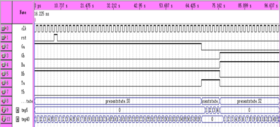
2. Simulation experiment: input: clk, rst, output: Ra, Rb, Ga, Gb, Ya, Yb, and status intermediate output: presentstate, tmp40, tmp5.
3. State machine transition diagram.
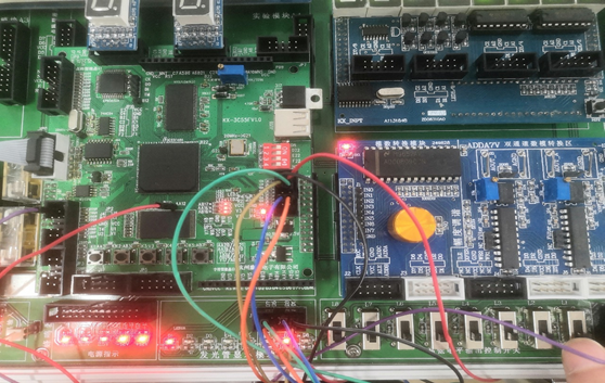
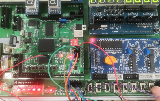
4. Complete the wiring according to the pin configuration, download it to the FPGA chip, and complete the verification on the experimental box. The following figure shows the relevant experimental verification.
4, Experimental thinking and summary
1. The modularization of VHDL description separates the VHDL description of different functions into different processes to realize the "high cohesion and low coupling" of VHDL.
2. It is necessary to specify the transition conditions between different state machines.
3. The state machine is composed of state register and combinational logic circuit. It can transfer the state according to the preset state according to the control signal. It is the control center to coordinate the action of relevant signals and complete specific operations. The traffic signal can be realized by the principle of state machine, because the change state of the signal is limited, each state can be listed, and the switching between States is determined by the counter.