1, Foreword
In OpenGL, everything is in 3D space, while the screen and window are 2D pixel arrays. The process of converting 3D coordinates to 2D coordinates is managed by the graphics rendering pipeline of OpenGL.
The macro aspect of graphics rendering pipeline: it consists of two main parts. The first part transforms 3D coordinates into 2D coordinates, and the second part transforms 2D coordinates into actual colored pixels.
Micro aspect of graphics rendering pipeline: it is divided into several stages (as shown in the figure below): the output of each stage is used as the input of the next stage, and they run their own applet, also known as shader, for each rendering stage on GPU
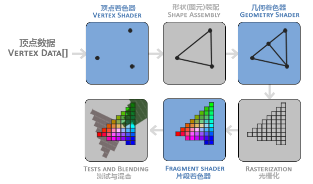
The following will give an inclusive explanation of each stage to give you a general understanding of the working mode of graphics rendering pipeline (for developers, the green part in the above figure has an API to provide flexibility, and other stages are similar to fixed rendering pipeline programming). In modern OpenGL, we must define at least one vertex shader and one fragment shader (because there is no default vertex / fragment shader in GPU, and there are default values in other stages). Before we begin to explain each stage, let's explain: first, we need to have a general knowledge. In OpenGL, the rendering of graphics is made up of points, lines, triangles (in Android), quadrilaterals and polygons. OK, let's start BB
2, Vertex data
Three 3D coordinates are passed in the form of an array as the input of the graphics rendering pipeline to represent a triangle. This array is called vertex data; Vertex data is a collection of a series of vertices. A vertex is a collection of 3D coordinate data. The vertex data is represented by vertex attributes, which can contain any data we want to use, but for simplicity, let's assume that each vertex is composed of only one 3D position and some color values.
float vertices[] = {
	//x,     y,    z,     r,    g,    b,    a
    -0.5f, -0.5f, 0.0f, 123f, 234f, 132f,  0.5f
     0.5f, -0.5f, 0.0f, 123f, 234f, 132f,  0.5f
     0.0f,  0.5f, 0.0f, 123f, 234f, 132f,  0.5f
};
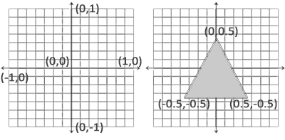
OpenGL processes the 3D coordinates only when they are within the range of - 1.0 to 1.0 on the three axes (x, y and z). It is finally presented on the screen (standardized device coordinates). The standardized device coordinates (as shown in the figure below) will then be transformed into screen space coordinates (in fact, there are various coordinate conversions in the middle). This uses the data you provide through the glViewport function, The viewport transformation is completed (the subsequent blog explains each coordinate space in OpenGL. Don't hurry to look down and have a concept first)
3, Vertex shader
It takes a single vertex as input. The main purpose of vertex shader is to convert 3D coordinates to another kind of 3D coordinates. At the same time, vertex shader allows us to do some basic processing on vertex attributes. It will create memory on the GPU to store our vertex data, configure how OpenGL interprets these memory, and specify how to send them to the graphics card. The vertex shader then processes the number of vertices we specify in memory. We manage this memory through vertex buffer objects (VBO), which stores a large number of vertices in GPU memory.
1. The following code is used to explain the process: vertex shader input
//Generate a VBO object using the glGenBuffers function and a buffer ID
unsigned int VBO;
glGenBuffers(1, &VBO);
//Bind the newly created buffer to GL_ ARRAY_ Buffer target (all subsequent configurations will be bound to the VBO corresponding to the target GL_ARRAY_BUFFER)
glBindBuffer(GL_ARRAY_BUFFER, VBO);
//Copy the previously defined vertex data to the buffered memory
glBufferData(GL_ARRAY_BUFFER, sizeof(vertices), vertices, GL_STATIC_DRAW);
glBufferData Function Description: the first parameter is the type of target buffer; The second parameter specifies the size of the transmitted data (in bytes); The third parameter is the actual data we want to send; The fourth parameter specifies how we want the graphics card to manage the given data. It has three forms:
- GL_STATIC_DRAW: the data will not or will hardly change.
- GL_DYNAMIC_DRAW: the data will be changed a lot.
- GL_STREAM_DRAW: data changes every time it is drawn.
//Tell OpenGL how to parse vertex data
glVertexAttribPointer(0, 3, GL_FLOAT, GL_FALSE, 3 * sizeof(GLfloat), (GLvoid*)0);
//Enable vertex attributes, which are disabled by default
glEnableVertexAttribArray(0);//Here 0 is the value in layout (location = 0)
Description of glVertexAttribPointer function (understood in combination with the description above):
- The first parameter specifies the vertex attributes we want to configure. In * * * 3.2 * * * the following code fragment, the vertex shader uses layout(location = 0) to define the location value of position vertex attribute, which can set the location value of vertex attribute to 0. Because we want to pass the data to this vertex attribute, we pass 0 here.
- The second parameter specifies the size of the vertex attribute. The vertex attribute is a vec3, which consists of three values, so the size is 3.
- The third parameter specifies the type of data. Here is GL_ Float (vec * in glsl is composed of floating-point values).
- The fourth parameter defines whether we want the data to be normalized. If we set it to GL_ If true, all data will be mapped between 0 (or - 1 for signed data) and 1. We set it to GL_FALSE.
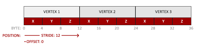
- The fifth parameter is called step, which tells us the interval between successive vertex attribute groups. Since the next group position data is after 3 glfloats, we set the step size to 3 * sizeof(GLfloat). Note that since we know that the array is closely arranged (there is no gap between the two vertex attributes), we can also set it to 0 to let OpenGL determine the specific step size (available only when the values are closely arranged). Once we have more vertex attributes, we must define the interval between each vertex attribute more carefully. We will see more examples later.
- The type of the last parameter is GLvoid *, so we need to do this strange cast. It represents the offset of the starting position of the position data in the buffer. Since the position data is at the beginning of the array, here is 0. We will explain this parameter in detail later.
2. Define a simple GLSL vertex shader (vertexShaderSource):
#version 330 core
layout (location = 0) in vec3 aPos;

void main()
{
    gl_Position = vec4(aPos.x, aPos.y, aPos.z, 1.0);
}
3. Compile shaders
unsigned int vertexShader;
//Create a shader object and reference it with ID
vertexShader = glCreateShader(GL_VERTEX_SHADER);
//The first parameter is the shader object to compile; The second parameter specifies the number of source strings passed. There is only one. The third parameter is the real source code of vertex shader (step 2 above)
glShaderSource(vertexShader, 1, &vertexShaderSource, NULL);
//Compiling shaders
glCompileShader(vertexShader);
//Detects whether the shader was successfully compiled
GLint success;
GLchar infoLog[512];
glGetShaderiv(vertexShader, GL_COMPILE_STATUS, &success);
if(!success)
{
    glGetShaderInfoLog(vertexShader, 512, NULL, infoLog);
    std::cout << "ERROR::SHADER::VERTEX::COMPILATION_FAILED\n" << infoLog << std::endl;
}
Vertex array object (VAO)
The above process binds buffer objects. If it is troublesome to configure all vertex attributes for each object, we must repeat this process every time we draw an object. For this reason, the core pattern of OpenGL requires us to use VAO, so that we can store all these state configurations in an object and restore the state by binding this object. (just like the object pool described in Chapter 1)
The following is the procedure for creating vertex array objects:
// ..:: initialization code (run only once (unless your object changes frequently)):
// 1. Bind VAO
glBindVertexArray(VAO);
// 2. Copy the vertex array to the buffer for OpenGL
glBindBuffer(GL_ARRAY_BUFFER, VBO);
glBufferData(GL_ARRAY_BUFFER, sizeof(vertices), vertices, GL_STATIC_DRAW);
// 3. Set vertex attribute pointer
glVertexAttribPointer(0, 3, GL_FLOAT, GL_FALSE, 3 * sizeof(GLfloat), (GLvoid*)0);
glEnableVertexAttribArray(0);
//4. Unbind the VAO
glBindVertexArray(0);

// ..:: draw (in game loop)::
[...]

// 5. Draw objects
glUseProgram(shaderProgram);//I'll talk about it next
glBindVertexArray(VAO);
someOpenGLFunctionThatDrawsOurTriangle();
glBindVertexArray(0);
4, Element assembly
All vertices output by the vertex shader are used as input, and all points are assembled into the shape of the specified entity. In order to let OpenGL know what our coordinates and color values constitute, OpenGL needs you to specify the rendering type represented by these data. Do we want to render these data into a series of points? A series of triangles? Or just a long line? These prompts are called primitives. Any call of drawing instruction will pass the primitives to OpenGL. Here are some of them: GL_POINTS,GL_TRIANGLES,GL_LINE_STRIP
5, Geometry shader
Geometric shader takes a set of vertices in the form of primitives as input. It can generate new (or other) primitives to generate other shapes (similar to geometric transformation in Mathematics).
6, Rasterization stage
It maps the primitives to the corresponding pixels on the final screen and generates fragments for the fragment shader. Clipping is performed before the clip shader runs. Cropping discards all pixels beyond your view to improve execution efficiency.
7, Clip shader
A fragment in OpenGL is all the data that OpenGL needs to render a pixel. The main purpose of fragment shader is to calculate the final color of a pixel, which is where all OpenGL advanced effects are produced. Generally, fragment shaders contain data of 3D scene (such as lighting, shadow, light color, etc.), which can be used to calculate the color of final pixels.
1. Define clip shaders
#version 330 core

out vec4 color;

void main()
{
    color = vec4(1.0f, 0.5f, 0.2f, 1.0f);
}
The fragment shader only needs an output variable, which is a 4-component vector that represents the final output color
2. Compile fragment shaders
GLuint fragmentShader;
fragmentShader = glCreateShader(GL_FRAGMENT_SHADER);
glShaderSource(fragmentShader, 1, &fragmentShaderSource, null);
glCompileShader(fragmentShader);
Similar to vertex shader, except we use GL_FRAGMENT_SHADER constant as shader type
3. Link generator object
//1. Create program object
GLuint shaderProgram;
shaderProgram = glCreateProgram();
//2. Attach the previously compiled shader to the program object
glAttachShader(shaderProgram, vertexShader);
glAttachShader(shaderProgram, fragmentShader);
//3. Link
glLinkProgram(shaderProgram);
//4. Check whether the link is successful
glGetProgramiv(shaderProgram, GL_LINK_STATUS, &success);
if(!success) {
    glGetProgramInfoLog(shaderProgram, 512, NULL, infoLog);
  ...
}
//5. Activate program object
glUseProgram(shaderProgram);
//6. Delete shader object
glDeleteShader(vertexShader);
glDeleteShader(fragmentShader);
At this point, we have sent the input vertex data to the GPU and instructed the GPU how to process it in the vertex and fragment shaders
8, Alpha testing and blending
This stage detects the corresponding depth (and Stencil) values of the segment, uses them to judge whether the pixel is in front of or behind other objects, and determines whether it should be discarded. This phase also checks the alpha value (which defines the transparency of an object) and blends the object. Therefore, even if the output color of one pixel is calculated in the fragment shader, the final pixel color may be completely different when rendering multiple triangles.
// Setup OpenGL options
glEnable(GL_DEPTH_TEST);
glClear(GL_COLOR_BUFFER_BIT | GL_DEPTH_BUFFER_BIT);
reference
Learnopungl Chinese official website