polygon
(1) Both sides of the polygon and how it is drawn.
Although we have not really used three-dimensional coordinates to draw drawings, it is necessary to establish some three-dimensional concepts.
From a 3D perspective, a polygon has two faces. Each face can be drawn in different ways: fill, draw only edge contours, and draw only vertices. Fill is the default.
You can set different ways for two faces.
glPolygonMode(GL_FRONT, GL_FILL); / / set the front face as the filling method
glPolygonMode(GL_BACK, GL_LINE); / / set the reverse side as the edge drawing method
glPolygonMode(GL_FRONT_AND_BACK, GL_POINT); // Sets how both sides are vertex drawn
(2) Reverse
The general convention is that "the face whose vertices appear on the screen in counterclockwise order" is "positive", and the other face is "negative".
But there are some special surfaces. For example, "Mabius belt" (please Google it yourself) can be represented by "front" or "back".
You can exchange the concepts of "positive" and "negative" through the glFrontFace function.
glFrontFace(GL_CCW); / / set CCW direction to "front", CCW is counter clockwise, CounterClockWise
glFrontFace(GL_CW); / / set the CW direction to "front", CW is ClockWise, ClockWise
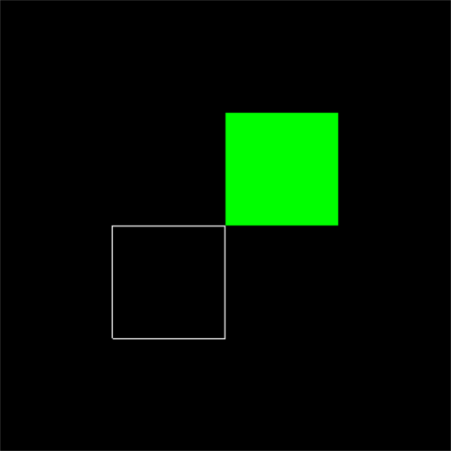
The following is an example program. Please replace the myDisplay function in the first lesson with it, modify glFrontFace(GL_CCW) to glFrontFace(GL_CW), and observe the change of the result.
void myDisplay(void)
{
    glClear(GL_COLOR_BUFFER_BIT);
    glPolygonMode(GL_FRONT, GL_FILL); // Set the front face to fill mode
    glPolygonMode(GL_BACK, GL_LINE);   // Set the reverse side to linear mode
    glFrontFace(GL_CW);               // Set the clockwise direction as the front, and the default is counterclockwise_ CCW
    glBegin(GL_POLYGON);               // Draw a square counterclockwise, at the bottom left
    glVertex2f(-0.5f, -0.5f);
    glVertex2f(0.0f, -0.5f);
    glVertex2f(0.0f, 0.0f);
    glVertex2f(-0.5f, 0.0f);
    glEnd();
    glColor3f(0.0f, 1.0f, 0.0f);
    glBegin(GL_POLYGON);               // Draw a square clockwise, at the top right
    glVertex2f(0.0f, 0.0f);
    glVertex2f(0.0f, 0.5f);
    glVertex2f(0.5f, 0.5f);
    glVertex2f(0.5f, 0.0f);
    glEnd();
    glFlush();
}
(3) Cull polygon surface
In three-dimensional space, although a polygon has two faces, we can't see those polygons on the back. Although some polygons are front, they are obscured by other polygons. If we treat invisible polygons as visible polygons, it will undoubtedly reduce our efficiency in processing graphics. In this case, unnecessary faces can be eliminated.
First, use glEnable(GL_CULL_FACE); To start the culling function (you can turn it off by using glDisable(GL_CULL_FACE))
Then, use glCullFace to cull.
The parameter of glCullFace can be GL_FRONT,GL_BACK or GL_FRONT_AND_BACK, which means to eliminate the polygons on the front, the back and the positive and negative sides respectively.
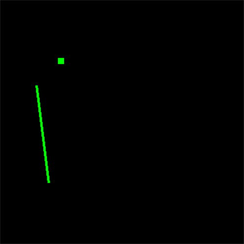
Note: culling only affects polygons, not points and lines. For example, after using glCullFace(GL_FRONT_AND_BACK), all polygons will be eliminated, so all you see are points and lines.
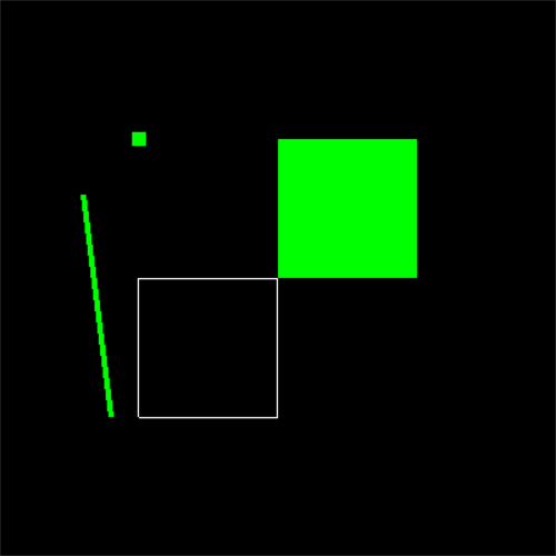
Next, draw two faces, a line and a point to test:
void myDisplay(void)
{
    glClear(GL_COLOR_BUFFER_BIT);
    glPolygonMode(GL_FRONT, GL_FILL); // Set the front face to fill mode
    glPolygonMode(GL_BACK, GL_LINE);   // Set the reverse side to linear mode
    glFrontFace(GL_CW);               // Set the clockwise direction as the front, and the default is counterclockwise_ CCW
    glBegin(GL_POLYGON);               // Draw a square counterclockwise, at the bottom left
        glVertex2f(-0.5f, -0.5f);
        glVertex2f(0.0f, -0.5f);
        glVertex2f(0.0f, 0.0f);
        glVertex2f(-0.5f, 0.0f);
    glEnd();


    glColor3f(0.0f, 1.0f, 0.0f);
    glBegin(GL_POLYGON);               // Draw a square clockwise, at the top right
        glVertex2f(0.0f, 0.0f);
        glVertex2f(0.0f, 0.5f);
        glVertex2f(0.5f, 0.5f);
        glVertex2f(0.5f, 0.0f);
    glEnd();

    //Draw a point and test it. Removing faces will not affect points and lines
    glPointSize(10);
    glBegin(GL_POINTS);
    glVertex2f(-0.5f, 0.5f);
    glEnd();

    glLineWidth(4);
    glBegin(GL_LINES);
    glVertex2f(-0.7f, 0.3f);
    glVertex2f(-0.6f, -0.5f);
    glEnd();

    glEnable(GL_CULL_FACE);//Start culling function (it can be turned off by using glDisable(GL_CULL_FACE))
    glCullFace(GL_FRONT_AND_BACK);
    glFlush();
}
The picture at the beginning is like this. The effect after elimination is on the right
(4) hollowed out polygon
Straight lines can be drawn as dashed lines, while polygons can be hollowed out.
First, use glEnable(GL_POLYGON_STIPPLE); To start the hollowed out mode (it can be turned off by using glDisable(GL_POLYGON_STIPPLE).
Then, use glpolygonstepple to set the style of hollowing out.
void glPolygonStipple(const GLubyte *mask);
The parameter mask points to a space with a length of 128 bytes, which indicates how a 32 * 32 rectangle should be hollowed out. Where: the first byte indicates whether the 8 pixels at the bottom left are hollowed out from left to right (or right to left, which can be modified) (1 indicates no hollowing out, display the pixel; 0 indicates hollowing out, display the color behind), and the last byte indicates whether the 8 pixels at the top right are hollowed out.
However, if we directly define this mask array, like this:
static GLubyte Mask[128] =
{
     0x00, 0x00, 0x00, 0x00,    //   This is the bottom line
     0x00, 0x00, 0x00, 0x00,
     0x03, 0x80, 0x01, 0xC0,    //   hemp
     0x06, 0xC0, 0x03, 0x60,    //   Annoyed
     0x04, 0x60, 0x06, 0x20,    //   of
     0x04, 0x30, 0x0C, 0x20,    //   first
     0x04, 0x18, 0x18, 0x20,    //   beginning
     0x04, 0x0C, 0x30, 0x20,    //   turn
     0x04, 0x06, 0x60, 0x20,    //   ,
     0x44, 0x03, 0xC0, 0x22,    //   no
     0x44, 0x01, 0x80, 0x22,    //   build
     0x44, 0x01, 0x80, 0x22,    //   Discuss
     0x44, 0x01, 0x80, 0x22,    //   send
     0x44, 0x01, 0x80, 0x22,    //   use
     0x44, 0x01, 0x80, 0x22,
     0x44, 0x01, 0x80, 0x22,
     0x66, 0x01, 0x80, 0x66,
     0x33, 0x01, 0x80, 0xCC,
     0x19, 0x81, 0x81, 0x98,
     0x0C, 0xC1, 0x83, 0x30,
     0x07, 0xE1, 0x87, 0xE0,
     0x03, 0x3F, 0xFC, 0xC0,
     0x03, 0x31, 0x8C, 0xC0,
     0x03, 0x3F, 0xFC, 0xC0,
     0x06, 0x64, 0x26, 0x60,
     0x0C, 0xCC, 0x33, 0x30,
     0x18, 0xCC, 0x33, 0x18,
     0x10, 0xC4, 0x23, 0x08,
     0x10, 0x63, 0xC6, 0x08,
     0x10, 0x30, 0x0C, 0x08,
     0x10, 0x18, 0x18, 0x08,
     0x10, 0x00, 0x00, 0x08    // This is the top line
};
Such a pile of data is very lack of intuition. We need to analyze it very hard to find that it represents a fly.
If such data is saved as pictures and edited with special tools, it will obviously be much more convenient. Here's how to do this.
First, create a new picture with the brush program provided by Windows, named mask BMP, note that "monochrome bitmap" should be selected when saving. In the image - > Properties dialog box, set the height and width of the picture to 32.
Look at the picture with a magnifying glass and edit it. Black corresponds to binary zero (hollowed out), and white corresponds to binary one (not hollowed out). Save after editing.
Then, you can use the following code to get the Mask array.
static GLubyte Mask[128];
FILE *fp;
fp = fopen("mask.bmp", "rb");
if( !fp )
exit(0);
//Move the file pointer to this position so that reading sizeof(Mask) bytes again will encounter the end of the file
//Note that although - (int)sizeof(Mask) is not a good way to write it, it is indeed correct and effective here
//If you write - sizeof(Mask) directly, because sizeof obtains an unsigned number, there will be a problem taking the minus sign
if( fseek(fp, -(int)sizeof(Mask), SEEK_END) )
exit(0);
//Read sizeof(Mask) bytes to Mask
if( !fread(Mask, sizeof(Mask), 1, fp) )
exit(0);
fclose(fp);
OK, now please edit an image as a mask, and use the above method to obtain the mask array. After running, observe the effect.
Note: factor factor can be set when drawing dotted lines, but factor cannot be set for hollowing out polygons. Please use the mouse to change the size of the window and observe the change of hollowing effect.
#include <GL/freeglut.h>
//Originally, OpenGL programs generally include < GL / GL h> And < GL / Glu h>
//However, these two files have been automatically included in the header file of GLUT, so they do not need to be included again.
#include <iostream>
using namespace std;
//static GLubyte Mask[128] =
//{
// 0x00, 0x00, 0x00, 0x00, / / this is the bottom line
// 0x00, 0x00, 0x00, 0x00,
// 0x03, 0x80, 0x01, 0xC0, / / hemp
// 0x06, 0xC0, 0x03, 0x60, / / trouble
// 0x04, 0x60, 0x06, 0x20, / / Yes
// 0x04, 0x30, 0x0C, 0x20, / / initial
// 0x04, 0x18, 0x18, 0x20, / / start
// 0x04, 0x0C, 0x30, 0x20, / / chemical
// 0x04, 0x06, 0x60, 0x20, // ,
// 0x44, 0x03, 0xC0, 0x22, / / no
// 0x44, 0x01, 0x80, 0x22, / / build
// 0x44, 0x01, 0x80, 0x22, / / discussion
// 0x44, 0x01, 0x80, 0x22, / / enable
// 0x44, 0x01, 0x80, 0x22, / / use
// 0x44, 0x01, 0x80, 0x22,
// 0x44, 0x01, 0x80, 0x22,
// 0x66, 0x01, 0x80, 0x66,
// 0x33, 0x01, 0x80, 0xCC,
// 0x19, 0x81, 0x81, 0x98,
// 0x0C, 0xC1, 0x83, 0x30,
// 0x07, 0xE1, 0x87, 0xE0,
// 0x03, 0x3F, 0xFC, 0xC0,
// 0x03, 0x31, 0x8C, 0xC0,
// 0x03, 0x3F, 0xFC, 0xC0,
// 0x06, 0x64, 0x26, 0x60,
// 0x0C, 0xCC, 0x33, 0x30,
// 0x18, 0xCC, 0x33, 0x18,
// 0x10, 0xC4, 0x23, 0x08,
// 0x10, 0x63, 0xC6, 0x08,
// 0x10, 0x30, 0x0C, 0x08,
// 0x10, 0x18, 0x18, 0x08,
// 0x10, 0x00, 0x00, 0x08 / / this is the top line
//};
void myDisplay(void)
{
static GLubyte Mask[128];
FILE* fp;
fp = fopen("mask.bmp", "rb");
if (!fp)
exit(0);
if (fseek(fp, -(int)sizeof(Mask), SEEK_END))
exit(0);
if (!fread(Mask, sizeof(Mask), 1, fp))
exit(0);
fclose(fp);
glClear(GL_COLOR_BUFFER_BIT);
glEnable(GL_POLYGON_STIPPLE);//Start hollowed out mode (it can be turned off by using glDisable(GL_POLYGON_STIPPLE).
glPolygonStipple(Mask);
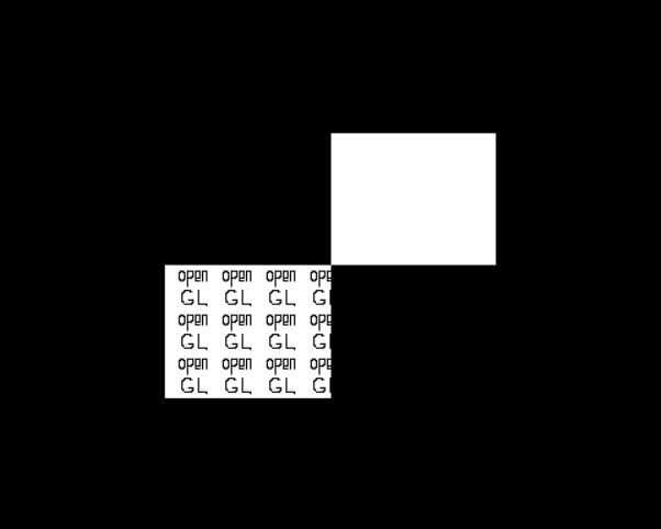
glRectf(-0.5f, -0.5f, 0.0f, 0.0f); // Draw a hollowed out square at the bottom left
glDisable(GL_POLYGON_STIPPLE);
glRectf(0.0f, 0.0f, 0.5f, 0.5f); // Draw a square with no hollowed out effect on the upper right
glFlush();
}
int main(int argc, char* argv[])
{
glutInit(&argc, argv); //To initialize GLUT, this function must be called once other GLUT is used.
//The format is rigid. Generally, just copy this sentence glutinit (& argc, argv).
glutInitDisplayMode(GLUT_RGB | GLUT_SINGLE);//Set the display mode, where GLUT_RGB means to use RGB color,
//Corresponding to it is GLUT_INDEX (indicates that the index color is used).
//GLUT_SINGLE indicates that a single buffer is used, and GLUT also corresponds to it_ Double (use double buffering).
glutInitWindowPosition(0, 0);
glutInitWindowSize(400, 400);
glutCreateWindow("first OpenGL program");//Create a window based on the previously set information. Parameter will be used as the title of the window.
//Note: after the window is created, it does not appear on the screen immediately. You need to call glutMainLoop to see the window.
glutDisplayFunc(&myDisplay);//Call display function
glutMainLoop();//Continuous cycle
return 0;
}The results are displayed in the left figure, and some figures are mask images

Summary
This lesson learned some details of drawing geometry:
1. Points can be sized.
2. The width of the straight line can be set; You can draw a straight line as a dotted line.
3. The drawing methods of two faces of a polygon can be set separately; In three-dimensional space, invisible polygons can be eliminated; Fill polygons can be drawn in a hollowed out style.
Understanding these details will make us more handy in some image rendering.
In addition, it is sometimes more convenient to write some data into files outside the program and edit it with special tools.