0 Introduction
You have just started learning SLAM for nearly a month, but you don't know much about the theoretical derivation. So you have developed a simple demo of 2D LiDAR SLAM on matlab to understand the complete process of SLAM.
(1) Data source: 2D laser SLAM data from Deutsches Museum, Germany, linked as follows:
Public Data - Cartographer ROS documentationgoogle-cartographer-ros.readthedocs.io
(2)SLAM process display (small video below stamp)
<iframe frameborder="0" allowfullscreen="" src="https://www.zhihu.com/video/1050063244621930496" style="display: block; width: 688px; height: 387px;"></iframe>
2D LiDAR SLAM
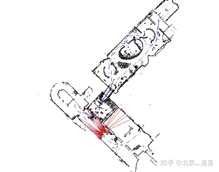
(3) SLAM effect obtained by demo:
SLAM effects (including path, current position, raster map)
1 Data preparation and parameter settings
1.1 2DLiDAR dataset preparation
The provided 2DLiDAR dataset'b0-2014-07-11-10-58-16.bag'will be converted to a matlab.mat data file, which includes 5522 batches of scanned data with 1079 intensity points per scan.The following:

1.2 Sensor parameter settings for LiDAR
Includes: scan angle range, scan angle interval, number of scan points, scan time, number of bundles in one scan, etc.(See source code for details)
1.3 Posture and Map Parameter Settings
These include the actual length of the raster map cell size, how many times the robot moves to update the map and posture, the initial posture, and so on.(See source code for details)
2 Procedure flow and thinking
2.1 Data preparation and parameter settings.
2.2 Traverse through each batch of scanned data (5522 batches), and for a batch of scanIdx proceed as follows:
(1) Calculate the local Cartesian coordinates (ReadAScan.m) of the batch scanned data (using the mobile robot as the origin).
(2) Determine whether the batch is the first batch?If so, initialize (Initialize.m); if not, proceed directly to the next step.
(3) The global coordinates (Transform.m and ExtractLocalMap.m) of the current scanned data points are derived from the local coordinates and the current position of the batch scanned data (actually this is a collection of 1079 points).
---------Insert an explanation---------
Local coordinates: The two-dimensional coordinates of the data point in space obtained from a scan in which the spatial (two-dimensional) location of the robot is the origin.
Global coordinates: The two-dimensional coordinates of any batch of scanned data are described using the initial position of the robot as the origin.
-------------------------------------
(4) Construct the scanned raster map (OccuGrid.m) with the global coordinates of the data.For example:
(5) Predict the next position (position and posture are x-coordinate, y-coordinate, three-dimensional vector of rotation angle theta).
*The prediction method is: if the current position is the initial position, the predicted next position = the current position; otherwise, the predicted next position = the current position + (current position - previous position).
(6) Optimize the predicted next position based on the current position raster map (FastMatch.m).
*The idea is to make some small adjustments (fine adjustments to x, y, theta) in the next position of the prediction; to predict the next position after one adjustment, use the scan data of the next position to build the raster map of the next position; the overlap between the raster map of the following position and the raster map of the current position is used as the objective function to get the maximum value of the objective function;The next position obtained is the optimized one.(The result must be a global optimal solution, because only a limited number of fine adjustments have been made to the next position based on the original prediction)
For example, the predicted posture is [-16.5250; -0.7344; -3.9177]; optimized posture is [-16.5250; -0.7156; -3.9057].
(7) Determine if the difference between the next position and the current position reaches the set threshold?If so, update (AddAKeyScan.m); otherwise, do not update.
The update step is to determine if there is a big difference between the predicted next position and the current position on either x or y or theta?If so, it is judged that the prediction is incorrect, then the current posture = the previous posture (so saving the previous posture is required) and the traversal starts again from the previous posture; otherwise, if the next posture is considered correct, add the global coordinates of the dataset of the next posture to the global map.
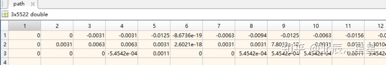
(8) Merge the next position into the path.
Therefore, the path is a set of postures [x;y;theta], as follows:
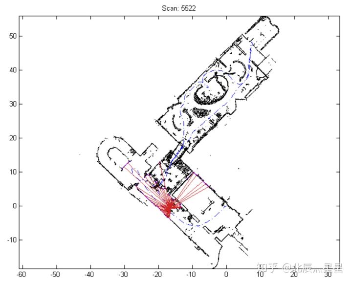
(9) Drawing (global map, path, current position) (PlotMap.m)
The result of the final drawing is as follows:
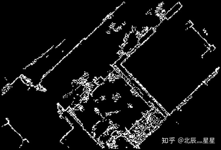
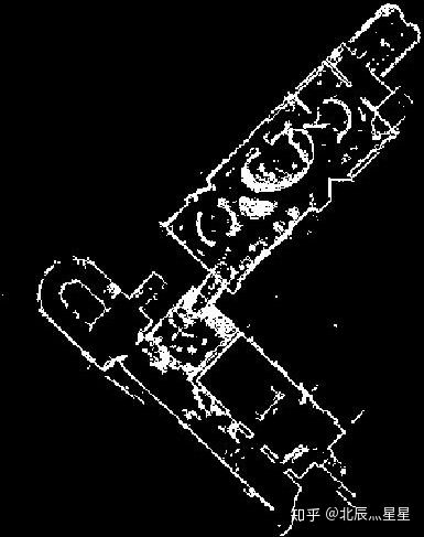
In addition, the resulting raster map is as follows:
3 MATLAB source code (with detailed comments)
Place the following functions under the path and run main.m directly.
**Add that horizental_lidar.mat can be downloaded with the following weblink stamped and placed under the path:
https://pan.baidu.com/s/1KDb9zO1dDlvJq-ut9Xj0gg
----------------------
Cited from:
https://github.com/meyiao/LaserSLAM?files=1
----------------------
List of functions:
(1)main.m
(2)SetLidarParameters.m
(3)ReadAScan.m
(4)Initializ.m
(5)Transform.m
(6)ExtractLocalMap.m
(7)OccuGrid.m
(8)FastMatch.m
(9)AddAKeyScan.m
(10)PlotMap.m
(11)DiffPose.m
----------------------
(1)main.m
%Principal function
clear; close all; clc;
cfig = figure(1);
%cfig = figure('Position', [10,10,1280,1080]);
% Sensor parameters for lidar
lidar = SetLidarParameters();
% Map parameters
borderSize      = 1;            % Boundary Size
pixelSize       = 0.2;          % The edge length of a cell of a raster map corresponds to the actual distance pixelSize rice(Set here to 0.2 rice)
miniUpdated     = false;        %
miniUpdateDT    = 0.1;          % Company m  If the robot is in x Direction or y Move in direction beyond miniUpdateDT Update your posture
miniUpdateDR    = deg2rad(5);   % Company rad If the robot rotates more than miniUpdateDR Update your posture
% If the robot moves 0 from the last key scan.1 With meters or 5 degrees rotation, we'll add a new key to scan and update the map

% Scan Matching Parameters
fastResolution  = [0.05; 0.05; deg2rad(0.5)]; % [m; m; rad]Resolution
bruteResolution = [0.01; 0.01; deg2rad(0.1)]; % not used

% Reading lidar data
lidar_data = load('horizental_lidar.mat');
N = size(lidar_data.timestamps, 1);%Number of scans(Control the number of loops below)

% Construct an empty global map
map.points = [];%Atlas of Points
map.connections = [];
map.keyscans = [];%keyscans Save scanned data for the current correct posture Return to the nearest previous posture recalculation if the predicted next posture is incorrect
pose = [0; 0; 0];%Initial position is(x=0,y=0,theta=0)
path = pose;%Positions juxtaposed to form a path


%Whether to save the drawing process as a video
saveFrame=0;
if saveFrame==1
    % Video Save File Definition and Opening
    writerObj=VideoWriter('SLAMprocess.avi');  % Define a video file to store the animation
    open(writerObj);                    % Open the video file
end

% Here we go!!!!!!!!!!!!!!!!!!!!
for scanIdx = 1 : 1 : N
    disp(['scan ', num2str(scanIdx)]);

    % Get the current scan [x1,y1; x2,y2; ...]
    %time = lidar_data.timestamps(scanIdx) * 1e-9;%Time set to every e-9 Scan once
    scan = ReadAScan(lidar_data, scanIdx, lidar, 24);%Get the local Cartesian coordinates of the scanned data

    % Initialize if first scan
    if scanIdx == 1
        map = Initialize(map, pose, scan);%Scan data scan Coordinates pass through position pose Convert to Global Map map coordinate
        miniUpdated = true;
        continue;
    end

    % 1. If we did it in the last step mini Update, we will update the local point set map and the local raster map (coarse)
    % 1. If we executed a mini update in last step, we shall update the local points map and local grid map (coarse)
    if miniUpdated
        localMap = ExtractLocalMap(map.points, pose, scan, borderSize);%Get the global coordinates of the current scan
        gridMap1 = OccuGrid(localMap, pixelSize);%From point set localMap The raster cell size corresponds to the actual length to pixelSize Create Occupancy Raster Map
        gridMap2 = OccuGrid(localMap, pixelSize/2);%From point set localMap The raster cell size corresponds to the actual length to pixelSize/2 Create Occupancy Raster Map
    end

    % 2. Predicting current position using a constant velocity motion model(Predict the next state from this state by using the process from the previous state to this state as the process from this state to the next state)
    if scanIdx > 2
        pose_guess = pose + DiffPose(path(:,end-1), pose);%Predict Next Posture=Current Posture+(Difference between current position and previous position) pose Is a global coordinate
    else
        pose_guess = pose;
    end

    % 3. Quick Match
    if miniUpdated
        [pose, ~] = FastMatch(gridMap1, scan, pose_guess, fastResolution);%Optimize the predicted next position based on the current raster map
    else
        [pose, ~] = FastMatch(gridMap2, scan, pose_guess, fastResolution);
    end

    % 4. Predict the next position using higher resolution and refinement
    % gridMap = OccuGrid(localMap, pixelSize/2);
    [pose, hits] = FastMatch(gridMap2, scan, pose, fastResolution/2);%Return to the next position for further updates pose

    % If the robot moves a certain distance, execute mini To update
    dp = abs(DiffPose(map.keyscans(end).pose, pose));%Difference between two positions
    if dp(1)>miniUpdateDT || dp(2)>miniUpdateDT || dp(3)>miniUpdateDR
        miniUpdated = true;
        [map, pose] = AddAKeyScan(map, gridMap2, scan, pose, hits,...
                        pixelSize, bruteResolution, 0.1, deg2rad(3));
    else
        miniUpdated = false;
    end

    path = [path, pose]; %Put your current position pose Merge into Path path

    % ===== Loop Closing =========================================
    % if miniUpdated
    %     if TryLoopOrNot(map)
    %         map.keyscans(end).loopTried = true;
    %         map = DetectLoopClosure(map, scan, hits, 4, pi/6, pixelSize);
    %     end
    % end
    %----------------------------------------------------------------------

    % Mapping
    if mod(scanIdx, 30) == 0%Draw every 30 steps
        PlotMap(cfig, map, path, scan, scanIdx);
        %Get a video frame and save it as a video
        if saveFrame==1
            frame = getframe(cfig);
            writeVideo(writerObj, frame);
        end
    end
end
if saveFrame==1
    close(writerObj); %Close Video File Handle
end
(2)SetLidarParameters.m
%Lidar sensor parameters
%Laser sensor's parameters
function lidar = SetLidarParameters()

lidar.angle_min = -2.351831;%Minimum scan angle
lidar.angle_max =  2.351831;%Maximum Scan Angle
lidar.angle_increment = 0.004363;%Angular increment is lidar Angle between adjacent harness
lidar.npoints   = 1079;
lidar.range_min = 0.023;
lidar.range_max = 60;
lidar.scan_time = 0.025;%Scan time
lidar.time_increment  = 1.736112e-05;%Time Increment
lidar.angles = (lidar.angle_min : lidar.angle_increment : lidar.angle_max)';%Angle of each beam scanned at once
(3)ReadAScan.m
%take LiDARd No. idx Secondary scan data converted from polar to Cartesian coordinates(Local coordinates relative to the car)
% Read a laser scan
function scan = ReadAScan(lidar_data, idx, lidar, usableRange)
%--------------------------------------------------------------------------
% input:
%lidar_data For Read LiDAR Scan data
%idx Index value for number of scans
%lidar For reasons SetLidarParameters()Set LiDAR parameter
%usableRange Available Scope
%--------------------------------------------------------------------------
    angles = lidar.angles;%
    ranges = lidar_data.ranges(idx, :)';%Selection LiDAR Data ranges in idx Index the data corresponding to this scan
    % Delete points with unreliable ranges
    % Remove points whose range is not so trustworthy
    maxRange = min(lidar.range_max, usableRange);
    isBad = ranges < lidar.range_min | ranges > maxRange;%ranges Index Subscript for Data Less Than Minimum Angle or Larger Than Maximum Angle
    angles(isBad) = [];
    ranges(isBad) = [];
    % Converting from Polar to Cartesian coordinates
    % Convert from polar coordinates to cartesian coordinates
    [xs, ys] = pol2cart(angles, ranges);%(angles, ranges)In polar coordinates(theta,rho)
    scan = [xs, ys];
end
(4)Initializ.m
%Initialization for first scan
function map = Initialize(map, pose, scan)
%--------------------------------------------------------------------------
%input
%    map For maps(Overall situation)
%    pose by
%    scan by
%--------------------------------------------------------------------------
% Converting local coordinate data for a car into global map coordinates
% Points in world frame
map.points = Transform(scan, pose);%Scanned data that will be converted to global coordinates scan Put into Global Atlas of Points
%

% Key scans' information
k = length(map.keyscans);
map.keyscans(k+1).pose = pose;
map.keyscans(k+1).iBegin = 1;
map.keyscans(k+1).iEnd = size(scan, 1);
map.keyscans(k+1).loopClosed = true;
map.keyscans(k+1).loopTried = false;
(5)Transform.m
%Converting local coordinates to global coordinates
function tscan = Transform(scan, pose)
%--------------------------------------------------------------------------
%input
%   pose For current position(x coordinate tx  y coordinate ty  Rotation angle theta)
%   scan Local Cartesian coordinates for a scanned data
%output
%   tscan To pass through the current position pose Local Cartesian coordinates of the current scanned data scan Global Cartesian coordinates converted
%--------------------------------------------------------------------------
tx = pose(1);
ty = pose(2);
theta = pose(3);

ct = cos(theta);
st = sin(theta);
R  = [ct, -st; st, ct];

tscan = scan * (R');
tscan(:,1) = tscan(:,1) + tx;
tscan(:,2) = tscan(:,2) + ty;
(6)ExtractLocalMap.m
% Extract the global coordinates of the local map around the current scan from the global map
% Extract a local map around current scan
function localMap = ExtractLocalMap(points, pose, scan, borderSize)
%--------------------------------------------------------------------------
%input
%   points For global Atlas of points
%   pose For current position
%   scan Local coordinates for the current scanned data
%   borderSize by
%--------------------------------------------------------------------------

% Current scan data coordinates scan Convert to Global Coordinates scan_w
% Transform current scan into world frame
scan_w = Transform(scan, pose);
% Set Upper Left and Lower Right Corners
% Set top-left & bottom-right corner
minX = min(scan_w(:,1) - borderSize);
minY = min(scan_w(:,2) - borderSize);
maxX = max(scan_w(:,1) + borderSize);
maxY = max(scan_w(:,2) + borderSize);
% Extracting points from a global map within a range
% Extract
isAround = points(:,1) > minX...
         & points(:,1) < maxX...
         & points(:,2) > minY...
         & points(:,2) < maxY;
%Current scan point extracted from global map
localMap = points(isAround, :);
(7)OccuGrid.m
% Create Occupancy Raster Map from Point Set
% Create an occupancy grid map from points
function gridmap = OccuGrid(pts, pixelSize)
%--------------------------------------------------------------------------
%input
%   pts Get the global coordinates of the point set for the current scan
%   pixelSize Indicates that the side length of a cell in a raster map corresponds to the actual distance pixelSize rice
%--------------------------------------------------------------------------
% Grid size
% Grid size
minXY = min(pts) - 3 * pixelSize;%min(pts)Return x Minimum and y Vector of Minimum Value(This does not necessarily correspond to the lower left corner,Because there may not be a lower left corner in the diagram)
maxXY = max(pts) + 3 * pixelSize;% +3*pixelSize This means that the maximum boundaries of the occupied rasters in the constituted raster map are left with a margin of three raster cells from the map boundary
Sgrid = round((maxXY - minXY) / pixelSize) + 1;%Sgrid(1)by x Number of axial rasters,Sgrid(2)by y Number of axial rasters

N = size(pts, 1);%Number of points in a point set
%hits Two-dimensional coordinates for the occupied raster (No. hits(1)block,No. hits(2)block)
hits = round( (pts-repmat(minXY, N, 1)) / pixelSize ) + 1;%The coordinates of each point in the point set are subtracted from their lower left corner coordinates, then the individual raster dimensions are rectified+1
%This step above causes the resulting raster map to flip over the original map(Flip occurs when the lower left corner does not exist in the point set)
idx = (hits(:,1)-1)*Sgrid(2) + hits(:,2);%Converts the two-dimensional coordinates of the occupied raster into one-dimensional coordinates
%Construct an empty raster map
grid  = false(Sgrid(2), Sgrid(1));
%The raster amplitude to be occupied is positive logic
grid(idx) = true;

gridmap.occGrid = grid;%grid map
gridmap.metricMap = min(bwdist(grid),10);%bwdist(grid)Express grid Matrix consisting of the shortest distance from the 0 element position to the non-zero element position
gridmap.pixelSize = pixelSize;%The actual length corresponding to the edge length of the raster cell
gridmap.topLeftCorner = minXY;%Raster map x Minimum and y Global coordinates of the vector consisting of the minimum value
(8)FastMatch.m
%Optimize the predicted next position based on the raster map of the current position to maximize the coincidence between the raster map of the next position and the raster map of the current position
%Fast Scan Matching(Note that this may trap into a local minimum)
function [pose, bestHits] = FastMatch(gridmap, scan, pose, searchResolution)
%--------------------------------------------------------------------------
%input
%   gridmap Is a local raster map
%   scan For composition gridmap Local Cartesian coordinates of the current set of scanned points
%   pose For predicted next position(Predicted pose_guess)
%   searchResolution Resolution for Search(The preset scan matching parameters in the main function [0.05; 0.05; deg2rad(0.5)] )
%output
%   pose Optimizing the target function for the next posture for optimized predictions is to maximize the coincidence between the raster map for the next posture and the raster map for the current posture
%   bestHits by pose Corresponding optimal coincidence score The original distance matrix for the corresponding current position and position raster map
%--------------------------------------------------------------------------

%Local raster map information
% Grid map information
metricMap = gridmap.metricMap;%Matrix of the shortest raster distance from the 0 element location to the non-zero element location in a raster map
ipixel = 1 / gridmap.pixelSize;%Actual Distance 1 m Corresponds to several raster cell edge lengths (The reciprocal of the actual distance corresponding to the raster cell size)
minX   = gridmap.topLeftCorner(1);%Leftmost x-coordinate in a raster map(Overall situation)
minY   = gridmap.topLeftCorner(2);%Lowest ordinate in a raster map(Overall situation)
nCols  = size(metricMap, 2);
nRows  = size(metricMap, 1);

%Maximum Posterior Occupancy Raster Algorithm(Hill climbing algorithm) ?
% Go down the hill
maxIter = 50;%Maximum number of cycles
maxDepth = 3;%Maximum number of times to improve resolution
iter = 0;%Circular variable
depth = 0;%Number of resolution improvements

pixelScan = scan * ipixel;%Converting the actual coordinates of the scanned data to raster coordinates in a raster map
bestPose  = pose;
bestScore = Inf;
t = searchResolution(1);%x and y Search resolution of coordinates
r = searchResolution(3);%theta Search resolution of

while iter < maxIter
    noChange = true;
    % rotate
    % Rotation
    for theta = pose(3) + [-r, 0, r]%Traverse these three rotation angles [Rotation angle-r Rotation angle Rotation angle+r]

        ct = cos(theta);
        st = sin(theta);
        S  = pixelScan * [ct, st; -st, ct];%Scan data(Company:grid) Rotate counterclockwise theta obtain S
        % Transformation
        % Translation
        for tx = pose(1) + [-t, 0, t]%Traverse these three transverse coordinates [Predict Posture Coordinates-t Predict Posture Horizontal Coordinates Predict Posture Horizontal Coordinates+t]
            Sx = round(S(:,1)+(tx-minX)*ipixel) + 1;%Raster-based x-coordinates (Prediction of next position overlays scanned data of current position)
            for ty = pose(2) + [-t, 0, t]
                Sy = round(S(:,2)+(ty-minY)*ipixel) + 1;

                isIn = Sx>1 & Sy>1 & Sx<nCols & Sy<nRows;%Screen out the coordinates of the scanned raster in the current scanned raster from the next position
                ix = Sx(isIn);%Extracts the x-coordinates of the part of the next pose scan raster that falls within the current raster map area(Company:grid)
                iy = Sy(isIn);%Extracts the ordinate coordinates of the part of the next pose scan raster that falls in the current raster map area(Company:grid)

                % metric socre
                idx = iy + (ix-1)*nRows;%Converts the two-dimensional coordinates of the next pose scanning raster to one-dimensional coordinates idx
                %metricMap Distance Matrix of Non-occupied Point Distance Occupied Point for Current Position and Posture Raster Map
                %score Understand the overlap between the next pose scan raster and the current pose scan raster(score Approximately small indicates higher coincidence)
                hits = metricMap(idx);
                score = sum(hits);

                % update
                if score < bestScore %The goal is to find the lowest score(That is, the prediction raster has the highest coincidence with the current raster)
                    noChange  = false;
                    bestPose  = [tx; ty; theta];%Use this highest coincidence predicted position as the best predicted position
                    bestScore = score;
                    bestHits  = hits;
                end

            end
        end
    end
    % No better match was found to improve resolution
    if noChange
        r = r / 2;
        t = t / 2;
        depth = depth + 1;
        if depth > maxDepth %Resolution improvements cannot exceed maxDepth
            break;
        end
    end
    pose = bestPose;%Best posture as the next predicted posture
    iter = iter + 1;
end
(9)AddAKeyScan.m
%Add the map predicting the next position to the global map
%Or if you make a mistake in judging the next position, go back to the nearest correct position and move back
function [map, pose] = AddAKeyScan(map,...
                                   gridMap,...
                                   scan,...
                                   pose,...
                                   hits,...
                                   pixelSize,...
                                   bruteResolution,...
                                   tmax,...
                                   rmax)
%--------------------------------------------------------------------------
%input
%   map For global maps
%   gridMap
%   scan Local Cartesian coordinates for the current scanned data
%   pose For the next position of the optimized prediction
%   hits To occupy a raster map(One-dimensional Form)
%   pixelSize
%   bruteResolution
%   tmax
%   rmax
%output
%   map A map with the next position measurement data added to the current global map
%   pose Return to the nearest correct position if a mistake occurs in the predicted next position
%--------------------------------------------------------------------------
% First, evaluate pose and hits,Make sure there are no major errors
% If a large error occurs, the position of the nearest step without error is returned
lastKeyPose = map.keyscans(end).pose;
dp = DiffPose(lastKeyPose, pose);%If there is a big difference between the next posture and the current one, there is a mistake in judging the next posture
if abs(dp(1)) > 0.5 || abs(dp(2)) > 0.5 || abs(dp(3)) > pi
    disp('Oh no no no nobody but you : So Large Error!');
    pose = lastKeyPose;
end

% Thinning Relative Posture,Estimate Posture Covariance. And put them in map.connections,It will be needed when we close a loop (posture map optimization).
scan_w = Transform(scan, pose);%Convert the current scanned data to global coordinates using the next position(Scanned data understood as estimated next position)
newPoints = scan_w(hits>1.1, :);%Distance greater than 1 from the current raster map in the scanned data of the predicted next position.1 Data filtering
%
if isempty(newPoints)%This means that the scanned data for the predicted next posture falls entirely on the raster map of the current posture
    return;
end
% keyscans
k = length(map.keyscans);
map.keyscans(k+1).pose = pose;
map.keyscans(k+1).iBegin = size(map.points, 1) + 1;
map.keyscans(k+1).iEnd = size(map.points, 1) + size(newPoints, 1);
map.keyscans(k+1).loopTried = false;
map.keyscans(k+1).loopClosed = false;
%Add scanned data for the next position to the global map
map.points = [map.points; newPoints];
% connections
% Estimate relative posture and covariance, which will be useful when we close the loop (posture map optimization)
c = length(map.connections);
map.connections(c+1).keyIdPair = [k, k+1];
map.connections(c+1).relativePose = zeros(3,1);
map.connections(c+1).covariance = zeros(3);
(10)PlotMap.m
%Mapping(Point set map, path, current position, current LiDAR Scan Line)
function PlotMap(cfig, map, path, scan, scanIdx)
%--------------------------------------------------------------------------
%input
%   cfig by plot Draw Location(Overlay all moments on one graph)
%   map For global maps
%   path For Path
%   scan Local Cartesian coordinates for the current position
%   scanIdx Index for current scan
%--------------------------------------------------------------------------
world   = map.points;%Global Map Pointset Assigned to world
scan = Transform(scan, path(:,end));%Converting local Cartesian coordinates of the current location to global Cartesian coordinates using paths

worldColor = [0 0 0];%Color of the map(black)
scanColor = [148/255 0 211/255];%Current position color(Dark purple)
pathColor = [0 0 1];%Path color(blue)
lidarColor=[205/255 38/255 38/255];%LiDAR Scan Line Color(Brick red)
% Plot
cfig(1); clf;
set(0,'defaultfigurecolor','w')
set(gca,'box','on')
set(gca, 'color', [1,1,1]);%Set background color(white)
hold on;  axis equal;
plot(world(:,1), world(:,2), '+', 'MarkerSize', 1, 'color', worldColor);%Draw a global Atlas of points
plot(scan(:,1),  scan(:,2),  '.', 'MarkerSize', 2, 'color', scanColor);%Draw the current scan point chart
plot(path(1,:),  path(2,:),  '-.', 'LineWidth', 1, 'color', pathColor);%Draw Path
for i = 1:20:length(scan)
    line([path(1,end), scan(i,1)], [path(2,end), scan(i,2)], 'color', lidarColor);%Draw the current position of LiDAR Scan Line
end
title(['Scan: ', num2str(scanIdx)]);%Title
drawnow
(11)DiffPose.m
%Finding Posture Difference
function dp = DiffPose(pose1, pose2)

    dp = pose2 - pose1;
    %dp(3) = angdiff(pose1(3), pose2(3));
    dp(3) = pose2(3)-pose2(3);
end
Origin: https://www.cnblogs.com/CV-life/p/10192534.html