1, Introduction to HLS
HLS is High level Synthesis
It compiles c or c + + language into RTL level language that FPGA can read and run
Comparison with VHDL or verilog
Advantages: use high-level language to complete the functions expected to be realized on the hardware circuit, which is more abstract and easy to implement.
Disadvantages: Although the implementation is described in high-level language to realize the functions on the hardware circuit, there will be many limitations, such as the disabling of functions or definitions such as dynamic allocation of memory, and there are also many deficiencies. For example, the optimization of loops is always a big problem.
HLS key technology
1. Convert high-level language into RTL circuit
2. Loop optimization, parallel processing
2, Entry level HLS program (led light on)
(1) Simulation
Environment: xilinx20 two
Board: Z7-Lite7020
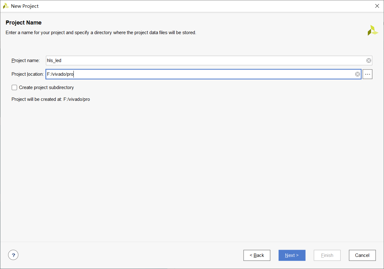
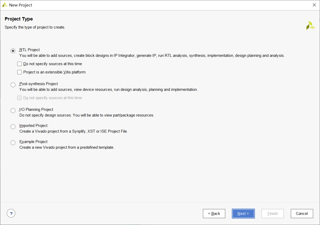
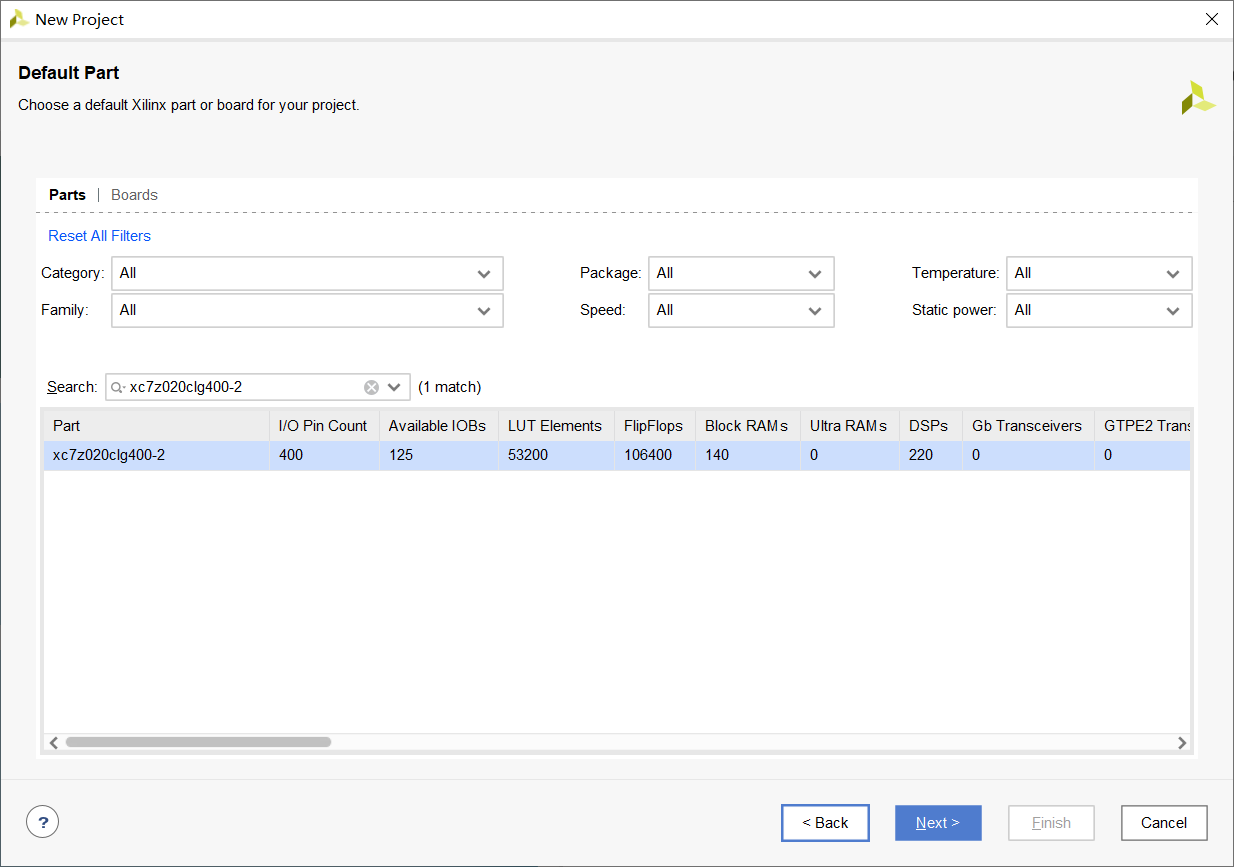
1. New project
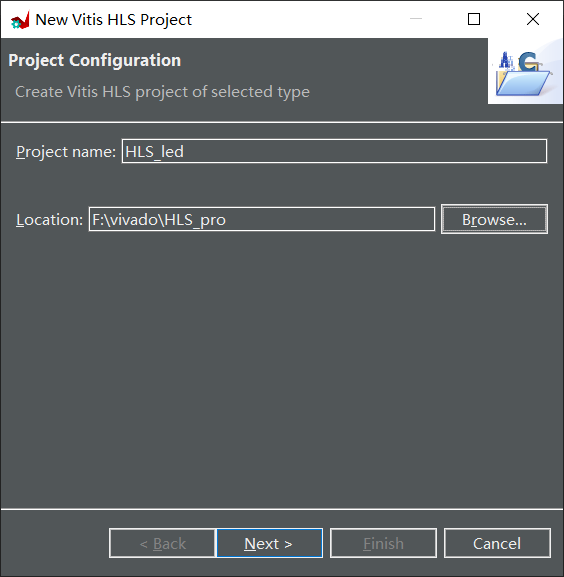
Select the fixed function, and here you can directly next
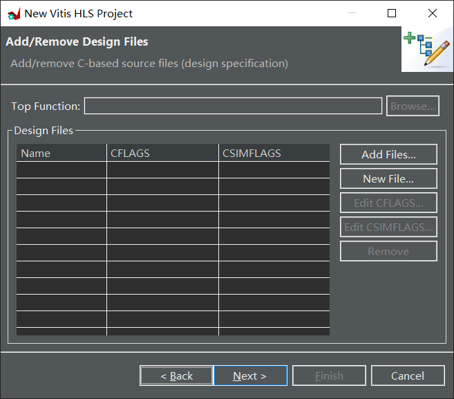
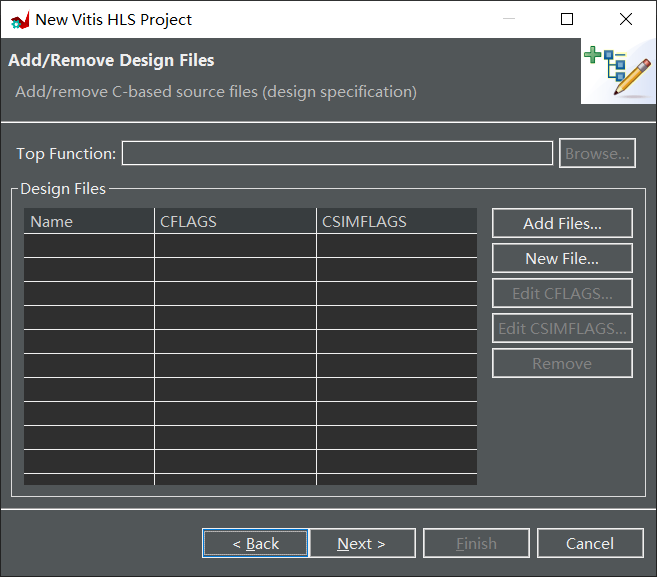
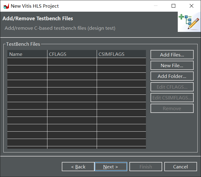
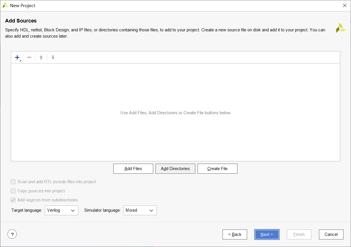
Add c simulation file, testbench file, next
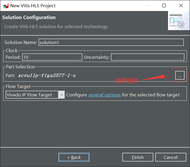
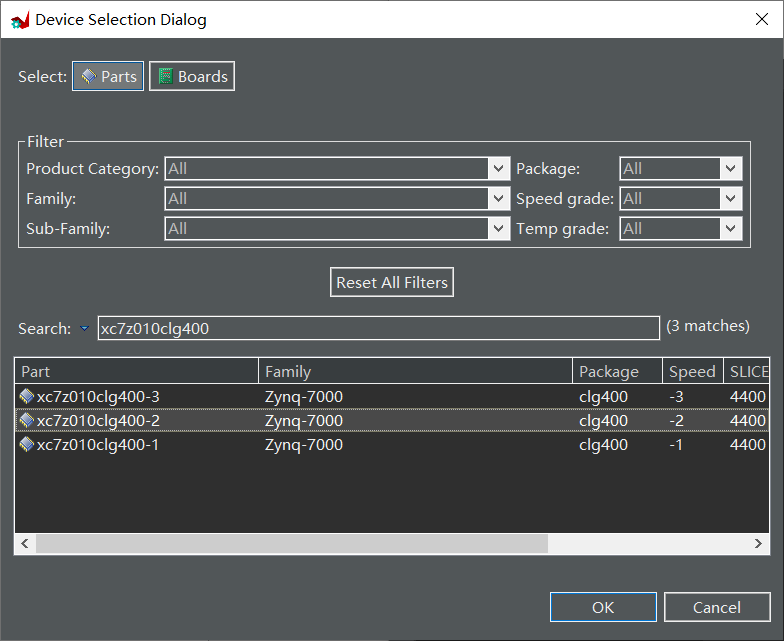
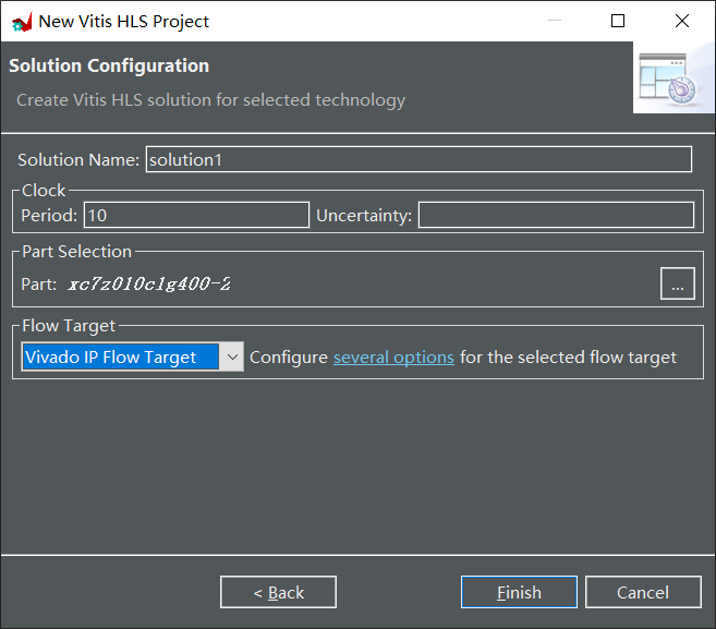
Select xc7z020clg400-2 here, corresponding to Z7-Lite7020
New project completion page
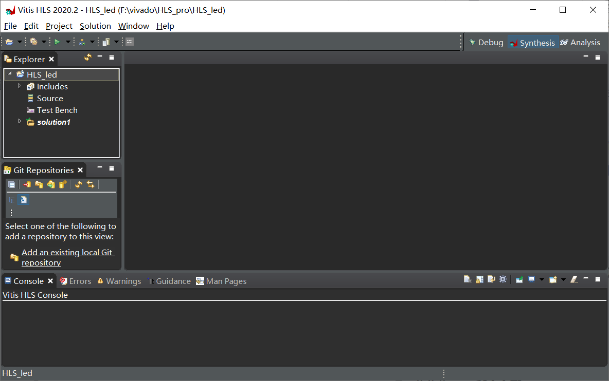
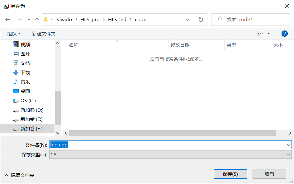
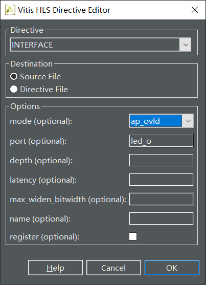
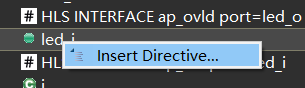
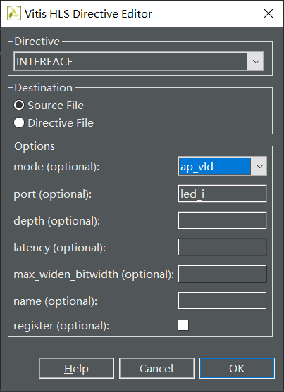
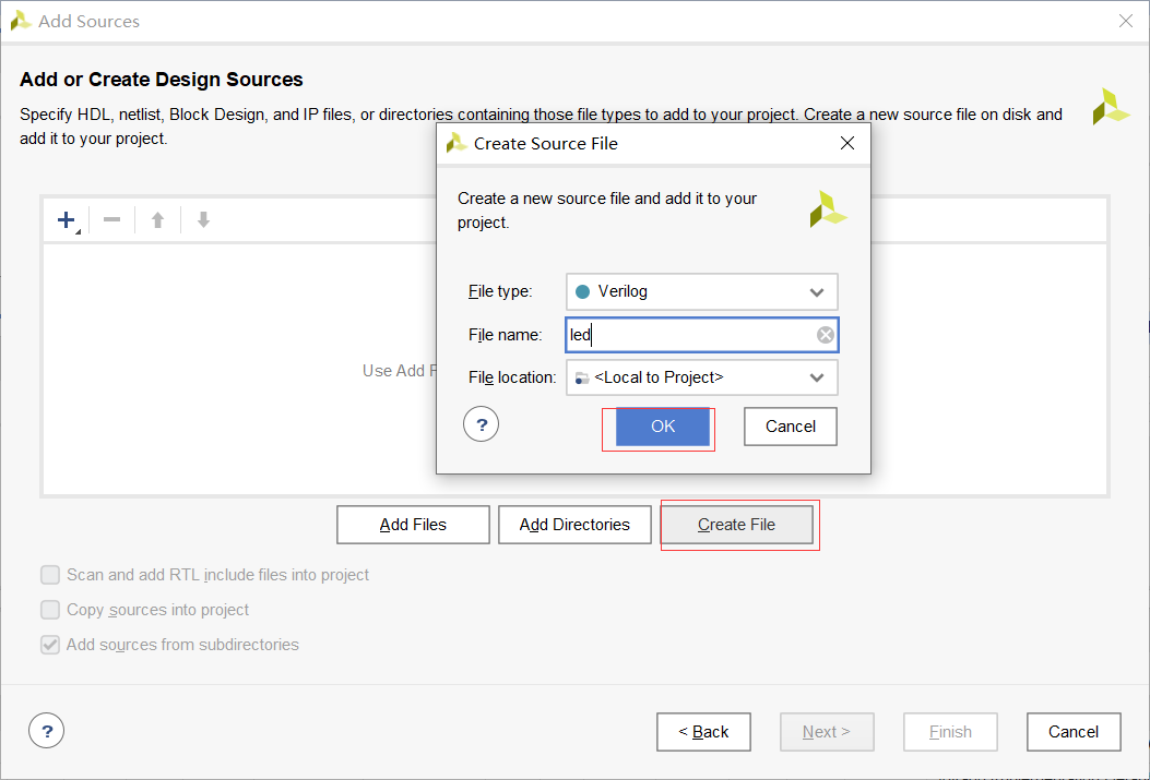
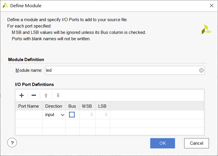
2. Add source file
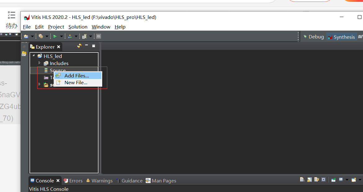
Add header files in the same way
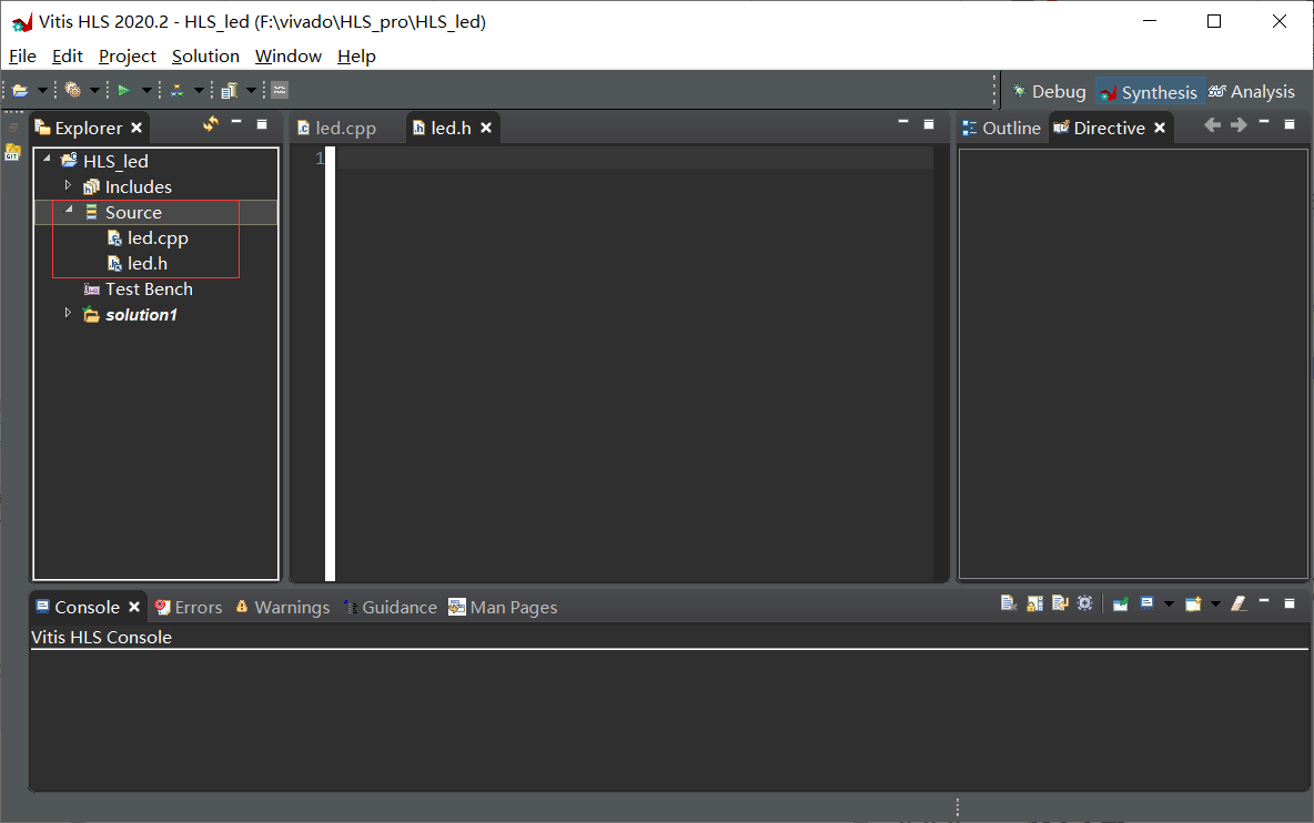
led.h code
 #ifndef _SHIFT_LED_H_
 #define _SHIFT_LED_H_
 #define CNT_MAX 100000000
 //#define CNT_MAX 100
 #define FLASH_FLAG CNT_MAX-2
 typedef int led_t;
 typedef int cnt_t;
 void flash_led(led_t *led_o , led_t led_i);
 #endif
Where the maximum count is CNT_MAX 100000000 is the number of counts required to count one second at 100M clock frequency
FLASH_FLAG is the sign that the LED flashes. When the value is counted
When, the LED changes
flash_led is a function that needs to be designed in this project
Subsequent optimization code
led.h
 #ifndef _SHIFT_LED_H_
 #define _SHIFT_LED_H_

 #include "ap_int.h"
 #define CNT_MAX 100000000
 //#define CNT_MAX 100
 #define FLASH_FLAG CNT_MAX-2
 //typedef int led_t;
 //typedef int cnt_t;
 typedef ap_int<1>led_t;
 typedef ap_int<32>cnt_t;
 void flash_led(led_t *led_o , led_t led_i);
 #endif
led.h code
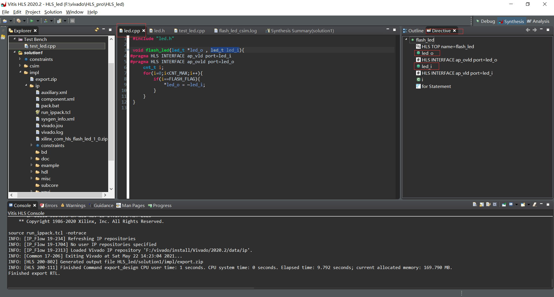
 #include "led.h"

 void flash_led(led_t *led_o , led_t led_i){
	 cnt_t i;
	 for(i=0;i<CNT_MAX;i++){
		 if(i==FLASH_FLAG){
			 *led_o = ~led_i;
		 }
	 }
 }
Variable i count to FLASH_FLAG led_o the state of the has changed
3. Add c simulation file
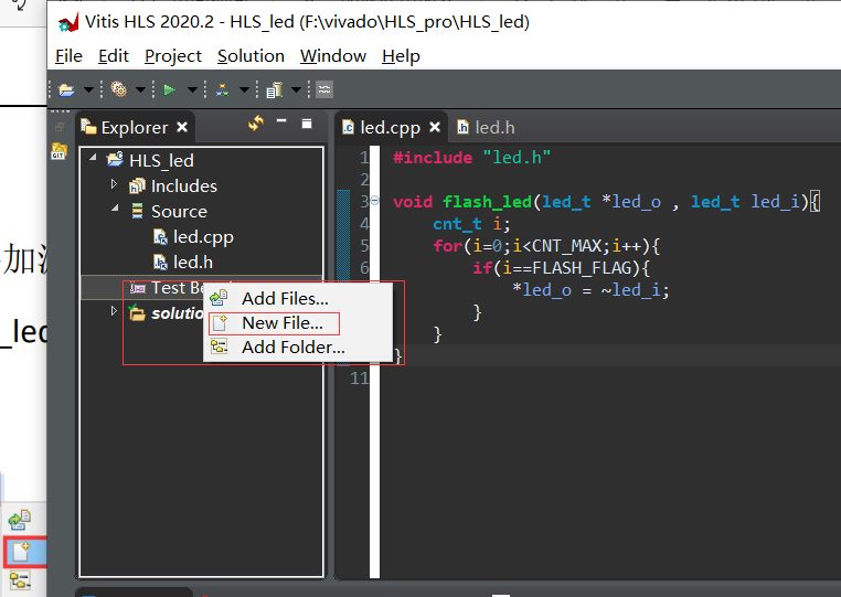
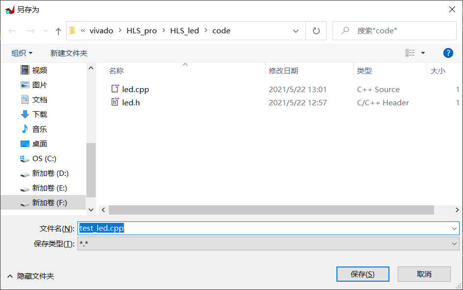
test_led.cpp code
#include "led.h"
#include <stdio.h>

 int main(){

	 led_t led_i=0x01;
	 led_t led_o;
	 const int SHIFT_TIME = 4;
	 int i;
	 for(i=0;i<SHIFT_TIME;i++){
		 flash_led(&led_o , led_i);
		 led_i = led_o;
		 printf("shift_out is %d \n",(int)(led_o&0x01));
	 }
 }
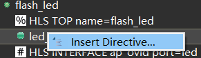
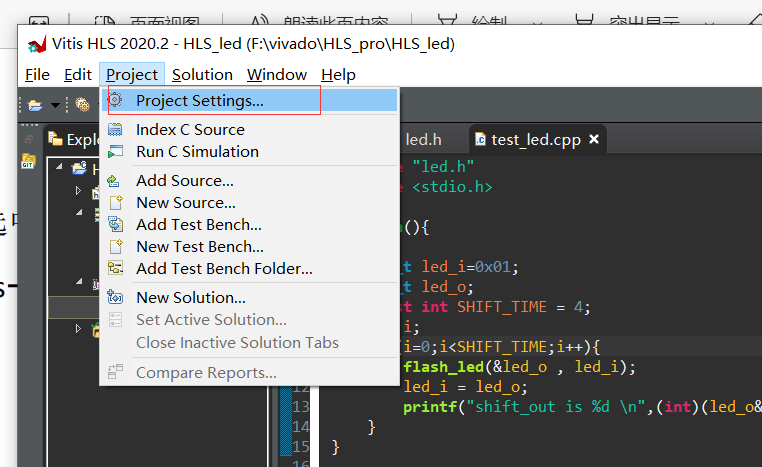
Subsequent optimization settings
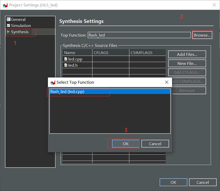
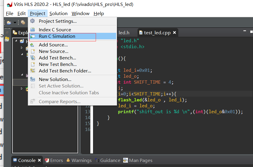
4. C simulation and C synthesis
Select flash_led as top-level function
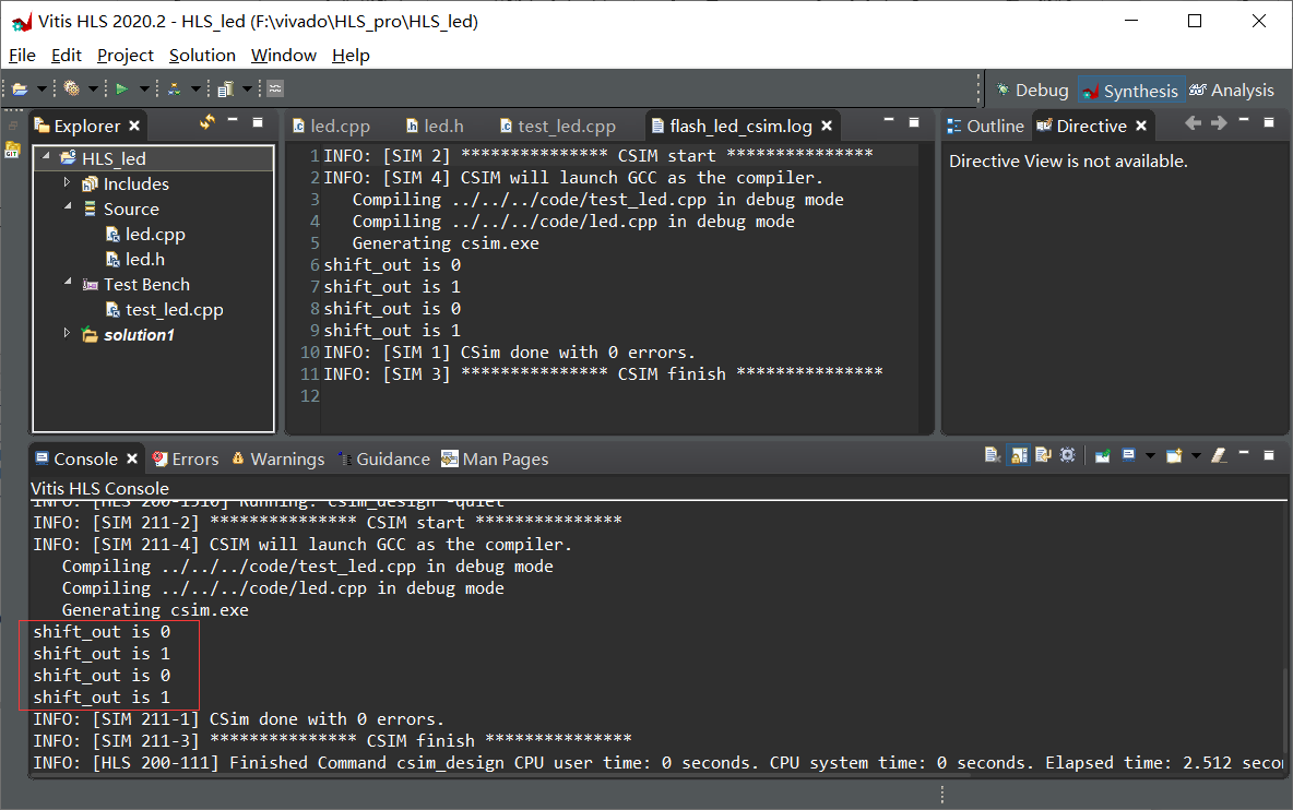
c simulation
c the simulation results are consistent with the expectation
c comprehensive
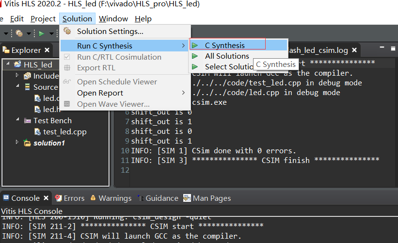
Result success
Latency refers to the time it takes to design a circuit to complete a task
Interval refers to the time interval between two tasks
Number of FF triggers: 62
Number of LUT lookup tables: 105
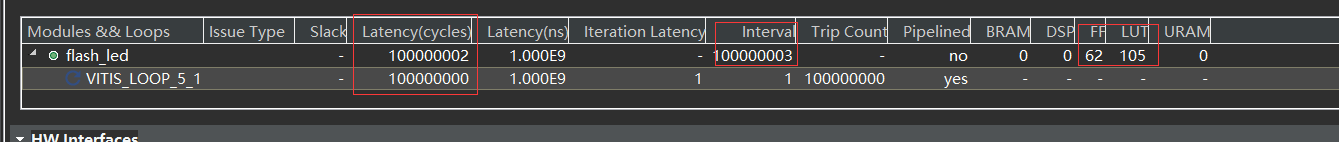
Other generated results are not concerned for the time being (because I really don't understand it, and this project doesn't need to be concerned)
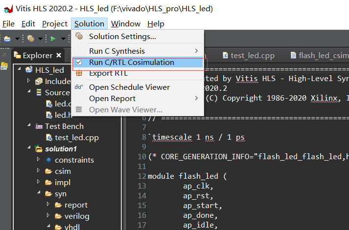
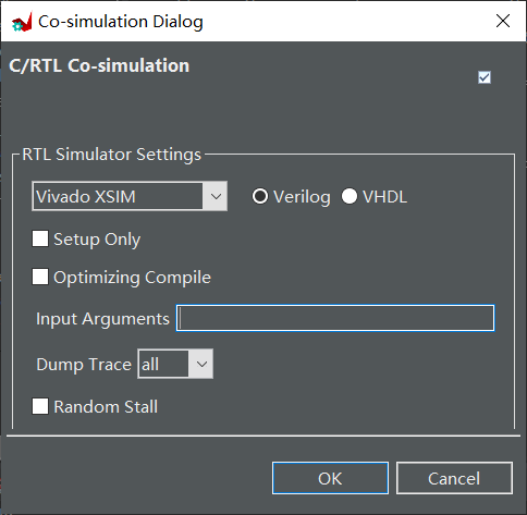
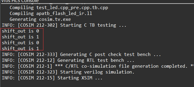
Joint simulation
The simulation results are consistent with c
(2) Burn
1. Export the IP core generated by HLS project
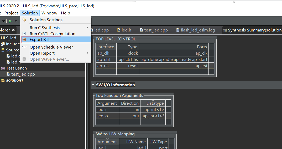
Don't change, just OK
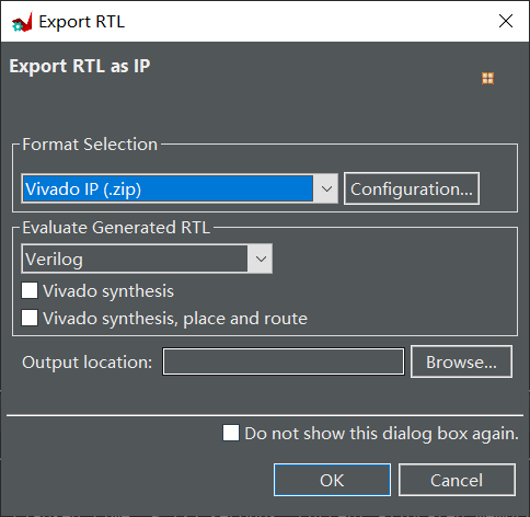
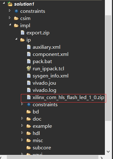
The exported IP core will be found in the Solution folder
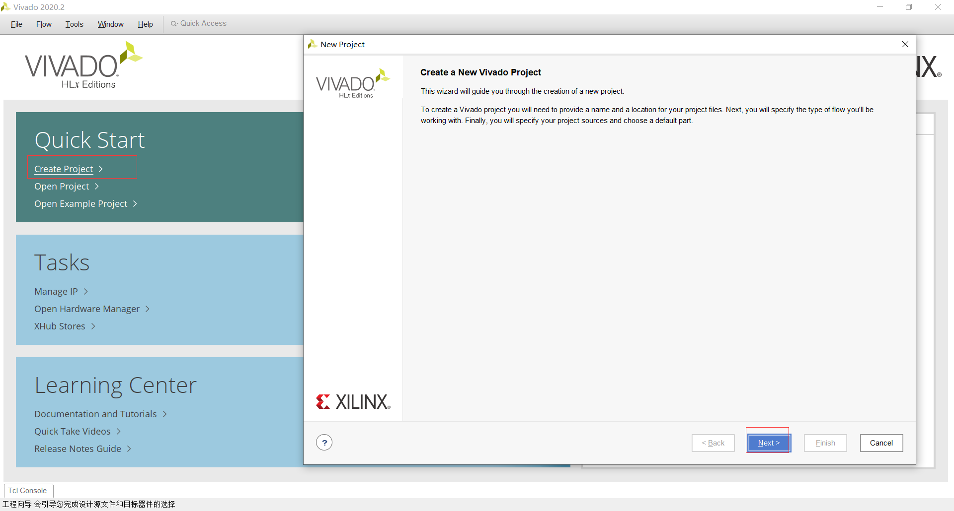
vivado project import ip
Open vivado to create a new project

Add ip
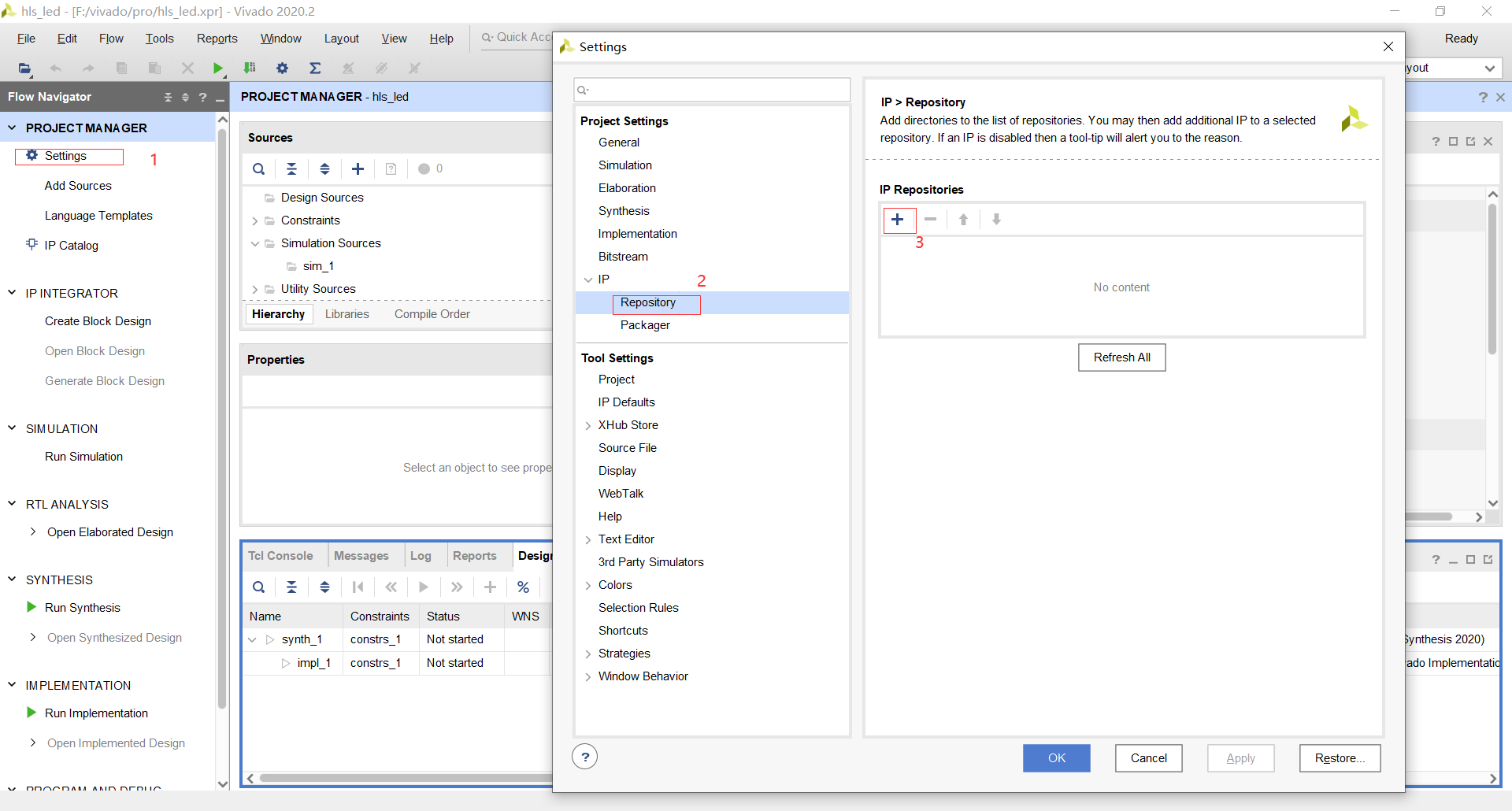
Navigate to solution
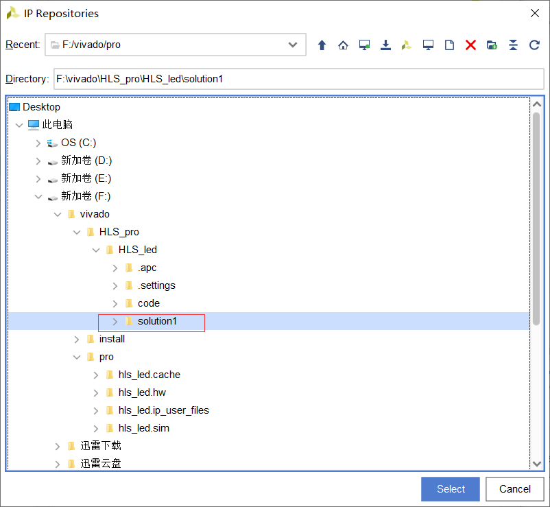
Apply after adding successfully
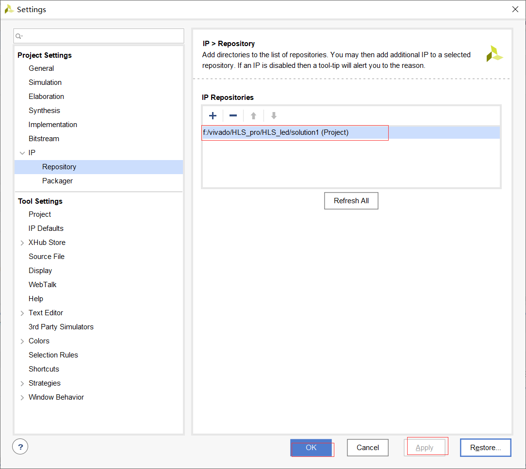
Added successfully
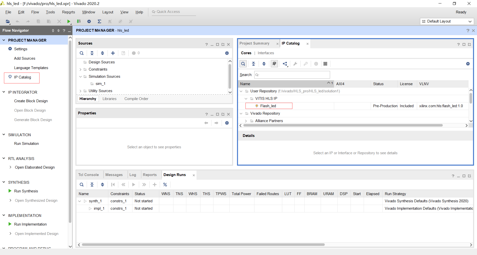
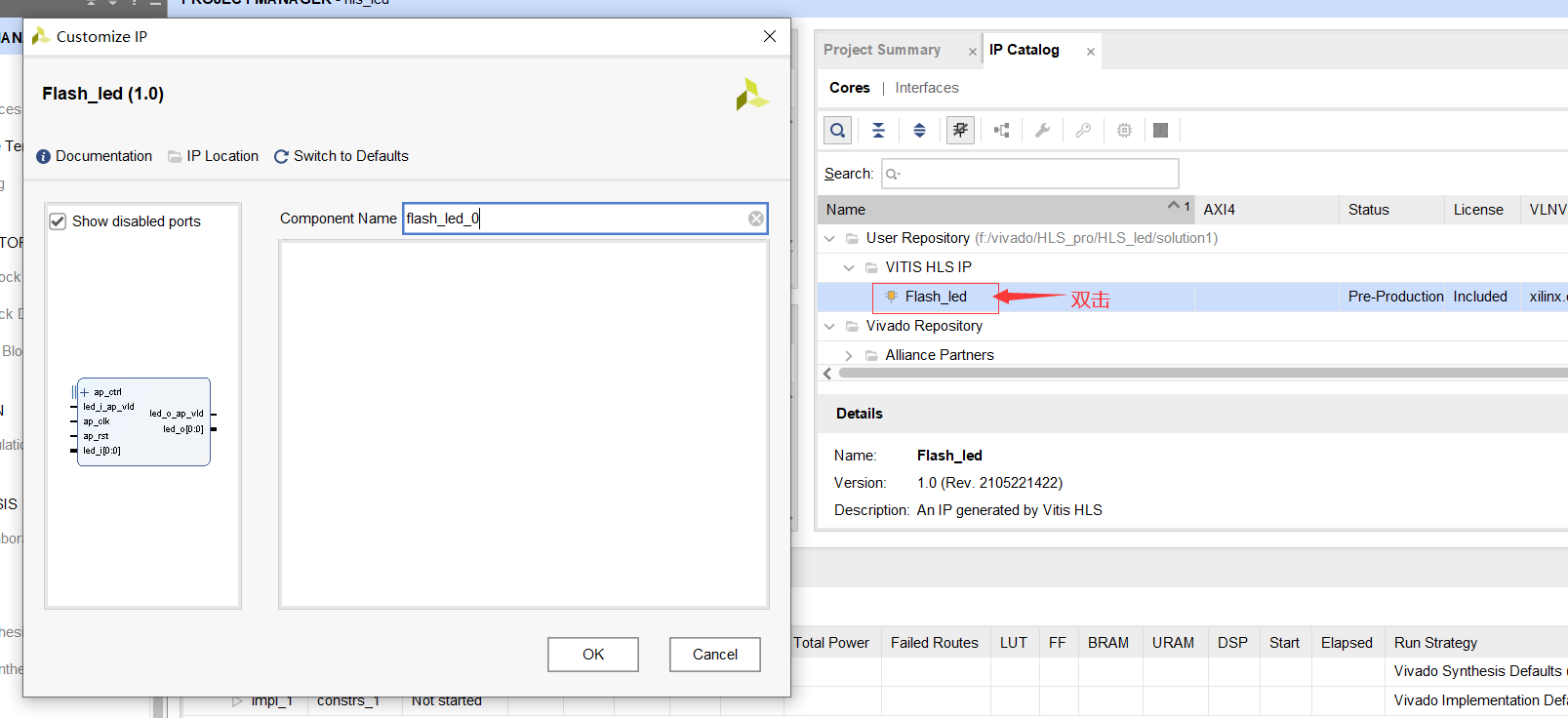
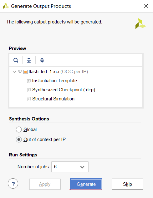
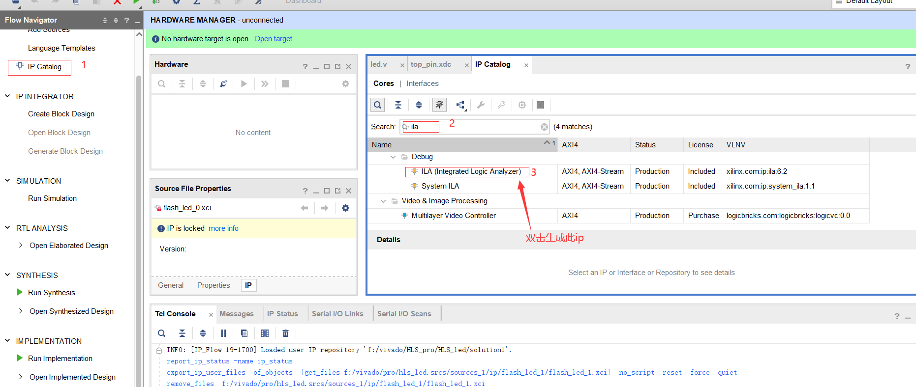
Select the IP generated by HLS in the IP Catalog, double-click and generate the IP
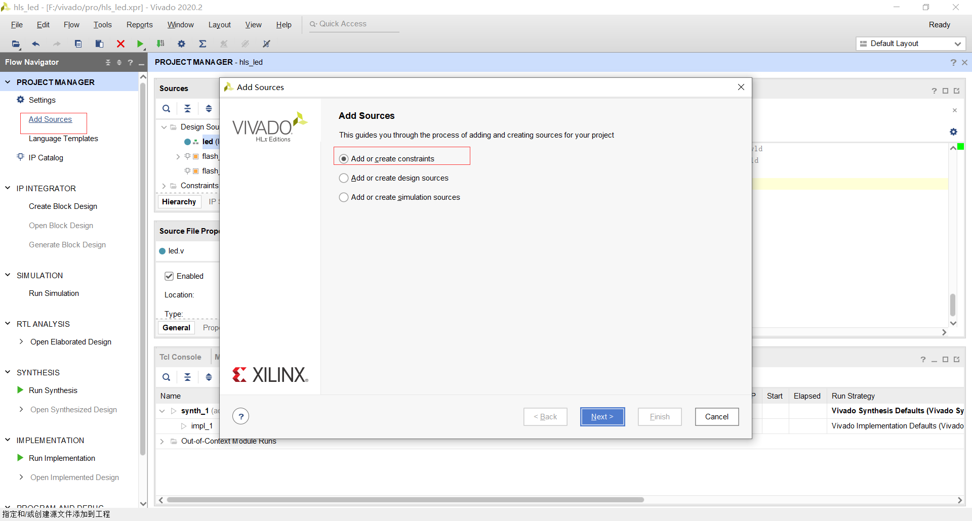
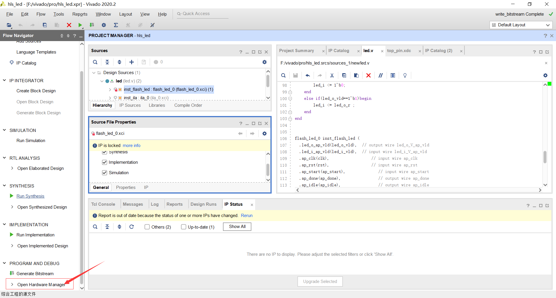
Add a new file to the project to complete this experiment
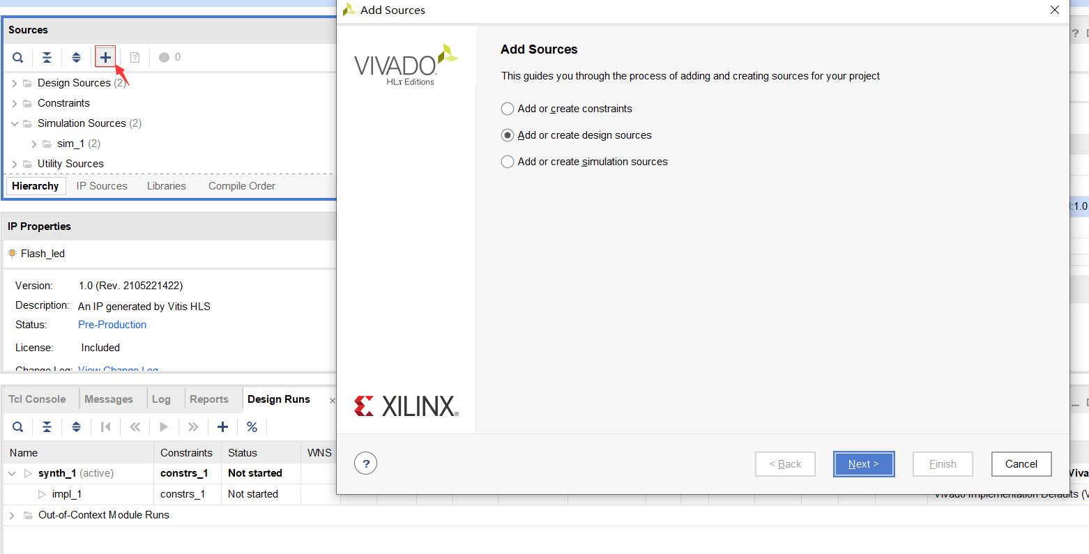
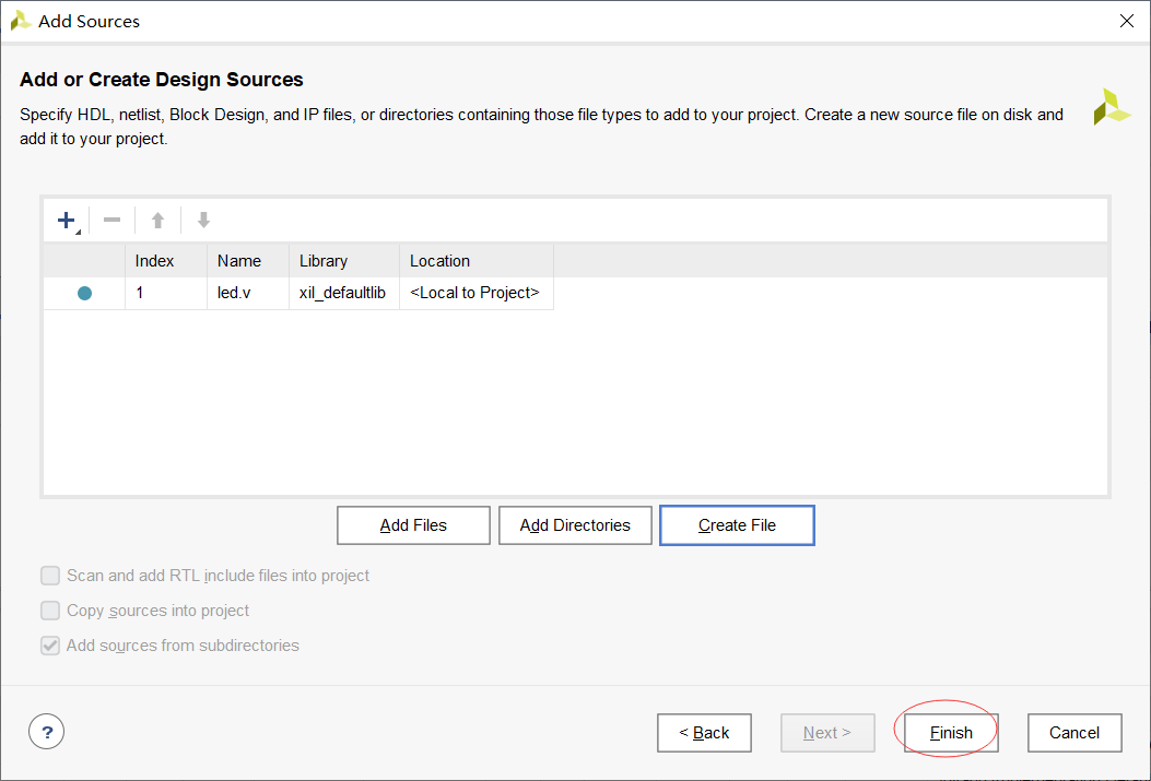
led.v is the code that instantiates the generated HLS IP into the project
    //
    // Company:
    // Engineer:
    //
    // Create Date: 2021/05/22 14:40:22
    // Design Name:
    // Module Name: led
    // Project Name:
    // Target Devices:
    // Tool Versions:
    // Description:
    //
    // Dependencies:
    //
    // Revision:
    // Revision 0.01 - File Created
    // Additional Comments:
    //
    //


     `timescale 1ns / 1ps
     module flash_led(
     input wire clk ,
     input wire rst_n ,
     output wire led_o
     );

     wire rst ;//Synchronous reset
     wire ap_ready ;//The next data can be received at present
     reg ap_start ;//IP start working
     reg led_i_vld ;//The input data is valid
     wire led_o_vld ;
     reg led_i ;//Input led signal
     wire led_o_r ;
     wire ap_done ;
     wire ap_idle ;
     reg [1:0] delay_cnt ;
     assign rst = ~rst_n ;
     assign led_o = led_o_r ;

     //----------------delay_cnt------------------
     always @(posedge clk) begin
     if (rst==1'b1) begin
     delay_cnt <= 'd0;
     end
     else if(delay_cnt[1]==1'b0) begin
     delay_cnt <= delay_cnt + 1'b1;
     end
     end

     //----------------ap_start------------------
     always @(posedge clk) begin
     if (rst==1'b1) begin
     ap_start <= 1'b0;
     end
     else if(delay_cnt[1]==1'b1)begin
     ap_start <= 1'b1;
     end
     end

     //----------------led_i_vld------------------
     always @(posedge clk) begin
     if (rst==1'b1) begin
     led_i_vld <= 1'b0;
     end
     else if(delay_cnt[1]==1'b1)begin
     led_i_vld <= 1'b1;
     end
     end

     //----------------ap_i------------------
     always @(posedge clk) begin
     if (rst==1'b1) begin
     led_i <= 1'b0;
     end
     else if(led_o_vld==1'b1)begin
     led_i <= led_o_r ;
     end
     end


     flash_led_0 inst_flash_led (
     .led_o_ap_vld(led_o_vld), // output wire led_o_V_ap_vld
     .led_i_ap_vld(led_i_vld), // input wire led_i_V_ap_vld
     .ap_clk(clk), // input wire ap_clk
     .ap_rst(rst), // input wire ap_rst
     .ap_start(ap_start), // input wire ap_start
     .ap_done(ap_done), // output wire ap_done
     .ap_idle(ap_idle), // output wire ap_idle
     .ap_ready(ap_ready), // output wire ap_ready
     .led_o_V(led_o_r), // output wire [0 : 0] led_o_V
     .led_i_V(led_i) // input wire [0 : 0] led_i_V
     );

     endmodule
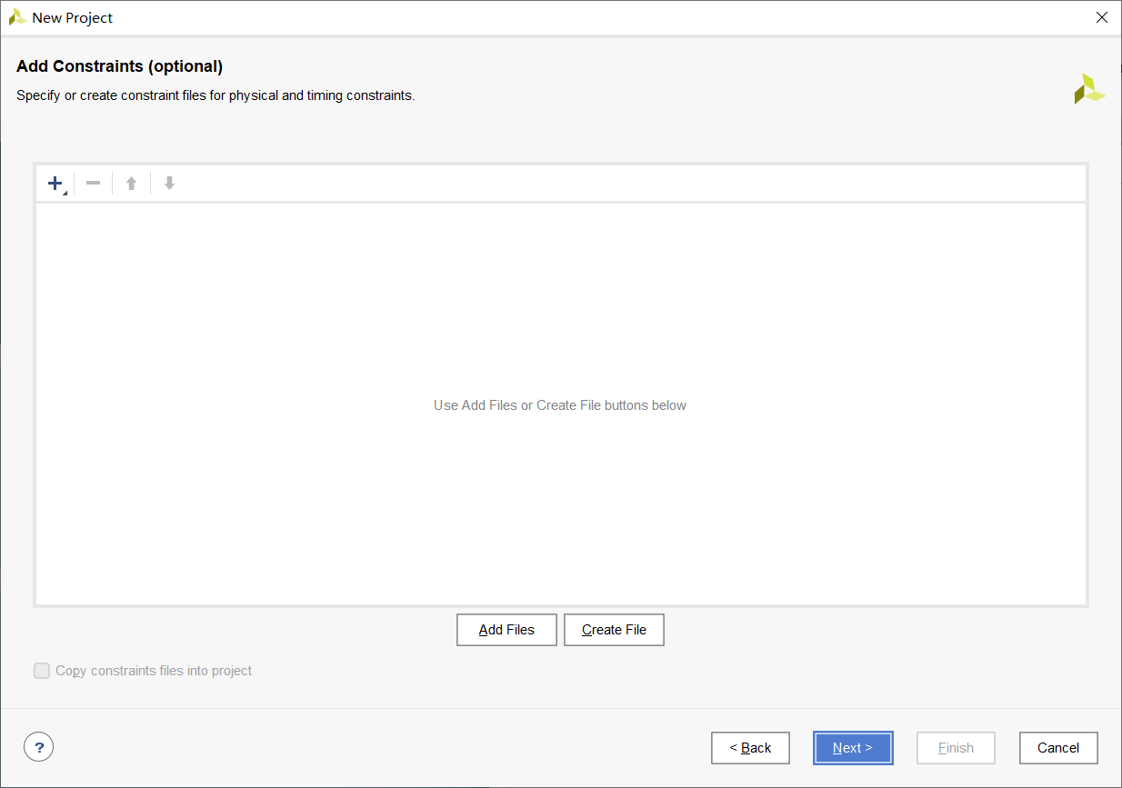
The next step is to add a constraint file
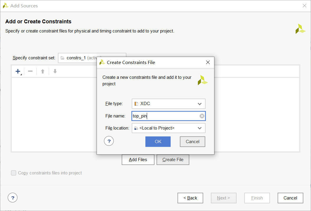
top_pin.xdc
##############LED define##################
set_property PACKAGE_PIN P15 [get_ports {led_o}]
set_property IOSTANDARD LVCMOS33 [get_ports {led_o}]
##############Reset define##################
set_property PACKAGE_PIN P16 [get_ports {rst_n}]
set_property IOSTANDARD LVCMOS33 [get_ports {rst_n}]
##############50M CLK define##################
create_clock -period 20.000 -name clk -waveform {0.000 10.000} [get_ports clk]
set_property PACKAGE_PIN N18 [get_ports {clk}]
set_property IOSTANDARD LVCMOS33 [get_ports {clk}]
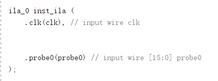
Add ila to observe the intermediate process
This ip corresponds to In v file
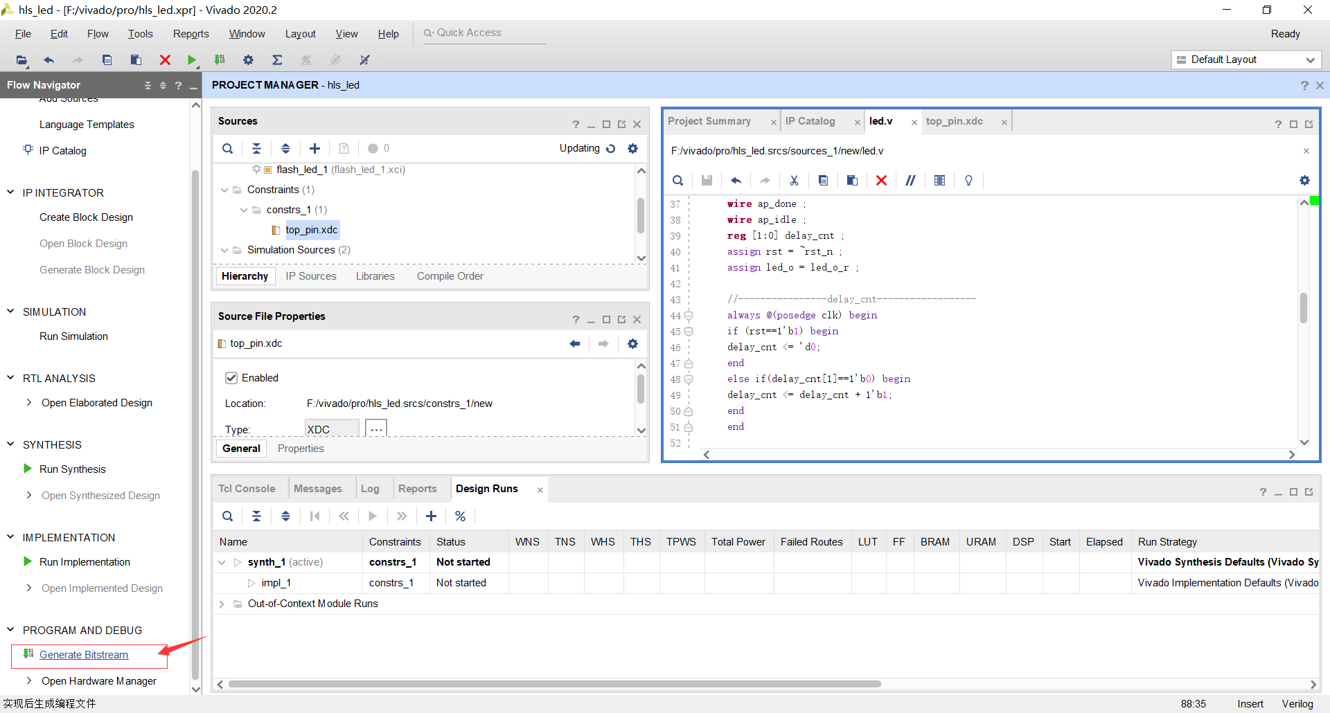
Generate bit stream file
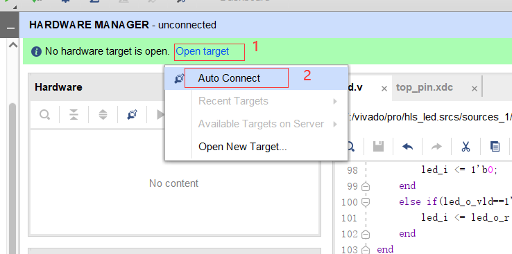
After completion, open the hardware burning page
Connect the board to the computer and click auto connect to automatically find the connected board
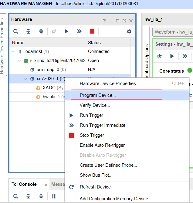
Right click Program Device
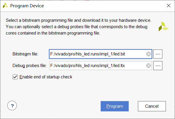
Here, the Program that can be burned will be filled in automatically. Click Program to burn

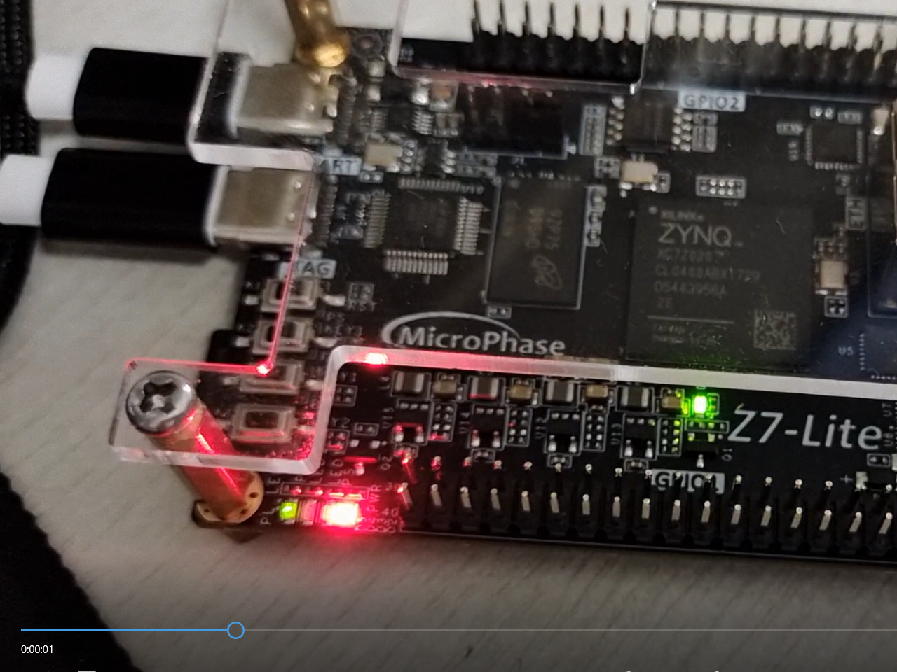
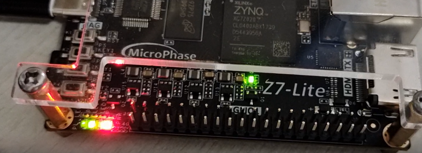
result
The video is too big to pass on
Summary: there are still a lot of operations that I don't understand, but I have a certain understanding of the routine of hls using xilinx after I generally finish it. I won't be completely blind before I did it. As for the principle part, I can only say that a few understand it, and most of them still do what they should do.
Learning source: microphase board tutorial, including video, pdf, etc