catalogue
1. Experiment contents and steps:
3. Explain the steps in detail
3.2 timer output PWM configuration
5. Program design (Standard Library)
6. Program design (HAL Library)
11. Universal timer PWM
1. Experiment contents and steps:
1. Through timer 2, an interrupt of 50Hz=20ms cycle is generated through frequency division and reload value, and after 50 interrupts (i.e. 1s), the LED is reversed.
2. The LED breathing lamp is realized through the PWM output of timer 2 channel 1 (PA0).
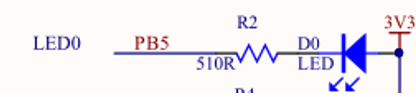
2. Hardware description
The hardware of this circuit is shown in the figure below. The LED lamp is connected with GPIOB5. The low level is on and the high level is off.
3. Explain the steps in detail
3.1 timer configuration
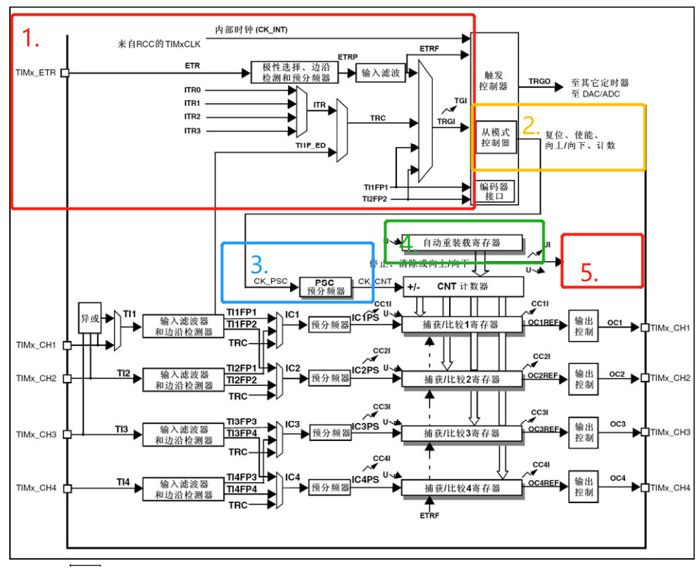
1. Select the internal clock source for clock selection;
2. Select counting mode, select counting up;
3. Timer frequency division selection, internal clock source = 2*APB1=72M, frequency division 720 to obtain timer clock 100KHz
4. Automatic reloading: the configuration is 2000, i.e. 100kHz / 2000 = 50Hz = 20ms (cycle);
5. Interrupt source configuration: configure only upper and lower overflow interrupts to enable interrupts.
1. Clock selection
Internal clock source:
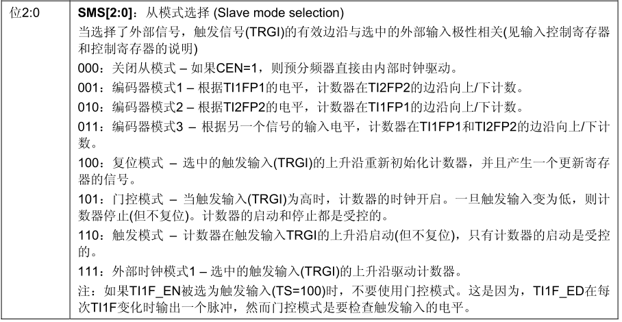
TIMx_ SMS[2:0]=000 in smcr register, turn off slave mode
The internal clock is used in this experiment:
TIMx_ SMCR &= ~((u32)0x07<<0); / / turn off slave mode
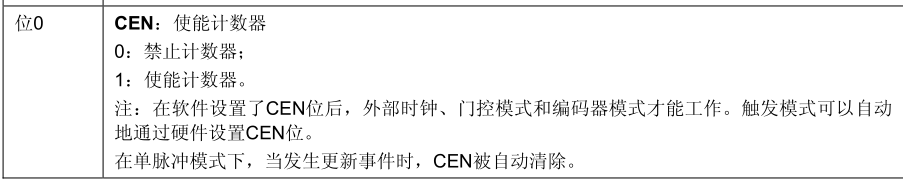
TIMx_ CEN (bit 0) of CR1 register determines the enable / disable of timer.
The CEN bit of the internal clock source (CK_INT) is written as' 1 '.
In this experiment:
TIMx_ CR1 |= ((u32)0x01<<0); / / enable counter
2. Counting direction selection
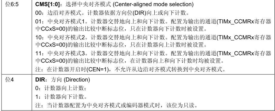
TIMx_ CMS[1:0]=00 for CR1, edge alignment mode. The counter counts up or down according to the direction bit (DIR).
TIMx_ The DIR bit of CR1 determines the counting direction of the timer.
Bit up counting mode is configured in this experiment:
TIMx_ CR1 &= ~((u32)0x03<<5); / / edge alignment mode
TIMx_ CR1 &= ~((u32)0x01<<4); / / count up mode
3. Timer clock division
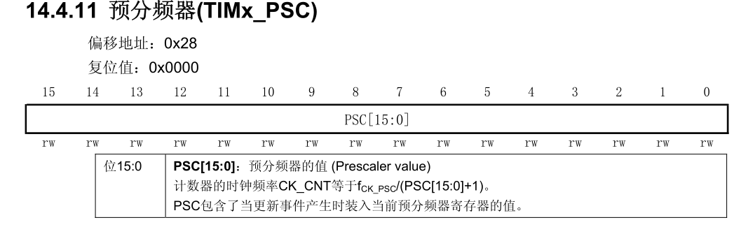
The timer clock is CK_CNT=F(CK_PSC)/(PSC[15:0]+1).
In this experiment:
Known clock source f (ck_psc) of timer 2 = 2 * apb1 (72MHz)
Frequency division value 720-1, timer clock CK_CNT=72M/(720-1+1)=100KHz
4. Auto reload at value
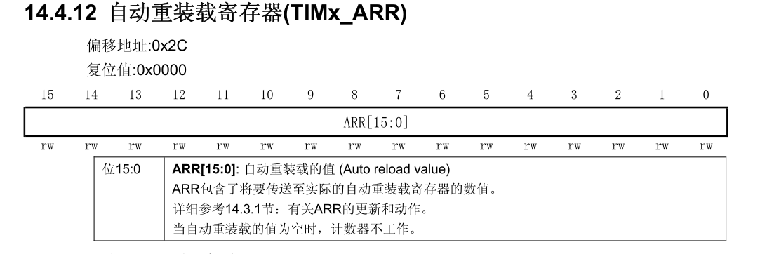
In this experiment:
If the automatic reload value is 2000, the timer interrupt cycle is: 100KHz/2000=50Hz=20ms.
5. Update interrupt enable
Configure only upper and lower overflow interrupts by timx_ Determined by USR (second bit) in CR1 register.
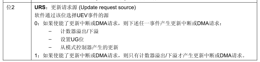
TIMx_ CR1 |= ((u32)0x01<<2); / / interrupt only when overflow occurs
Update interrupt enable in timx_ UIE (bit 0) in the Dier register.
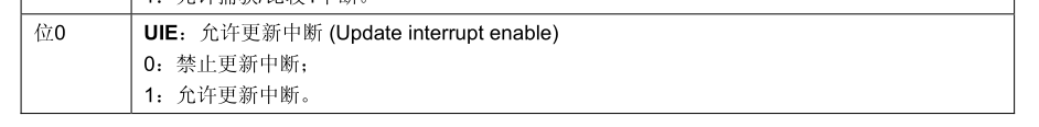
In this experiment:
TIMx_ DIER |= (u32)0x01<<0; / / enable interrupt
NVIC interrupt priority configuration and enabling;
SET_NVIC_IP(TIM2_IRQn,14); / / NVIC interrupt enable (this is a self written function)
At this time, configure timer 2 interrupt priority to 14 to enable NVIC TIM2 interrupt manager.
6. Interrupt function
In the interrupt function, by judging timx_ UIF (bit 0) in SR status register to determine whether it is an update interrupt.
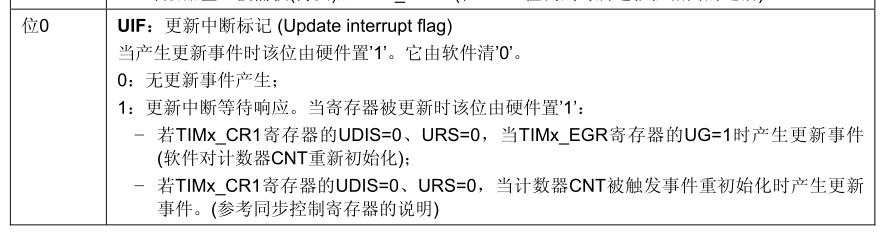
If it is 1, it means that the update is interrupted and needs to be cleared by software.
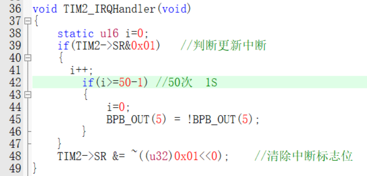
The interrupt function is as follows:
After 50 interruptions (i.e. 1S), the LED light reverses.
3.2 timer output PWM configuration
PWM configuration steps:
1. GPIO configuration of PWM;
2. TIM2 configuration;
3. PWM duty cycle setting;
4. Configure effective level polarity;
5. Configure PWM mode;
6. Configure the corresponding preload register buffer;
7. PWM output enable;
1. GPIO configuration for PWM
Comparison channel 1 (PA0) of TIM2 should be configured as push-pull multiplexed output.
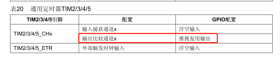
This function is written by itself:
GPIOX_PIN_SetMode(GPIOA,0,GPIOx_AF_PP|GPIOx_OUT_10M); / / PA0 multiplex push-pull output
2. TIM2 configuration
As shown in 3.1, the timer configuration is consistent.
The clock configured with TIM2 in this experiment is: 72M/720=100KHz (timer clock) 100k / 2000 = 50Hz = 20ms (cycle)
3.PWM duty cycle setting
PWM duty cycle is controlled by TIMx_CCRx register is configured. The description of the register is as follows:
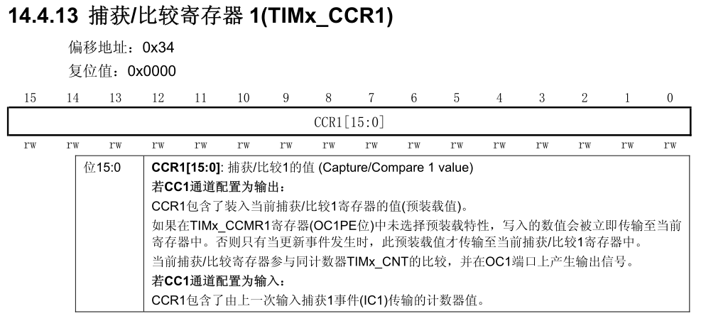
In this experiment, the initial duty cycle is 50%, that is:
TIMx_CCRx= 1000; / / duty cycle 50%
4. Configure effective level polarity
The polarity of OCx is the output level when the effective result is compared. The register description is as follows:
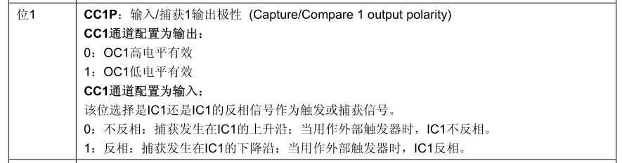
TIMx_ The CC1P bit (bit 1) in the CCER register determines whether the effective level is high or low.
In this experiment, it is configured as high-level effective:
TIMx_ CCER &= ~(0x01<<1); / / OC1 high level active
5. Configure PWM mode
In timx_ The OCxM bit in the ccmrx register is written to '110' (PWM mode 1) or '111' (PWM mode 2). TIMx_ OCxM bit in ccmrx register is as follows:
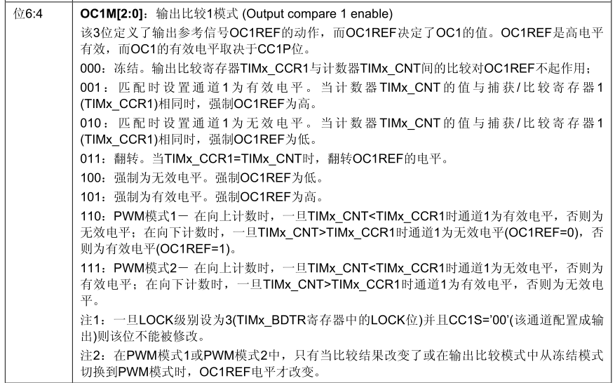
In timx_ The OCxM bit in the ccmrx register is written to '110' (PWM mode 1) or '111' (PWM mode 2)
Count up configuration:
PWM mode 1: when timx_ CNT<TIMx_ When ccrx, the PWM signal reference OCxREF is high;
Down count configuration:
When timx_ CNT>TIMx_ When ccrx, the reference signal OCxREF is low;
PWM mode is used in this experiment. PWM mode 1 is used:
TIMx_ CCMRx &= ~(0x07<<4); / / clear the output comparison 1 mode
TIMx_ CCMRx |= 0x06<<4; / / mode 1
6. Configure the corresponding preload register
This step is to configure whether buffering is required after writing the comparison register. If there is a buffer, the update event is updated to the corresponding register only when it comes; If not, it will be directly updated to the corresponding register. There is no big problem.
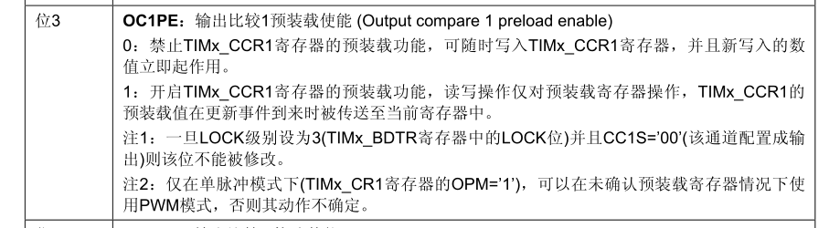
Enable preload in this experiment:
TIMx_ CCMR1 |= 0x01<<3; / / output comparison 1 preload enable
7. Output enable
TIMx_ The CCxE bit in the CCER register controls the OCx output enable. OCx bit is shown in the figure below:
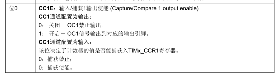
Enable output required to use PWM:
TIMx_ CCER |= (0x01<<0); / / enable output
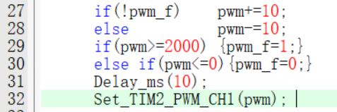
8. Realization of breathing lamp
The PWM value is increased by 10 or decreased by 10 without 10ms to achieve the effect of breathing lamp.
4. Program design (register)
Timer interrupt see the source code, here through TIM2-PWM LED into a breathing lamp
Configuration steps:
1. GPIO clock enable, TIM clock enable;
2. GPIO configured with PWM output: push-pull output;
3. Configure the frequency division, preload value, up and down counting mode of timer TIM2, and enable the timer;
4. Interrupt manager NVIC enable, priority configuration (if interrupt is required);
5. Configure PWM duty cycle, mode, effective polarity and comparison enable;
6. Write PWM modification function.
Source code: only the TIM2-PWM configuration part is listed here
//Initialization timer 2
//APB1 = 72MHz
void TIM2_Config(u16 psc,u16 arr)
{
    //Clock
    RCC->APB1ENR    |=  RCC_APB1ENR_TIM2EN;

    //Clock selection (internal clock source)
	TIM2->SMCR &= ~((u32)0x07<<0);	    //Turn off slave mode
    //Counting direction selection
    TIM2->CR1 &= ~((u32)0x03<<5);	    // Edge alignment mode
	TIM2->CR1 &= ~((u32)0x01<<4);		//Count up mode
    //prescale
    TIM2->PSC = psc;                    //frequency division
    //Reload value
    TIM2->ARR = arr;                    //Reload at value
    //Clear counter
    TIM2->CNT = 0;                      //Clear current counter
    //Enable interrupt
    TIM2->CR1 |= ((u32)0x01<<2);	    //Only overflow is interrupted
    TIM2->DIER |= (u32)0x01<<0;         //Allow update interrupt
    SET_NVIC_IP(TIM2_IRQn,14);          //NVIC interrupt enable
    //Enable timer
    TIM2->CR1 |= ((u32)0x01<<0);	    //Enable counter

}

/*
    TIM2_PWM_to configure
*/
void TIM2_PWM_Config(void)
{
    //GPIO initialization
    GPIOX_PIN_SetMode(GPIOA,0,GPIOx_AF_PP|GPIOx_OUT_10M);   //PA0 multiplex push-pull output
    //TIM2 initialization
    TIM2_Config(720-1,2000-1);  // 72m / 720 = 100kHz 100k / 2000 = 50Hz = 20ms (cycle)
    //Comparison register
    TIM2->CCR1 = 1000;          //Duty cycle 50%
    //Output comparison mode (mode 1)
    TIM2->CCMR1 &= ~(0x07<<4);  //Clear output comparison 1 mode
    TIM2->CCMR1 |= 0x06<<4;     //Mode 1
    //Output comparison 1 preload enable
    TIM2->CCMR1 |= 0x01<<3;     //Output comparison 1 preload enable
    //Compare 1 output polarity
    TIM2->CCER &= ~(0x01<<1);   //OC1 high level active
    //Enable compare 1 output
    TIM2->CCER |= (0x01<<0);   //open

}

/*
    Set PWM for compare output 1
*/
void Set_TIM2_PWM_CH1(u16 pwm)
{
    TIM2->CCR1  =   pwm;
}


void TIM2_IRQHandler(void)
{
    static u16 i=0;
    if(TIM2->SR&0x01)   //Judge update interrupt
    {
      i++;
        if(i>=50-1) //50 times 1S
        {
            i=0;
            //BPB_OUT(5) = !BPB_OUT(5);
            printf("1S time\r\n");
        }
    }
    TIM2->SR &= ~((u32)0x01<<0);    //Clear interrupt flag bit
}
5. Program design (Standard Library)
Configuration steps:
1. GPIO clock enable, TIM clock enable;
2. Configure the GPIO of PWM output as push-pull output. Via GPIO_InitTypeDef structure configuration;
3. Configure the frequency division, preload value and up-down counting mode of timer TIM2. Through TIM_TimeBaseInitTypeDef structure configuration;
4. Interrupt manager NVIC enable, priority configuration (if interrupt is required). Via NVIC_ Configure inittypedef structure;
5. Configure PWM duty cycle, mode, effective polarity and comparison enable. Through TIM_OCInitTypeDef structure configuration;
6. Timer enable function, using: TIM_Cmd function enable;
7. PWM modification function: TIM_SetCompare1 function.
Source code: only the TIM2-PWM configuration part is listed here
#define TIM_x               TIM2
#define TIM_NVIC_IRQ       TIM2_IRQn
#define TIM_NVIC_PP        13
#define TIM_NVIC_SP        0

#define PWM_GPIOX           GPIOA
#define PWM_GPIOX_PIN       GPIO_Pin_0
#define PWM_GPIOX_MODE      GPIO_Mode_AF_PP / / multiplex push-pull
//Initialization timer 2
//APB1 = 72MHz
void TIM2_Config(u16 psc,u16 arr)
{
    TIM_TimeBaseInitTypeDef TIM_TimeBaseInitStruct;
    NVIC_InitTypeDef  NVIC_InitStruct;
    //Clock
    RCC_APB1PeriphClockCmd(RCC_APB1ENR_TIM2EN,ENABLE);    //TIM2 timer
    //Timer basic configuration
    TIM_TimeBaseInitStruct.TIM_Prescaler    =   psc;      //frequency division
    TIM_TimeBaseInitStruct.TIM_CounterMode  =   TIM_CounterMode_Up; //Count up
    TIM_TimeBaseInitStruct.TIM_Period    =   arr;       //From installed in value
    TIM_TimeBaseInit(TIM_x,&TIM_TimeBaseInitStruct);
    //Interrupt configuration
    TIM_ITConfig(TIM_x,TIM_IT_Update,ENABLE);
    //Priority configuration
    NVIC_InitStruct.NVIC_IRQChannel     =   TIM_NVIC_IRQ;
    NVIC_InitStruct.NVIC_IRQChannelCmd  =   ENABLE;
    NVIC_InitStruct.NVIC_IRQChannelPreemptionPriority   =   TIM_NVIC_PP;
    NVIC_InitStruct.NVIC_IRQChannelSubPriority  =   TIM_NVIC_SP;
    NVIC_Init(&NVIC_InitStruct);    //Set interrupt priority
    //Timer enable
    TIM_Cmd(TIM_x,ENABLE);
}

/*
    TIM2_PWM_to configure
*/
void TIM2_PWM_Config(void)
{
    GPIO_InitTypeDef  GPIO_InitStruct;
    TIM_OCInitTypeDef  TIM_OCInitStruct;
    //GPIO initialization
    GPIO_InitStruct.GPIO_Mode   =   PWM_GPIOX_MODE;
    GPIO_InitStruct.GPIO_Pin    =   PWM_GPIOX_PIN;
    GPIO_InitStruct.GPIO_Speed  =   GPIO_Speed_10MHz;
    GPIO_Init(PWM_GPIOX, &GPIO_InitStruct);     //Multiplexed push-pull output
    //TIM2 initialization
    TIM2_Config(720-1,2000-1);  // 72m / 720 = 100kHz 100k / 2000 = 50Hz = 20ms (cycle)
    //Channel configuration
    TIM_OCInitStruct.TIM_OCMode =   TIM_OCMode_PWM1;    //PWM1 mode
    TIM_OCInitStruct.TIM_OutputState    =   TIM_OutputState_Enable; //Compare enable
    TIM_OCInitStruct.TIM_OCPolarity     =   TIM_OCPolarity_High;    //Active level high level
    TIM_OCInitStruct.TIM_Pulse      =   1000;           //Duty cycle 50%
    TIM_OC1Init(TIM_x, &TIM_OCInitStruct);

}


//Interrupt function
void TIM2_IRQHandler(void)
{
    static u16 i=0;
    if(TIM_GetITStatus(TIM_x,TIM_IT_Update))   //Judge update interrupt
    {
      i++;
        if(i>=50-1) //50 times 1S
        {
            i=0;
            //BPB_OUT(5) = !BPB_OUT(5);
            printf("1S time\r\n");
        }
    }
    TIM_ClearITPendingBit(TIM_x,TIM_IT_Update);    //Clear interrupt flag bit
}
6. Program design (HAL Library)
The main difference between HAL library and standard library is that HAL library is highly encapsulated and relatively easy to use. Many judgment flag bits and clearing flag bits are completed by HAL library.
Summarize the operation of HAL Library: initialization + enable.
Configuration steps:
1. GPIO clock enable, TIM clock enable;
2. Through HAL_TIM_Base_Init function initializes timer operation;
3. Through HAL_TIM_Base_Start_IT function enables timer and interrupt;
4. Through HAL_NVIC_SetPriority,HAL_NVIC_EnableIRQ enables NVIC interrupt management and priority;
5. Through HAL_TIM_OC_ConfigChannel initializes PWM configuration;
6. Through HAL_TIM_OC_Start enable PWM;
7. Available in Hal_ TIM_ Base_ Initialize GPIO in mspinit callback function;
8. Call HAL_ in interrupt TIM_ Irqhandler interrupt processing function (it has the function of flag bit judgment and clearing, which can reduce the difficulty of development);
9. Write the update interrupt content in the update callback function (HAL_TIM_PeriodElapsedCallback);
Source code: only the TIM2-PWM configuration part is listed here
#include "My_GP_TIM.h"
#include "stdio.h"
#include "My_exti.h"
#include "My_bit.h"
#include "My_gpio.h"
//TIM2
TIM_HandleTypeDef TIM2_HandleStruct;

#define TIM_x              TIM2
#define TIM_NVIC_IRQ       TIM2_IRQn
#define TIM_NVIC_PP        13
#define TIM_NVIC_SP        0

#define PWM_GPIOX           GPIOA
#define PWM_GPIOX_PIN       GPIO_PIN_0
#define PWM_GPIOX_MODE      GPIO_MODE_AF_PP / / multiplex push-pull
//Initialization timer 2
//APB1 = 72MHz
void TIM2_Config(u16 psc,u16 arr)
{
    //Clock
    __HAL_RCC_TIM2_CLK_ENABLE();    //TIM2 timer
    //Timer basic configuration
    TIM2_HandleStruct.Instance   =   TIM_x;
    TIM2_HandleStruct.Init.Prescaler =   psc;    //frequency division
    TIM2_HandleStruct.Init.CounterMode   =   TIM_COUNTERMODE_UP; //Count up
    TIM2_HandleStruct.Init.Period    =   arr;    //From installed in value
    TIM2_HandleStruct.Channel    =   HAL_TIM_ACTIVE_CHANNEL_1;   //Channel 1
    HAL_TIM_Base_Init(&TIM2_HandleStruct);
    //Interrupt configuration
    HAL_TIM_Base_Start_IT(&TIM2_HandleStruct);
    //Priority configuration
    HAL_NVIC_SetPriority(TIM_NVIC_IRQ,13,0);    //Response priority is 13 min
    HAL_NVIC_EnableIRQ(TIM_NVIC_IRQ);           //Enable medium break

}

/*
    TIM2_PWM_to configure
*/
void TIM2_PWM_Config(void)
{
    GPIO_InitTypeDef GPIO_Init;
    TIM_OC_InitTypeDef TIM_OC_InitStruct;
    //Clock
    __HAL_RCC_GPIOB_CLK_ENABLE();
    //GPIO initialization
    GPIO_Init.Mode  =   PWM_GPIOX_MODE;
    GPIO_Init.Pin   =   PWM_GPIOX_PIN;
    GPIO_Init.Speed =   GPIO_SPEED_FREQ_MEDIUM;
    HAL_GPIO_Init(PWM_GPIOX,&GPIO_Init);   //Multiplexed push-pull output
    //TIM2 initialization
    TIM2_Config(720-1,2000-1);  // 72m / 720 = 100kHz 100k / 2000 = 50Hz = 20ms (cycle)
    //Channel configuration
    TIM_OC_InitStruct.OCMode    =   TIM_OCMODE_PWM1;        //PWM1 mode
    TIM_OC_InitStruct.OCPolarity    =   TIM_OCPOLARITY_HIGH;    //Active level high level
    TIM_OC_InitStruct.OCIdleState   =   TIM_OCIDLESTATE_SET;    //Compare enable
    TIM_OC_InitStruct.Pulse =   1000;   //Duty cycle 50%
    HAL_TIM_OC_ConfigChannel(&TIM2_HandleStruct,&TIM_OC_InitStruct,TIM_CHANNEL_1);
    HAL_TIM_OC_Start(&TIM2_HandleStruct,TIM_CHANNEL_1);
}


//Interrupt function
void TIM2_IRQHandler(void)
{
    HAL_TIM_IRQHandler(&TIM2_HandleStruct);
}

//Update event callback function
void HAL_TIM_PeriodElapsedCallback(TIM_HandleTypeDef *htim)
{
    static u16 i=0;
    i++;
    if(i>=50-1) //50 times 1S
    {
        i=0;
        //BPB_OUT(5) = !BPB_OUT(5);
        printf("1S time\r\n");
    }
}
7. Experimental results
1. Every 1S, the timer interrupt will output "1S timing";
2. PWM breathing lamp experiment, LED lamp will show breathing effect;