normal map
- The core modification is the normal value in the clip shader
uniform sampler2D normalMap;

void main()
{
    // Get normals from normal map range [0,1]
    normal = texture(normalMap, fs_in.TexCoords).rgb;
    // Convert normal vector to range [- 1,1]
    normal = normalize(normal * 2.0 - 1.0);

    [...]
    // Handle the light as usual
}
tangent space
-
Deal with the problem that the two coordinate systems are different
However, there is a problem that limits the use of the normal map just mentioned. All normal vectors in the normal map we used point in the positive z direction. The above example works because the surface normal of that plane also points in the positive z direction. However, what happens if we use the same normal map on a plane where the surface normal points in the positive Y direction? It's totally wrong to just look after it! This happens when the surface normal of the plane now points to y, while the sampled normal still points to z. The result is that the illumination still considers the surface normal to be the same as when it was facing the positive z direction; So the light is wrong. The following picture shows the approximation of the normals sampled on this surface: -
You can see that all normals are pointing in the z direction, and they should be pointing in the y direction towards the surface normal. One possible solution is to make a separate normal map for each surface. If it is a cube, we need 6 normal maps, but if there are countless surfaces facing different directions on the model, this is not feasible In fact, for complex models, you can store normals in all directions on the same map. You may have seen more than a blue normal map, but with such a normal map, you must remember the starting orientation of the model. If the model is moving, it is very inconvenient to record the transformation of the model; in addition, as the author said, If you apply a diffuse texture to different surfaces of the same object, like a cube, you need to do six normal maps, which is not desirable).
Another slightly difficult solution is to light in a different coordinate space. In this coordinate space, the normal map vector always points to the positive z direction of the coordinate space; all lighting vectors are transformed relative to the positive z direction. In this way, we can always use the same normal map, regardless of the orientation. This coordinate space is called tangent tangent space.
-
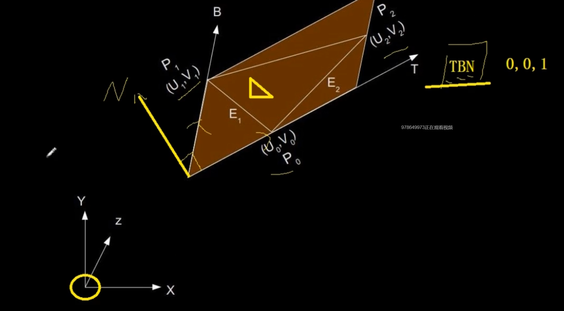
Multiply any vector by a TBN matrix (new base) and convert it to the value in model space. Everyone can just be in a coordinate system. (the three letters of TBN matrix represent tangent, bitangent and normal vectors respectively)
-
The derivation process is in the official document. The tangent and sub tangent are calculated from the vertex and texture coordinates of a triangle (because the texture coordinates and tangent vector are in the same space).
-
There are two methods: one is to convert in the clip shader, and the other is to calculate based on the vertex conversion. The latter operation is relatively small.
-
Generally, there are things to deal with normal texture in mesh to deal with complex models.
-
Two more variables: calculated tangent space tangent and bitangent * * (tangent and sub tangent) * * calculated tangent space normal map.
// renders a 1x1 quad in NDC with manually calculated tangent vectors
// ------------------------------------------------------------------
unsigned int quadVAO = 0;
unsigned int quadVBO;
void renderQuad()
{
    if (quadVAO == 0)
    {
        // positions
        glm::vec3 pos1(-1.0f, 1.0f, 0.0f);
        glm::vec3 pos2(-1.0f, -1.0f, 0.0f);
        glm::vec3 pos3(1.0f, -1.0f, 0.0f);
        glm::vec3 pos4(1.0f, 1.0f, 0.0f);
        // texture coordinates
        glm::vec2 uv1(0.0f, 1.0f);
        glm::vec2 uv2(0.0f, 0.0f);
        glm::vec2 uv3(1.0f, 0.0f);
        glm::vec2 uv4(1.0f, 1.0f);
        // normal vector
        glm::vec3 nm(0.0f, 0.0f, 1.0f);

        // calculate tangent/bitangent vectors of both triangles
        glm::vec3 tangent1, bitangent1;
        glm::vec3 tangent2, bitangent2;
        // triangle 1
        // ----------
        glm::vec3 edge1 = pos2 - pos1;
        glm::vec3 edge2 = pos3 - pos1;
        glm::vec2 deltaUV1 = uv2 - uv1;
        glm::vec2 deltaUV2 = uv3 - uv1;

        float f = 1.0f / (deltaUV1.x * deltaUV2.y - deltaUV2.x * deltaUV1.y);

        tangent1.x = f * (deltaUV2.y * edge1.x - deltaUV1.y * edge2.x);
        tangent1.y = f * (deltaUV2.y * edge1.y - deltaUV1.y * edge2.y);
        tangent1.z = f * (deltaUV2.y * edge1.z - deltaUV1.y * edge2.z);

        bitangent1.x = f * (-deltaUV2.x * edge1.x + deltaUV1.x * edge2.x);
        bitangent1.y = f * (-deltaUV2.x * edge1.y + deltaUV1.x * edge2.y);
        bitangent1.z = f * (-deltaUV2.x * edge1.z + deltaUV1.x * edge2.z);

        // triangle 2
        // ----------
        edge1 = pos3 - pos1;
        edge2 = pos4 - pos1;
        deltaUV1 = uv3 - uv1;
        deltaUV2 = uv4 - uv1;

        f = 1.0f / (deltaUV1.x * deltaUV2.y - deltaUV2.x * deltaUV1.y);

        tangent2.x = f * (deltaUV2.y * edge1.x - deltaUV1.y * edge2.x);
        tangent2.y = f * (deltaUV2.y * edge1.y - deltaUV1.y * edge2.y);
        tangent2.z = f * (deltaUV2.y * edge1.z - deltaUV1.y * edge2.z);


        bitangent2.x = f * (-deltaUV2.x * edge1.x + deltaUV1.x * edge2.x);
        bitangent2.y = f * (-deltaUV2.x * edge1.y + deltaUV1.x * edge2.y);
        bitangent2.z = f * (-deltaUV2.x * edge1.z + deltaUV1.x * edge2.z);


        float quadVertices[] = {
            //Two more variables
            // positions            // normal         // texcoords  // tangent                          // bitangent
            pos1.x, pos1.y, pos1.z, nm.x, nm.y, nm.z, uv1.x, uv1.y, tangent1.x, tangent1.y, tangent1.z, bitangent1.x, bitangent1.y, bitangent1.z,
            pos2.x, pos2.y, pos2.z, nm.x, nm.y, nm.z, uv2.x, uv2.y, tangent1.x, tangent1.y, tangent1.z, bitangent1.x, bitangent1.y, bitangent1.z,
            pos3.x, pos3.y, pos3.z, nm.x, nm.y, nm.z, uv3.x, uv3.y, tangent1.x, tangent1.y, tangent1.z, bitangent1.x, bitangent1.y, bitangent1.z,

            pos1.x, pos1.y, pos1.z, nm.x, nm.y, nm.z, uv1.x, uv1.y, tangent2.x, tangent2.y, tangent2.z, bitangent2.x, bitangent2.y, bitangent2.z,
            pos3.x, pos3.y, pos3.z, nm.x, nm.y, nm.z, uv3.x, uv3.y, tangent2.x, tangent2.y, tangent2.z, bitangent2.x, bitangent2.y, bitangent2.z,
            pos4.x, pos4.y, pos4.z, nm.x, nm.y, nm.z, uv4.x, uv4.y, tangent2.x, tangent2.y, tangent2.z, bitangent2.x, bitangent2.y, bitangent2.z
        };
        // configure plane VAO
        glGenVertexArrays(1, &quadVAO);
        glGenBuffers(1, &quadVBO);
        glBindVertexArray(quadVAO);
        glBindBuffer(GL_ARRAY_BUFFER, quadVBO);
        glBufferData(GL_ARRAY_BUFFER, sizeof(quadVertices), &quadVertices, GL_STATIC_DRAW);
        glEnableVertexAttribArray(0);
        glVertexAttribPointer(0, 3, GL_FLOAT, GL_FALSE, 14 * sizeof(float), (void*)0);
        glEnableVertexAttribArray(1);
        glVertexAttribPointer(1, 3, GL_FLOAT, GL_FALSE, 14 * sizeof(float), (void*)(3 * sizeof(float)));
        glEnableVertexAttribArray(2);
        glVertexAttribPointer(2, 2, GL_FLOAT, GL_FALSE, 14 * sizeof(float), (void*)(6 * sizeof(float)));
        glEnableVertexAttribArray(3);
        glVertexAttribPointer(3, 3, GL_FLOAT, GL_FALSE, 14 * sizeof(float), (void*)(8 * sizeof(float)));
        glEnableVertexAttribArray(4);
        glVertexAttribPointer(4, 3, GL_FLOAT, GL_FALSE, 14 * sizeof(float), (void*)(11 * sizeof(float)));
    }
    glBindVertexArray(quadVAO);
    glDrawArrays(GL_TRIANGLES, 0, 6);
    glBindVertexArray(0);
}
- It can be seen from the vertex shader that the second method is used. Note that linear algebra is used to calculate TBN here.
#version 330 core
layout (location = 0) in vec3 aPos;
layout (location = 1) in vec3 aNormal;
layout (location = 2) in vec2 aTexCoords;
layout (location = 3) in vec3 aTangent;
layout (location = 4) in vec3 aBitangent;

//The outgoing TangentPos description uses the second method, which transfers the texture variable of the model coordinate system into the variable of the texture coordinate system to the fragment shader
out VS_OUT {
    vec3 FragPos;
    vec2 TexCoords;
    vec3 TangentLightPos;
    vec3 TangentViewPos;
    vec3 TangentFragPos;
} vs_out;

uniform mat4 projection;
uniform mat4 view;
uniform mat4 model;

uniform vec3 lightPos;
uniform vec3 viewPos;

void main()
{
    vs_out.FragPos = vec3(model * vec4(aPos, 1.0));
    vs_out.TexCoords = aTexCoords;

    mat3 normalMatrix = transpose(inverse(mat3(model)));    //Transformation matrix
    vec3 T = normalize(normalMatrix * aTangent);
    vec3 N = normalize(normalMatrix * aNormal);
    T = normalize(T - dot(T, N) * N);//Vector subtraction in linear algebra
    vec3 B = cross(N, T);

    mat3 TBN = transpose(mat3(T, B, N));

	//The assignment is output to the fragment shader and should generally be placed directly in the mesh
    vs_out.TangentLightPos = TBN * lightPos;
    vs_out.TangentViewPos  = TBN * viewPos;
    vs_out.TangentFragPos  = TBN * vs_out.FragPos;

    gl_Position = projection * view * model * vec4(aPos, 1.0);
}
- Fragment Shader
#version 330 core
out vec4 FragColor;

in VS_OUT {
    vec3 FragPos;
    vec2 TexCoords;
    vec3 TangentLightPos;
    vec3 TangentViewPos;
    vec3 TangentFragPos;
} fs_in;

uniform sampler2D diffuseMap;
uniform sampler2D normalMap;

uniform vec3 lightPos;
uniform vec3 viewPos;

void main()
{
     // obtain normal from normal map in range [0,1]
    vec3 normal = texture(normalMap, fs_in.TexCoords).rgb;  //Values in normal maps
    // transform normal vector to range [-1,1]
    normal = normalize(normal * 2.0 - 1.0);  // The discovery here is the normal of the passed texture map

    // get diffuse color
    vec3 color = texture(diffuseMap, fs_in.TexCoords).rgb;
    // ambient
    vec3 ambient = 0.1 * color;
    // diffuse
    vec3 lightDir = normalize(fs_in.TangentLightPos - fs_in.TangentFragPos);
    float diff = max(dot(lightDir, normal), 0.0);
    vec3 diffuse = diff * color;
    // specular
    vec3 viewDir = normalize(fs_in.TangentViewPos - fs_in.TangentFragPos);
    vec3 reflectDir = reflect(-lightDir, normal);
    vec3 halfwayDir = normalize(lightDir + viewDir);
    float spec = pow(max(dot(normal, halfwayDir), 0.0), 32.0);

    vec3 specular = vec3(0.2) * spec;
    FragColor = vec4(ambient + diffuse + specular, 1.0);
}