OSPF comprehensive experiment
Irregular area of OSPF
1. Non backbone away from backbone
2. Discontinuous backbone
Better solution:
Multi process two-way republishing;
ospf multiple processes: multiple processes on a router. Each process has its own database, calculates routing entries independently, and calculates all non shared; Finally, all the best paths are loaded into the same routing table;
An interface of a router can only work in one process;
It can be used to solve irregular areas, separate irregular locations in different processes, and then use republication technology to share routing tables; The problems of poor route selection and resource occupation are solved
OSPF optimization – reduce LSA updates
1. Summary - reduce the number of routing entries in the backbone area
2. Special areas -- reduce the number of routing entries in non backbone areas
[1] Summary - OSPF protocol does not support interface summary. In an area, topology information is passed between neighbors and cannot be summarized; Therefore, it can only be summarized at the boundary equipment of interactive routing
**1) Inter domain routing summary – * * on the inter region ABR, perform summary configuration when interacting with inter region routing entries
[r2]ospf 1
[r2-ospf-1]area 1 local routes calculated through class 1 / 2 LSA S in this area can be summarized and then transmitted to other areas
[r2-ospf-1-area-0.0.0.1]abr-summary 3.3.0.0 255.255.252.0
2) Extraterritorial route Summary - ASBR can summarize external route entries when they are shared to OSPF protocol through republication protocol
[2] Special area – used to reduce the number of LSA S in each non backbone area
It cannot be a backbone area, and virtual links cannot be configured
[1] ASBR cannot exist at the same time
**1) Peripheral area – * * reject LSA of category 4 / 5; The ABR connecting the backbone area from this area publishes a Class 3 default message to this area
Note: all routers in this area need to configure this command
2) Complete peripheral region further rejects class 3 LSA on the basis of peripheral region; Only one default route of class 3 is reserved
First, configure all routers in the whole area as the end area; Then, you can only configure it completely on the ABR connecting the backbone area
[2] ASBR present
1)NSSA incomplete terminal area - this area will reject class 4 / 5 LSA S, and the ABR connecting the backbone area will issue a class 7 default route to this area; When the ASBR in the region is imported into the extraterritorial route, it is imported based on class 7, and then when the ABR connecting the backbone through the region is transmitted to the backbone region, it is converted into class 5 to enter the backbone region;
The focus of NSSA design is not to reduce the extraterritorial routes generated by ASBR in the region, but the extraterritorial routes generated by ASBR in other parts of the network;
2) Complete NSSA - on the basis of NSSA, further reject the entry of class 3 LSA S, and the ABR connecting the backbone area of the area issues a Class 3 default message to the area
First configure this area as an NSSA area, and then configure it completely only on the ABR connecting the backbone in this area
Remember: for the working environment of NSSA and full NSSA, the location of ISP (operator) needs to be considered, otherwise the loop may appear
Test requirements:
1.R4 is an ISP on which only IP addresses can be configured; R4 and all other directly connected devices use public IP addresses;
2.R3-R5/6/7 is the MGRE environment, and R3 is the central station;
3. The IP address of the whole OSPF environment is 172.16.0.0/16;
4. All devices can access the loopback of R4;
5. Reduce the update amount of LSA, accelerate the convergence and ensure the update safety;
6. The whole network can reach!
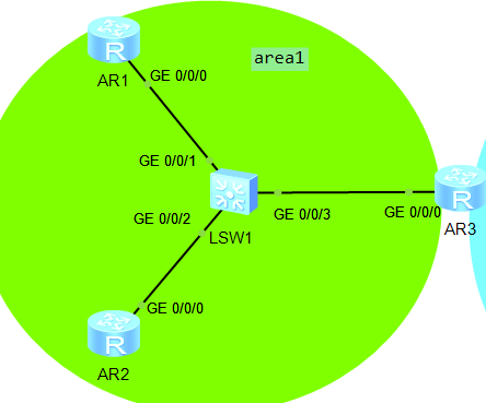
Experimental topology:

IP planning:
172.16.0.0/16
Because six areas are required, IP is divided into six network segments, 2 ^ 3 = 8. Some sub network segments are further divided, and appropriate network segments are allocated on P2P backbone links, MA backbone links and other routers
172.16.0.0/16
Six areas are required
172.16.0.0/19 area0
172.16.0.0/25 172.168.0.128/25 172.168.1.0/25 172.168.1.128...
172.16.0.0/25 p2p backbone link 172.16.0.0/30 172.16.0.4/30
172.16.0.128/25 MA backbone link 172.16.0.128, 29 172.16.0.136/29
172.16.32.0/19
172.16.64.0/19
172.16.96.0/19
172.16.128.0/19
172.16.160.0/19
172.16.192.0/19
172.16.224.0/19
Configure area0 area first
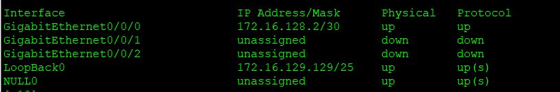
1,Configure the interface first IP
[r3-GigabitEthernet0/0/1]ip add 34.1.1.1 24

[r4-GigabitEthernet0/0/0]ip add 34.1.1.2 24
[r4-GigabitEthernet0/0/1]ip add 45.1.1.2 24
[r4-GigabitEthernet0/0/2]ip add 46.1.1.2 24
[r4-GigabitEthernet4/0/0]ip add 47.1.1.2 24

[r5-GigabitEthernet0/0/0]ip add 45.1.1.1 24

[r6-GigabitEthernet0/0/0]ip add 46.1.1.1 24

[r7-GigabitEthernet0/0/0]ip add 47.1.1.1 24
2,Configure default routes
[r3]ip route-static 0.0.0.0 0 34.1.1.2
[r5]ip route-static 0.0.0.0 0 45.1.1.2
[r6]ip route-static 0.0.0.0 0 46.1.1.2
[r7]ip route-static 0.0.0.0 0 47.1.1.2

with r4 For the central site, configure mgre
[r3]int t0/0/0
[r3-Tunnel0/0/0]ip add 172.16.0.129 24
[r3-Tunnel0/0/0]tunnel-protocol gre p2mp
[r3-Tunnel0/0/0]source 34.1.1.1
[r3-Tunnel0/0/0]nhrp entry multicast dynamic
[r3-Tunnel0/0/0]nhrp network-id 100
[r3-Tunnel0/0/0]ip add 172.16.0.129 29

[r5]int t0/0/0
[r5-Tunnel0/0/0]ip add 172.16.0.130 29
[r5-Tunnel0/0/0]tunnel-protocol gre p
[r5-Tunnel0/0/0]tunnel-protocol gre p2mp
[r5-Tunnel0/0/0]source g0/0/0
[r5-Tunnel0/0/0]nhrp ent 172.16.0.129 34.1.1.1 register
[r5-Tunnel0/0/0]nhrp network-id 100

[r6]int t0/0/0
[r6-Tunnel0/0/0]ip add 172.16.0.131 29
[r6-Tunnel0/0/0]tunnel-protocol gre p2mp
[r6-Tunnel0/0/0]source g0/0/0
[r6-Tunnel0/0/0]nhrp entry 172.16.0.129 34.1..1.1 register
[r6-Tunnel0/0/0]nhrp network-id 100

[r7]int t0/0/0
[r7-Tunnel0/0/0]ip add 172.16.0.132 29
[r7-Tunnel0/0/0]tunnel-protocol gre p2mp
[r7-Tunnel0/0/0]source g0/0/0
[r7-Tunnel0/0/0]nhrp entry 172.16.0.129 34.1.1.1 register
[r7-Tunnel0/0/0]nhrp network-id 100
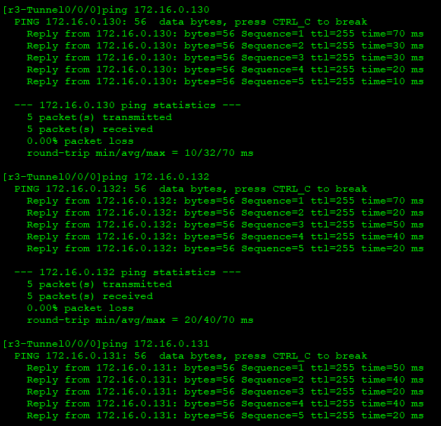
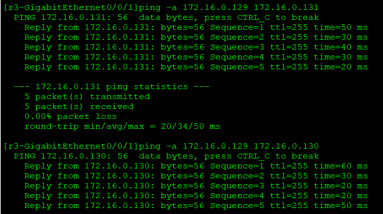
test
Ping the private address of R5 / R6 / R7 on r3
nat on R3, R5, R6 and R7
[r5]acl 2000
[r5-acl-basic-2000]rule permit source any
[r5-acl-basic-2000]int g0/0/0
[r5-GigabitEthernet0/0/0]nat outbound 2000
The other three are the same
Test:
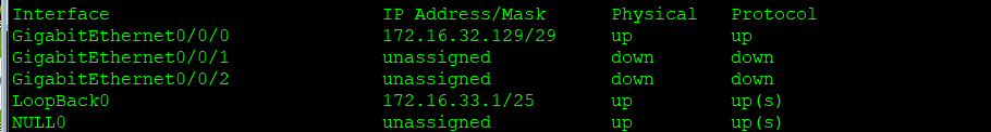
Configure IP and loopback interfaces
area0
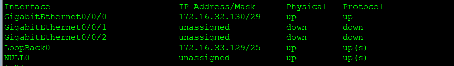
r1
r2:
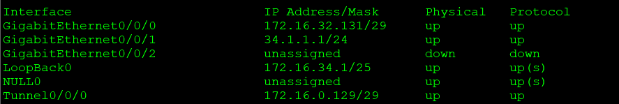
r3:
area2:
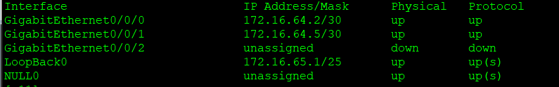
r6

R11:
R12:

area3
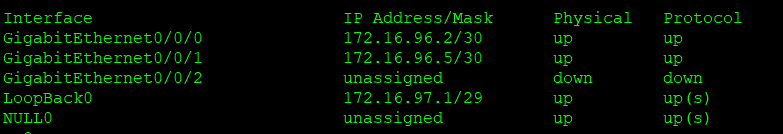
R7:

R8:
R9:

area4:
R9:

R10:
area5
R12

Start OSPF protocol and configure Area 0/1/2/3/4; And configure rip protocol
[r1]ospf 1 router-id 1.1.1.1
[r1-ospf-1]area 1
[r1-ospf-1-area-0.0.0.1]network 172.16.0.0 0.0.255.255

[r2]ospf 1 router-id 2.2.2.2
[r2-ospf-1]area 1
[r2-ospf-1-area-0.0.0.1]  network 172.16.0.0 0.0.255.255

[r3]ospf 1 router-id 3.3.3.3
[r3-ospf-1]area 1
[r3-ospf-1-area-0.0.0.1]net 172.16.32.0 0.0.3.255
[r3-ospf-1-area-0.0.0.1]area 0
[r3-ospf-1-area-0.0.0.0]net 172.16.0.129 0.0.0.0

[r5]ospf 1 router-id 5.5.5.5
[r5-ospf-1]area 0
[r5-ospf-1-area-0.0.0.0]net 172.16.0.0 0.0.255.255

[r6]ospf 1 router-id 6.6.6.6
[r6-ospf-1]area 0
[r6-ospf-1-area-0.0.0.0]net 172.16.0.0 0.0.1.255
[r6-ospf-1-area-0.0.0.1]area 2
[r6-ospf-1-area-0.0.0.2]net 172.16.64.1 0.0.0.0

[r7]ospf 1 router-id 7.7.7.7
[r7-ospf-1]area 0
[r7-ospf-1-area-0.0.0.0]net 172.16.0.0 0.0.3.255
[r7-ospf-1-area-0.0.0.0]area 3
[r7-ospf-1-area-0.0.0.3]net 172.16.96.1 0.0.0.0

[r8]ospf 1 router-id  8.8.8.8
[r8-ospf-1]area 3
[r8-ospf-1-area-0.0.0.3]net 172.16.0.0 0.0.255.255

[r9]ospf 1 router-id  9.9.9.9
[r9-ospf-1]area 3
[r9-ospf-1-area-0.0.0.3]network 172.16.96.6 0.0.0.0
[r9-ospf-1-area-0.0.0.3]area 4
[r9-ospf-1-area-0.0.0.4]net 172.16.128.0 0.0.1.255

[r10]ospf 1 router-id
[r10]ospf 1 router-id 10.10.10.10
[r10-ospf-1]area 4
[r10-ospf-1-area-0.0.0.4]net 172.16.0.0 0.0.255.255

[r11]ospf 1 router-id 11.11.11.11
[r11-ospf-1]area 2
[r11-ospf-1-area-0.0.0.2]net 172.16.0.0 0.0.255.255

[r12]ospf 1 router-id 12.12.12.12
[r12-ospf-1]area 2
[r12-ospf-1-area-0.0.0.2]net 172.16.64.6 0.0.0.0
[r12]rip 1
[r12-rip-1]v 2
[r12-rip-1]net 172.16.0.0

take RIP Republish to OSPF Medium;
[R12]ospf 1
[R12-ospf-1]import-route rip 1
Check whether the neighbor relationship is established:

Modify the interface network type of MGRE environment and change the Dr priority of R5, 6 and 7 to 0
[R3]interface Tunnel 0/0/0
[R3-Tunnel0/0/0]ospf network-type broadcast

[R5]interface Tunnel 0/0/0
[R5-Tunnel0/0/0]ospf network-type broadcast
[R5-Tunnel0/0/0]ospf dr-priority 0
Testing;
At this time, all protocols are configured and the test is started;
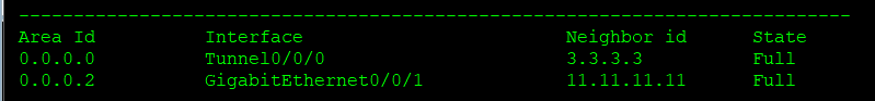
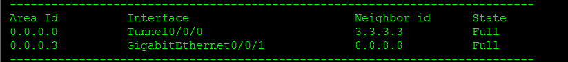
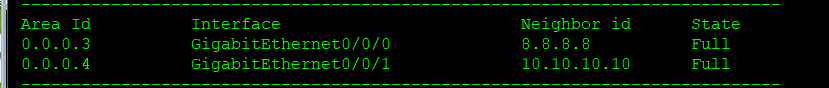
View neighbor relationships at key locations;
Neighbor relationship table of r3

Neighbor relationship table of r6
Neighbor relationship table of r7
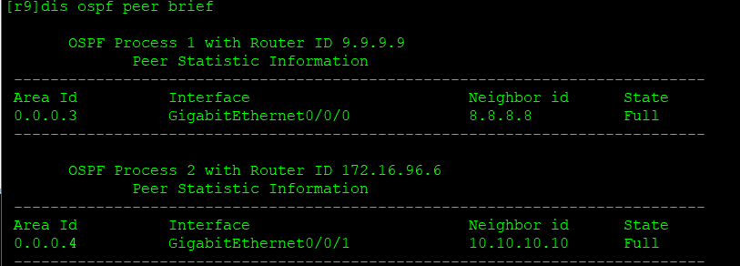
Neighbor relationship table of r9
Solve the communication problem between area 3 and area 4 (generally recommended to reissue);
[R9]undo ospf 1
Warning: The OSPF process will be deleted. Continue? [Y/N]:y
[R9]ospf 1 router-id 9.9.9.9
[R9-ospf-1]area 3
[R9-ospf-1-area-0.0.0.3]network 172.16.96.6 0.0.0.0
[R9-ospf-1-area-0.0.0.3]ospf 2
[R9-ospf-2]area 4
[R9-ospf-2-area-0.0.0.4]net 172.16.128.0 0.0.0.255
Now our OSPF 1 is equivalent to the original Area 3, and OSPF 2 is equivalent to the original Area 4;
Then we can republish OSPF 2 to OSPF 1! There is no need for two-way republication, because finally, just issue a default to OSPF 2!
[R9]ospf 1
[R9-ospf-1]import-route ospf  2
View neighbor table:
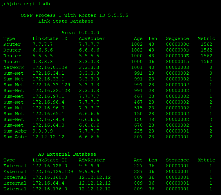
To view the link status database:
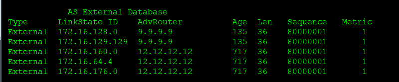
Link state database for R5:
Next, we reduce the update amount of lsa and summarize it on the abr of each region
[r3]ospf 1
[r3-ospf-1]area 1
[r3-ospf-1-area-0.0.0.1]abr-summary 172.16.32.0 255.255.224.0

[r6]ospf 1
[r6-ospf-1]area 2
[r6-ospf-1-area-0.0.0.2]abr-summary 172.16.64.0 255.255.224.0

[r7]ospf 1
[r7-ospf-1]area 3
[r7-ospf-1-area-0.0.0.3]abr-summary 172.16.96.0 255.255.224.0

[r9]ospf 1
[r9-ospf-1]asbr-summary 172.16.128.0 255.255.224.0

[r12]ospf 1
[r12-ospf-1]asbr-summary 172.16.160.0 255.255.224.0
Now the LSDB in the backbone area has been reduced to the minimum;
Then configure special areas to continue to reduce:
Region 1 can be a stub region:
[R1]ospf 1
[R1-ospf-1]area 1
[R1-ospf-1-area-0.0.0.1]stub
[R2-ospf-1]area 1
[R2-ospf-1-area-0.0.0.1]stub
[R3-ospf-1-area-0.0.0.1]stub no-summary
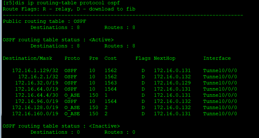
View the summarized routing information on R5:
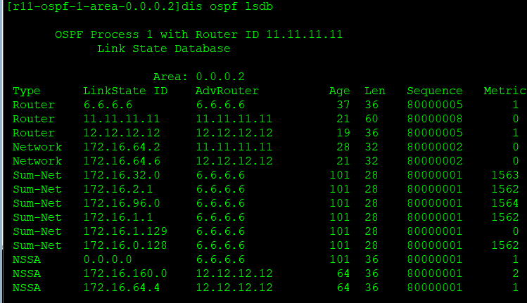
Zone 2 can be an nssa zone:
[R6-ospf-1-area-0.0.0.2]nssa
[R11-ospf-1-area-0.0.0.2]nssa
[R12-ospf-1-area-0.0.0.2]nssa
Zone 2 can be a full nssa zone:
[R6-ospf-1-area-0.0.0.2]nssa no-summary
Three types of lsa default:
[R7-ospf-1-area-0.0.0.3]nssa no-summary
[R8-ospf-1-area-0.0.0.3]nssa
[R9-ospf-1-area-0.0.0.3]nssa
Solve the communication problems between area 4 and other areas, and delegate default routing to area 4;
[R9-ospf-2]default-route-advertise
We went back to R5 to check ospf routes and found that the number of routes was greatly reduced.

Achieve the ultimate goal!