The most important task this week is to write the CIR estimation of multipath effect, so the idea process is collected in a blog for future reference
1 topic interpretation
First of all, I can't understand the task topic. What is CIR estimation?
When I asked my sister about the channel impulse response, I suddenly thought of the channel estimation I had heard before. Baidu Encyclopedia explained the channel estimation as follows:
The so-called channel estimation is the process of estimating the model parameters of a hypothetical channel model from the received data. If the channel is linear, channel estimation is to estimate the impulse response of the system. It should be emphasized that channel estimation is a mathematical representation of the impact of the channel on the input signal, and "good" channel estimation is an estimation algorithm that minimizes some estimation error.
In other words, my task can be described as channel estimation for channels with multipath effects
There are two issues that need to be clarified:
(1) How to code the channel with multipath effect?
(2) How to write the channel estimation algorithm?
First of all, before starting the research, my understanding of the channel is as follows:
A communication system has several processes: coding, modulation, channel transmission, demodulation and decoding
Encode the data to be transmitted in order to increase the complexity and reduce the error rate
Modulation is to embed data into a carrier so that transmission can be realized
The channel in the communication model plays a sense of existence by adding noise interference, which makes demodulation and decoding errors
From my current understanding of communication system and channel, I can raise the following questions about the topic:
(1) What is the meaning of channel impulse response?
(2) What are the differences between multipath channels and other channels? In other words, what are the differences between different channels?
Question (1) can be answered by looking at it the next day
When learning signals and systems, we know that in a linear time invariant system, the output corresponding to all inputs can be regarded as a linear combination of impulse responses. Therefore, as long as we know the impulse response of the system, we can calculate the output by giving any input
The second problem is a little deep. Before exploring this problem, I think we can implement an ordinary channel estimation algorithm to feel it
8-30 update
By reading two papers on sound source localization, we can make a preliminary definition. The so-called channel estimation is the process of obtaining the channel transfer function H, which is a function of attenuation and delay
2 channel estimation
according to 2 Why channel estimation?
It is to compensate the channel at the receiver, so as to improve the performance of the whole system.
"MIMO-OFDM Wireless Communication Technology and MATLAB implementation" has a special chapter on channel estimation
Channel estimation generally uses preamble or pilot pilot
There are three pilot structures:
(1) Block type: suitable for frequency selective channels
(2) Comb type: suitable for fast fading channels
(3) Lattice type
Channel estimation based on training symbols
Training symbol estimation needs to send preamble or pilot signal, which will generate additional load and reduce transmission efficiency.
When training symbols are used, least square (LS) or minimum mean square error (MMSE) techniques are generally used for channel estimation
LS method, the LS channel estimation on each subcarrier can be expressed as
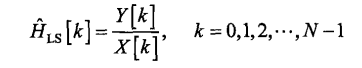
Where Y is the output and X is the input
LS method can enhance noise, but it is widely used because of its simplicity
The next pile of formula derivation is incomprehensible
According to the communication with my tutor, LS and MMSE are not enough for multipath channels, and I am recommended to read the following two papers:
[intensive literature reading] [communication] Symphony: Localizing Multiple Acoustic Sources with a Single Microphone Array
After reading these two papers, I was still confused. Because the topic of these two papers is sound source localization, I only briefly introduced the model of multipath channel, not the channel estimation algorithm
This post details the channel estimation code of OFDM system
Analysis and implementation of channel estimation technology in OFDM
I typed the code of this post myself, and there were one or two small bug s, but the process was very clear. After coding myself, I felt full of joy. The detailed comment version I wrote is as follows:
close all;
clear;
clc;

% Print only in the command line window
fprintf('OFDM Channel estimation simulation\n');

%% Parameter setting

carrier_count = 64;  % single OFDM Number of carriers in symbol
num_symbol = 50;     % OFDM Number of symbols, excluding pilots
guard = 8;           % Cyclic prefix CP, That is, each OFDM The last 8 subcarriers are used as CP Add at the beginning
pilot_inter = 8;     % Pilot interval, i.e. every few OFDM The symbol inserts a pilot
modulation_mode = 16;% modulation mode , QAM Modulated order
SNR = 0:2:20;        % SNR value
num_loop = 15;       % Number of cycles

% Do 15 experiments for each signal-to-noise ratio
num_bit_err = zeros(length(SNR), num_loop);
num_bit_err_dft = zeros(length(SNR), num_loop);
num_bit_err_ls = zeros(length(SNR), num_loop);
MSE = zeros(length(SNR), num_loop);
MSE_dft = zeros(length(SNR), num_loop);
MSE_ls = zeros(length(SNR), num_loop);

%% main program

for c1 = 1:length(SNR)
    fprintf('\n\n\n The simulation signal-to-noise ratio is%f\n\n', SNR(c1));
    for num1 = 1:num_loop
        %---------------Generate the transmitted random sequence-----------------------

        bits_len = carrier_count * num_symbol;
        bits_tx = randi([0 1], 1, bits_len); % 1 that 's ok bits_len Column matrix

        %---------------Symbol modulation-----------------------

        modulated_sequence = qammod(bits_tx, modulation_mode);

        %---------------Pilot format-----------------------

        pilot_len = carrier_count; % Pilot and OFDM Same level of symbols
        % rand Default interval (0, 1)
        % round rounding
        % After the end pilot_symbols There are only 0 and 1, which is a 1 line pilot_len Column matrix
        pilot_symbols = round(rand(1, pilot_len));

        % Change 0 in the pilot signal to-1,So there are two types of pilots at present,-1 And 1
        for i = 1:pilot_len
            if pilot_symbols(1, i) == 0
                pilot_symbols(1, i) = pilot_symbols(1, i) - 1;
            else
                pilot_symbols(1, i) = pilot_symbols(1, i);
            end
        end

        % Row vector to column vector
        pilot_symbols = pilot_symbols';

        %---------------Calculate the number of pilots and data-----------------------

        % ceil Round up
        num_pilot = ceil(num_symbol / pilot_inter);
        % rem Remainder, return num_symbol divide pilot_inter Remainder after
        % Each group of symbols starts with a pilot and ends with another pilot
        if rem(num_symbol, pilot_inter)==0
            num_pilot = num_pilot + 1;
        end

        num_data = num_symbol + num_pilot;

        %---------------Pilot position calculation-----------------------

        pilot_index = zeros(1, num_pilot);
        % +1 Is the position of the pilot, at this time data_index Capacity greater than num_symbol
        data_index = zeros(1, num_pilot * (pilot_inter + 1));
        for i = 1:num_pilot-1
            pilot_index(1, i) = (i-1) * (pilot_inter + 1) + 1;
        end
        % The position of the last pilot from the beginning depends on the specific situation
        % But at the last
        pilot_index(1, num_pilot) = num_data;

        % In order to insert the pilot, the first, last and every 8 bits of the index are empty
        % Missing index value at pilot_index
        for j = 0:num_pilot
            data_index(1, (1 + j * pilot_inter) : (j + 1) * pilot_inter) = (2 + j * (pilot_inter + 1)) : ((j + 1) * (pilot_inter + 1));
        end

        % Remove excess capacity
        data_index = data_index(1, 1:num_symbol);

        %---------------Pilot insertion-----------------------

        % Unlike before, each column is one OFDM Modulation symbol
        piloted_ofdm_syms = zeros(carrier_count, num_data);

        % piloted_ofdm_syms And modulated_sequence The number of columns is different
        % piloted_ofdm_syms The number of columns increases the number of pilots
        % and modulated_sequence The number of columns is only OFDM Number of symbols

        % First modulated_sequence It should be OFDM The number of columns of the symbol is inserted in turn modulated_sequence Columns of
        % data_index and modulated_sequence The number of columns is num_symbol
        piloted_ofdm_syms(:, data_index) = reshape(modulated_sequence, carrier_count, num_symbol);
        % Again pilot Insert its index bit
        % pilot_symbols Just a column vector, lateral expansion num_pilot Times into an array
        piloted_ofdm_syms(:, pilot_index) = repmat(pilot_symbols, 1, num_pilot);

        %---------------IFFT Transformation-----------------------

        % OFDM After modulation, the default is frequency domain signal
        % Why multiply sqrt(carrier_count)
        time_signal = sqrt(carrier_count) * ifft(piloted_ofdm_syms);

        %---------------Add cyclic prefix-----------------------

        % CP Same level as subcarrier
        add_cyclic_signal = [time_signal((carrier_count - guard + 1 : carrier_count), :); time_signal];
        % The matrix is transformed into a row vector and then transmitted
        tx_data_trans = reshape(add_cyclic_signal, 1, (carrier_count + guard) * num_data);

        %---------------Channel processing-----------------------

        % AWGN channel

        % Calculate signal power
        tx_signal_power = sum(abs(tx_data_trans(:)) .^ 2) / length(tx_data_trans(:));
        % Why?
        noise_var = tx_signal_power / (10 ^ (SNR(c1) / 10));
        rx_data = awgn(tx_data_trans, SNR(c1), 'measured');

        %---------------Signal reception, de cyclic prefix FFT Transformation-----------------------

        % Signal reception
        rx_signal = reshape(rx_data, (carrier_count + guard), num_data);
        % remove CP
        rx_signal_matrix = zeros(carrier_count, num_data);
        rx_signal_matrix = rx_signal(guard + 1:end, :);
        % FFT Transformation
        % Because the pilot is to be extracted next, the pilot naturally has to go back to the frequency domain to be extracted
        rx_carriers = fft(rx_signal_matrix) / sqrt(carrier_count);

        %---------------Pilot and data extraction-----------------------

        % Extract pilot
        rx_pilot = rx_carriers(:, pilot_index);
        % Extract data(frequency domain)
        rx_fre_data = rx_carriers(:, data_index);

        %---------------Pilot position channel response LS estimate-----------------------

        % pilot_patt It is inserted by the sender pilot
        pilot_patt = repmat(pilot_symbols, 1, num_pilot);
        % LS Algorithmic y/x
        pilot_esti = rx_pilot ./ pilot_patt;

        %---------------LS Linear interpolation of estimation-----------------------

        % Using channel estimation is already default rx of data Is not credible
        % Therefore, it is necessary to use pilot to recover data

        int_len = pilot_index;
        len = 1:num_data;
        channel_H_ls = zeros(carrier_count, num_data);

        % Each symbol/The number of subcarriers of the pilot is fixed
        % Now it's time to pass num_pilot A pilot to estimate num_data Pilots+data
        % Therefore, subcarriers come one by one
        for ii = 1:carrier_count
            % stay int_len(pilot_index)These points (the number of points is num_pilot)
            % Function values are pilot_esti(ii, 1:(num_pilot))
            % So the same function expands the point to len(num_data)What is the estimated value of each point?
            channel_H_ls(ii, :) = interp1(int_len, pilot_esti(ii, 1:(num_pilot)), len, 'linear');
        end

        channel_H_data_ls = channel_H_ls(:, data_index);

        %---------------LS The estimated value of the data sent in the estimation-----------------------

        % Where this formula comes from is still unknown
        tx_data_estimate_ls = rx_fre_data .* conj(channel_H_data_ls) ./ (abs(channel_H_data_ls) .^ 2);

        %---------------DFT estimate------------

        % DFT I guess it's for another ls Based on this, the time domain noise is eliminated
        % However, the following code does not understand why it can eliminate time-domain noise
        % Perhaps the number of points exceeding the subcarrier length is made in the time domain FFT Can you eliminate noise?

        % First pilot_esti Change to time domain
        % Supplementary subcarrier padding After( symbol Latitude unchanged)
        % Switch back to the frequency domain
        % plus padding Actually, I did carrier_count+1024 spot FFT Transformation
        tx_pilot_estimate_ifft = ifft(pilot_esti);
        padding_zero = zeros(1024, num_pilot);
        tx_pilot_estimate_ifft_padding_zero = [tx_pilot_estimate_ifft; padding_zero];
        % For matrices, fft Each column is separately fft
        tx_pilot_estimate_dft = fft(tx_pilot_estimate_ifft_padding_zero);

        %---------------DFT Linear interpolation of estimation------------

        % Interpolation operation and ls equally

        int_len = pilot_index;
        len = 1:num_data;
        channel_H_dft = zeros(carrier_count, num_data);

        for ii = 1:carrier_count
            channel_H_dft(ii, :) = interp1(int_len, tx_pilot_estimate_dft(ii, 1:(num_pilot)), len, 'linear');
        end

        channel_H_data_dft = channel_H_dft(:, data_index);

        %---------------DFT The estimated value of the data sent in the estimation------------

        tx_data_estimate_dft = rx_fre_data .* conj(channel_H_data_dft) ./ (abs(channel_H_data_dft) .^ 2);

        %---------------DFT Symbol demodulation------------

        % Each column vector of the original matrix becomes a row vector
        % And laid in order sequence
        demod_in_dft = tx_data_estimate_dft(:).';
        demod_out_dft = qamdemod(demod_in_dft, modulation_mode);

        %---------------LS Symbol demodulation------------

        demod_in_ls = tx_data_estimate_ls(:).';
        demod_out_ls = qamdemod(demod_in_ls, modulation_mode);

        %---------------Bit error rate calculation------------

        for i = 1:length(bits_tx)
            if demod_out_dft(i) ~= bits_tx(i)
                num_bit_err_dft(c1, num1) = num_bit_err_dft(c1, num1) + 1;
            end
            if demod_out_ls(i) ~= bits_tx(i)
                 num_bit_err_ls(c1, num1) = num_bit_err_ls(c1, num1) + 1;

            end
        end
    end
end

% num_bit_err_dft.'Indicates that the original row becomes a column
% Originally, each line represented one SNR All of loop result
% Now it becomes each column
% And num_bit_err_dft(:).'Expand differently, num_bit_err_dft.'Still matrix
% because mean The average is calculated by column
BER_dft = mean(num_bit_err_dft.') / length(bits_tx);
BER_ls = mean(num_bit_err_ls.') / length(bits_tx);

%% mapping
figure
semilogy(SNR, BER_dft, '-mp', SNR, BER_ls, '-k+');
title('OFDM Systematic LS and DFT Channel estimation');
xlabel('SNR');
ylabel('BER');
legend('DFT Channel estimation','LS Channel estimation');
Through this coding, I mainly understand the following important knowledge points:
(1) Pilot, the true face of CP
The pilot pilot pilot is at the same level as the symbol, and a pilot is inserted every few symbols
Update, the pilot can also be at the same level as the subcarrier, and there are many pilot insertion methods
The cyclic prefix CP is at the same level as the subcarrier. The last n subcarriers of each symbol are copied and inserted into the beginning as CP
For example, if a symbol [1, 2, 3, 4, 5] assumes that CP is 2, it becomes [4, 5, 1, 2, 3, 4, 5] after adding CP
(2) Understand the real purpose of pilot
Using channel estimation, in fact, it has been defaulted that rx data is untrusted, so it is necessary to use a pilot that is not easy to be disturbed to obtain the impact of the channel on the signal, that is, h, and then obtain the trusted data through the operation of rx and H
(3) DFT estimation is to convert the pilot ifft back to the time domain on the basis of LS, and then make N-point fft back to the frequency domain (n is greater than the number of carriers)
Moreover, through this coding, it is clear where the problem I don't understand is
To do XXX channel estimation, two problems need to be solved
(1) Model this channel
How much noise, attenuation, delay? In what way?
(2) Select the appropriate estimation algorithm
If y = hx + n, then ls, mmse, dft
Jam point:
(1) The multipath channel model is given in the wechat paper. How to implement the code?
It looks like y = hx + n. why ls doesn't work?
(2) I don't know where to find the appropriate estimation algorithm
Reference
[1] Computer simulation of impulse response of mobile wireless channel