Record the problems and solutions encountered in the development of Qt learning
Environment: qt5.12.9 qtcreater4.12.2 mingw7.3.0
Considering the low efficiency of using OpenGL fixed pipeline to draw images, I have always wanted to learn to use OpenGL ES2.0 for image rendering. There are not enough reference materials on the Internet, and I lack the foundation of OpenGL. I am completely groping and learning step by step. It is suggested that comrades with poor foundation of OpenGL, like me, come first https://learnopengl-cn.github.io/ Self study on this website, especially from the part of "Introduction - Hello, triangle", which is really very clear. We must study patiently.
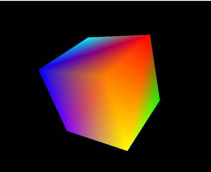
No nonsense, let's get to the point and record my program to realize the color cube.
1. First paste the glsl code
First part of the vertex shader, then part of the clip shader.
const char *vshader_code =
        "uniform mat4 mvp_matrix;                 \n"
        "attribute vec4 vPosition;                \n"
        "attribute vec3 aColor;                   \n"
        "varying vec3 vColor;                     \n"
        "void main()                              \n"
        "{                                        \n"
        "    gl_Position = mvp_matrix * vPosition; \n"
        "    vColor = aColor;                     \n"
        "}                                        \n";

const char *fshader_code =
        "varying vec3 vColor;                     \n"
        "void main()                              \n"
        "{                                        \n"
        "    gl_FragColor = vec4(vColor,1.0f);    \n"
        "}
Because this part of the code is too small, it is not saved as a glsl file. This part of the content will not be introduced in detail. If you don't clearly browse the website I wrote above for learning.
2. Color cube definition part code
#include "cubegeometry.h"

CubeGeometry::CubeGeometry():QOpenGLFunctions()
    , indexBuf(QOpenGLBuffer::IndexBuffer)
{
    initializeOpenGLFunctions();
    this->arrayBuf.create();
    this->indexBuf.create();
    initCubeGeometry();
}

CubeGeometry::~CubeGeometry()
{
    this->arrayBuf.destroy();
    this->indexBuf.destroy();
}

void CubeGeometry::drawCubeGeometry(QOpenGLShaderProgram *program)
{
    this->arrayBuf.bind();
    this->indexBuf.bind();

    quintptr offset = 0;

    // Tell OpenGL programmable pipeline how to locate vertex position data
    int vPos = program->attributeLocation("vPosition");
    program->enableAttributeArray(vPos);
    program->setAttributeBuffer(vPos, GL_FLOAT, offset, 3, sizeof(VertexData));

    // Offset for texture coordinate
    offset += sizeof(QVector3D);

    // Tell OpenGL programmable pipeline how to locate vertex texture coordinate data
    int aColor = program->attributeLocation("aColor");
    program->enableAttributeArray(aColor);
    program->setAttributeBuffer(aColor, GL_FLOAT, offset, 3, sizeof(VertexData));

    glDrawElements(GL_TRIANGLES, 36, GL_UNSIGNED_SHORT, 0);
}

void CubeGeometry::initCubeGeometry()
{
    //A cube has eight vertices, which define the vertex position and vertex color respectively
    VertexData vertices[] = {
        {QVector3D( 1.0f,  1.0f,  1.0f), QVector3D(1.0f, 0.0f, 0.0f)},  // v0, a-red
        {QVector3D(-1.0f,  1.0f,  1.0f), QVector3D(1.0f, 0.5f, 0.0f)},  // v1, b-orange
        {QVector3D(-1.0f, -1.0f,  1.0f), QVector3D(1.0f, 1.0f, 0.0f)},  // v2, c-yellow
        {QVector3D( 1.0f, -1.0f,  1.0f), QVector3D(0.0f, 1.0f, 0.0f)},  // v3, d-green
        {QVector3D( 1.0f,  1.0f, -1.0f), QVector3D(0.0f, 1.0f, 1.0f)},  // v4, e-sky
        {QVector3D(-1.0f,  1.0f, -1.0f), QVector3D(0.0f, 0.0f, 1.0f)},  // v5, f-blue
        {QVector3D(-1.0f, -1.0f, -1.0f), QVector3D(0.5f, 0.0f, 1.0f)},  // v6, g-purple
        {QVector3D( 1.0f, -1.0f, -1.0f), QVector3D(1.0f, 1.0f, 1.0f)},  // v7, h-white
    };

    //A square is composed of two triangles, because drawing a cube actually needs to draw 12 triangles. The following definition is the vertex position index of 12 triangles
    GLushort indices[] = {
           0,1,2,
           0,2,3,
           4,0,3,
           4,3,7,
           5,4,7,
           5,7,6,
           1,5,6,
           1,6,2,
           5,1,0,
           5,0,4,
           6,7,3,
           6,3,2
       };

    this->arrayBuf.bind();
    this->arrayBuf.allocate(vertices, 8 * sizeof(VertexData));
    this->arrayBuf.setUsagePattern(QOpenGLBuffer::StaticDraw);

    this->indexBuf.bind();
    this->indexBuf.allocate(indices, 36 * sizeof(GLushort));
    this->indexBuf.setUsagePattern(QOpenGLBuffer::StaticDraw);
}
#ifndef CUBEGEOMETRY_H
#define CUBEGEOMETRY_H
#include <QOpenGLBuffer>
#include <QOpenGLFunctions>
#include <QOpenGLShaderProgram>

struct VertexData
{
    QVector3D position;    //Vertex Position
    QVector3D color;       //Vertex Color
};

class CubeGeometry : public QOpenGLFunctions
{
public:
    CubeGeometry();
    ~CubeGeometry();

    void drawCubeGeometry(QOpenGLShaderProgram *program);\

private:
    void initCubeGeometry();

    QOpenGLBuffer arrayBuf;   //VBO
    QOpenGLBuffer indexBuf;   //IBO
};

#endif // CUBEGEOMETRY_H
Take a look at the display of the cube
3. Display and control operation
First, create a GLWidget class to inherit qoopenglwidget and qoopenglfunctions. Then create the interface file, select Add QWidget object, and promote the changed object to GLWidget. In this way, you will get an interface that can be used to display the cube.
There are three commonly used perspective methods in OpenGL for inserting a content. Different perspective functions are used accordingly. I won't expand and write here. The perspective method is used in my code, and the corresponding perspective method is shown in the figure below.
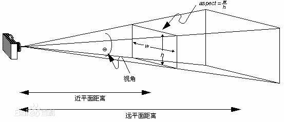
In addition, when using OpenGL, you need to pay attention to the selection of reference coordinate system, because the scaling, rotation and translation of objects in three-dimensional space are the operation of spatial coordinates. Usually, the center of the observed object is selected as the center point to establish the coordinate system.
Zoom rendering
Rotation rendering
Drag and move rendering
The code part of the GLWidget class. h file
#ifndef GLWIDGET_H
#define GLWIDGET_H

#include <QObject>
#include <QOpenGLWidget>
#include <QOpenGLFunctions>
#include <QOpenGLBuffer>
#include <QOpenGLShaderProgram>
#include <QVector3D>
#include <QWheelEvent>
#include <QMouseEvent>
#include "cubegeometry.h"

//This structure is used to define the relevant information of the observer's perspective
typedef  struct
{
    float     distance;    //The initial distance between the observer and the center of the observed object
    float     fovy;        //The size of the observer's perspective
    float     zoom;        //Multiple of the distance between the observer and the center point of the observed object, which is used for zoom control
    QVector3D  eye;        //The position of the observer in the three-dimensional coordinate system of the observed object
    QVector3D  center;     //The coordinate of the center point of the observed object is [0,0,0]
    QVector3D  up;         //The observer's head is facing
}CameraView;

class GLWidget : public QOpenGLWidget, protected QOpenGLFunctions
{
    Q_OBJECT
public:
    GLWidget(QWidget *parent = nullptr);
    ~GLWidget();
    void Rotate(QMatrix4x4 matrix);

protected:
    void initializeGL() override;
    void paintGL() override;
    void resizeGL(int w, int h) override;
    void wheelEvent(QWheelEvent *event) override;
    void mousePressEvent(QMouseEvent *event) override;
    void mouseMoveEvent(QMouseEvent *event) override;
    void mouseReleaseEvent(QMouseEvent *event) override;

private:
    void initShaders();
    void initTextures();
    int setRotation(int angle);
    void normalizeAngle(int &angle);

private:
    CubeGeometry *cubeGeometry;
    QOpenGLShaderProgram *program;
    QMatrix4x4 projection;      //Perspective matrix
    QMatrix4x4 m_translation;   //translation matrix
    QMatrix4x4 m_rotation;   //Rotation matrix
    int m_MouseFlag;         //Record the mouse button pressed
    bool m_MousePressFlag;   //Record whether the mouse button has been pressed
    QPoint mousePressPosition;     //Record the coordinate position when the mouse is pressed
    CameraView Camera;      //Record data related to the observer's perspective
    int m_xRot;   //Record the angle of rotation about the x-axis
    int m_yRot;   //Record the angle of rotation about the y axis
    int m_zRot;   //Record the angle of rotation about the z axis
    qreal m_xTrans;  //Record the position along the x-axis
    qreal m_yTrans;  //Record the position along the y-axis
};
#endif // GLWIDGET_H
The code part of the GLWidget class. cpp file
#include "glwidget.h"
#include <QOpenGLShaderProgram>
#include <QDebug>
#include <QtMath>
#include <QQuaternion>
GLWidget::GLWidget(QWidget * parent) : QOpenGLWidget(parent)
      , cubeGeometry(0)
{
    this->m_MouseFlag = Qt::NoButton;
    this->m_MousePressFlag = false;
    this->m_xRot = 0;
    this->m_yRot = 0;
    this->m_zRot = 0;
    this->m_xTrans = 0;
    this->m_yTrans = 0;
}

GLWidget::~GLWidget()
{
    makeCurrent();
    delete  cubeGeometry;
    doneCurrent();
}

void GLWidget::Rotate(QMatrix4x4 matrix)
{
    this->m_rotation = matrix;
    update();
}

void GLWidget::initializeGL()
{
    initializeOpenGLFunctions();
    glClearColor(0, 0, 0, 1);

    initShaders();
    initTextures();

    // Enable depth buffer
    glEnable(GL_DEPTH_TEST);

    // Enable back face culling
    glEnable(GL_CULL_FACE);

    this->cubeGeometry = new CubeGeometry();

    Camera.distance = 5.0;
    Camera.fovy     = 45.0;
    Camera.zoom     = 1.0;
    //The observer position is in the negative direction of the z axis
    Camera.eye      = {0,0, Camera.zoom * Camera.distance};
    //Central coordinates of the observed object
    Camera.center   = {0.0,0.0,0.0};
    //The observer's head faces the y-axis
    Camera.up       = {0.0,1.0,0.0};
    //According to the above definition, after the interface is initialized, the coordinate system seen from the interface is that the center of the interface is the origin, the horizontal right is the positive half axis of x axis, the vertical up is the positive half axis of y axis, and the screen inward is the positive half axis of z axis
}

//Ensure that the display of objects in the interface is not deformed by the change of interface aspect ratio
void GLWidget::resizeGL(int w, int h)
{
    qreal aspect = qreal(w) / qreal(h ? h : 1);
    const qreal zNear = 0.001, zFar = 1000.0;
    projection.setToIdentity();
    // Get perspective matrix
    projection.perspective(Camera.fovy, aspect, zNear, zFar);
}

//Zoom control is to control the distance from the observer's position to the center of the observed object, that is, change the value of Camera.eye
void GLWidget::wheelEvent(QWheelEvent *event)
{
    if(this->m_MousePressFlag)
        return;
    if(event->angleDelta().y() > 0)
    {
        Camera.zoom -= 0.1;
    }else{
        Camera.zoom += 0.1;
    }
    if(Camera.zoom >= 3)
    {
        Camera.zoom = 3;
    }else if(Camera.zoom <= 0.1)
    {
        Camera.zoom = 0.1;
    }
    //Because the position of the observer I defined is on the z axis, only changing the z value of Camera.eye can achieve the object scaling effect
    Camera.eye.setZ(Camera.zoom * Camera.distance);
    update();
}
//Used to record the type of mouse down and the position when the mouse down
void GLWidget::mousePressEvent(QMouseEvent *event)
{
    if(event->button() & Qt::LeftButton)
    {
        this->m_MouseFlag = Qt::LeftButton;
    }else if(event->button() & Qt::RightButton)
    {
        this->m_MouseFlag = Qt::RightButton;
    }else if(event->button() & Qt::MidButton)
    {
        this->m_MouseFlag = Qt::MidButton;
    }
    this->m_MousePressFlag = true;
    this->mousePressPosition = event->pos();
}
//The corresponding processing operation is performed according to the amount of mouse movement and the mouse type
void GLWidget::mouseMoveEvent(QMouseEvent *event)
{
    QPoint diff = event->pos() - mousePressPosition;
    if(this->m_MouseFlag == Qt::LeftButton)
    {
        //Press the left mouse button and move to control the rotation of the observed object around the x-axis and y-axis
        this->m_xRot = setRotation(4 * diff.x());
        this->m_yRot = setRotation(4 * diff.y());
    }else if(this->m_MouseFlag == Qt::RightButton)
    {
        //Press the right mouse button and move to control the rotation of the observed object around the x-axis and z-axis
        this->m_xRot = setRotation(4 * diff.x());
        this->m_zRot = setRotation(4 * diff.y());
    }else if(this->m_MouseFlag == Qt::MidButton)
    {
        //Press the middle mouse button (i.e. scroll wheel) and move to realize the drag and translation of the observed object
        if(!this->m_MousePressFlag)
            return;
        //The following calculation is to project the distance of moving the mouse in the interface into the xoy plane of the observed object to obtain the actual distance that the object should move
        qreal w_h_ratio = (qreal)(this->width()) / (qreal)(this->height());
        qreal cube_view_height = 2 * Camera.zoom * Camera.distance *qTan(qDegreesToRadians(Camera.fovy/2));
        qreal cube_view_width = w_h_ratio * cube_view_height;

        this->m_xTrans = cube_view_width / qreal(this->width()) * qreal(diff.x());
        this->m_yTrans = cube_view_height / qreal(this->height()) * qreal(diff.y());
    }
    update();
}
//When the mouse is released, record the current rotation or translation matrix
void GLWidget::mouseReleaseEvent(QMouseEvent *event)
{
    if((event->button() & Qt::LeftButton) || (event->button() & Qt::RightButton))
    {
        this->m_MousePressFlag = false;
        QMatrix4x4 m;
        //Note here that due to the characteristics of Euler rotation, the rotation order of the object around the three axes is different, and the angle of the object obtained after the final rotation is different. Therefore, ensure that the order of the axes is the same for each rotation
        m.rotate(qreal(this->m_zRot)/16.0f, 0.0f, 0.0f, 1.0f);
        m.rotate(qreal(this->m_yRot)/16.0f, 0.0f, 1.0f, 0.0f);
        m.rotate(qreal(this->m_xRot)/16.0f, 1.0f, 0.0f, 0.0f);
        this->m_rotation = m * this->m_rotation;
        this->m_xRot = 0;
        this->m_yRot = 0;
        this->m_zRot = 0;
    }else if(event->button() & Qt::MidButton)
    {
        this->m_MousePressFlag = false;
        QMatrix4x4 m;
        m.translate(this->m_xTrans, -1.0*this->m_yTrans, 0);
        this->m_translation = m*this->m_translation;
        this->m_xTrans = 0;
        this->m_yTrans = 0;
    }
}
//Compile shaders and connect bindings
void GLWidget::initShaders()
{
    QOpenGLShader *vshader = new QOpenGLShader(QOpenGLShader::Vertex, this);
    if(!vshader->compileSourceCode(vshader_code))
    {
        qDebug()<<"vshader code error.";
    }

    QOpenGLShader *fshader = new QOpenGLShader(QOpenGLShader::Fragment, this);
    if(!fshader->compileSourceCode(fshader_code))
    {
        qDebug()<<"fshader code error.";
    }

    program = new QOpenGLShaderProgram();
    program->addShader(vshader);
    program->addShader(fshader);

    program->link();
    program->bind();
}

void GLWidget::initTextures()
{
}

int GLWidget::setRotation(int angle)
{
    normalizeAngle(angle);
    return angle;
}

void GLWidget::normalizeAngle(int &angle)
{
    while (angle < 0)
        angle += 360 * 16;
    while (angle > 360 * 16)
        angle -= 360 * 16;
}

void GLWidget::paintGL()
{
    glClear(GL_COLOR_BUFFER_BIT | GL_DEPTH_BUFFER_BIT);

    //Note here that the object must be rotated first, and then other transformations such as translation, scaling, etc
    //All transformations in three-dimensional space are realized through the left multiplication of the matrix (if you don't know about this part, you can check the data separately, ha), because the rotation matrix is the first to carry out the left multiplication of the object's spatial coordinates!
    QMatrix4x4 rotation;
    rotation.rotate(qreal(this->m_zRot)/16.0f, 0.0f, 0.0f, 1.0f);
    rotation.rotate(qreal(this->m_yRot)/16.0f, 0.0f, 1.0f, 0.0f);
    rotation.rotate(qreal(this->m_xRot)/16.0f, 1.0f, 0.0f, 0.0f);
    //The current rotation matrix is calculated
    rotation = rotation * this->m_rotation;

    QMatrix4x4 m1,m2;
    //Get the current observer matrix
    m1.lookAt(Camera.eye, Camera.center, Camera.up);
    m1 = m1 * rotation;
    //Get the current translation matrix
    m2.translate(this->m_xTrans, -1.0*this->m_yTrans, 0);
    m2 = m2 * this->m_translation;
    program->setUniformValue("mvp_matrix", projection * m2 * m1);

    this->cubeGeometry->drawCubeGeometry(program);
}