catalogue
preface
How to complete the experiment according to the experimental requirements?
Experimental requirements
1. Multipoint two-way republication between the two protocols
2. The loopback of R7 is not announced in the OSPF protocol, and is republished later
3. To solve the loop problem, all paths are selected optimally, and there is backup
experimental analysis
1. Plan the IP address according to the experimental topology and complete the underlying IP address configuration
IP Address and loopback address configuration

R1:

#
interface GigabitEthernet0/0/0
 ip address 12.1.1.1 255.255.255.0
#
interface GigabitEthernet0/0/1
 ip address 13.1.1.1 255.255.255.0

#
interface LoopBack0
 ip address 1.1.1.1 255.255.255.0

R2:

#
interface GigabitEthernet0/0/0
 ip address 12.1.1.2 255.255.255.0
#
interface GigabitEthernet0/0/1
 ip address 24.1.1.1 255.255.255.0

#
interface LoopBack0
 ip address 2.2.2.2 255.255.255.0

R3:

#
interface GigabitEthernet0/0/0
 ip address 13.1.1.2 255.255.255.0
 rip metricout ip-prefix 1 2
#
interface GigabitEthernet0/0/1
 ip address 34.1.1.1 255.255.255.0

#
interface LoopBack0
 ip address 3.3.3.3 255.255.255.0

R4:

#
interface GigabitEthernet0/0/0
 ip address 34.1.1.2 255.255.255.0
#
interface GigabitEthernet0/0/1
 ip address 24.1.1.2 255.255.255.0
#
interface GigabitEthernet0/0/2
 ip address 45.1.1.1 255.255.255.0

#
interface LoopBack0
 ip address 4.4.4.4 255.255.255.0


R5:

#
interface GigabitEthernet0/0/0
 ip address 45.1.1.2 255.255.255.0
#
interface GigabitEthernet0/0/1
 ip address 56.1.1.1 255.255.255.0

#
interface LoopBack0
 ip address 5.5.5.5 255.255.255.0


R6:

#
interface GigabitEthernet0/0/0
 ip address 56.1.1.2 255.255.255.0
#
interface GigabitEthernet0/0/1
 ip address 67.1.1.1 255.255.255.0

#
interface LoopBack0
 ip address 6.6.6.6 255.255.255.0


R7:

#
interface GigabitEthernet0/0/0
 ip address 67.1.1.2 255.255.255.0
#
interface GigabitEthernet0/0/1

#
interface LoopBack0
 ip address 7.7.7.7 255.255.255.0
Note: after the configuration is completed, ping the adjacent network segments of the router to verify that the underlying IP address is configured correctly.
2. Enable RIP and OSPF routing protocols on each device
to configure RIP OSPF

R1:

#
rip 1
 version 2
 network 1.0.0.0
 network 12.0.0.0
 network 13.0.0.0

R2:

#
ospf 1
 area 0.0.0.0
  network 24.1.1.0 0.0.0.255
#
rip 1
 version 2
 network 2.0.0.0
 network 12.0.0.0


R3:

#
ospf 1
 area 0.0.0.0
  network 3.3.3.3 0.0.0.0
  network 34.1.1.0 0.0.0.255
#
rip 1
 version 2
 network 13.0.0.0

R4:

#
ospf 1
 area 0.0.0.0
  network 4.4.4.4 0.0.0.0
  network 24.1.1.0 0.0.0.255
  network 34.1.1.0 0.0.0.255
  network 45.1.1.0 0.0.0.255

R5:

#
ospf 1
 area 0.0.0.0
  network 5.5.5.5 0.0.0.0
  network 45.1.1.0 0.0.0.255
  network 56.1.1.0 0.0.0.255

R6:

#
ospf 1
 area 0.0.0.0
  network 6.6.6.6 0.0.0.0
  network 56.1.1.0 0.0.0.255
  network 67.1.1.0 0.0.0.255

R7:

#
ospf 1
 area 0.0.0.0
  network 67.1.1.0 0.0.0.255
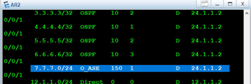
After configuration, the routing tables of R2 and R3 should have all routes except the loopback of R7
3. Republish the loopback of R7 into OSPF on R7
R7:

#
ospf 1
 import-route direct  ---take R7 The loop is redistributed as a direct interface
4. Do two-point two-way re release on R2 and R3
R2:

#
ospf 1
 import-route rip 1  ---take rip 1 Resend cloth in OSPF 1

#
rip 1
 import-route ospf 1 ----take OSPF 1 Resend cloth in RIP 1


R3:

#
ospf 1
 import-route rip 1  ---take rip 1 Resend cloth in OSPF 1

#
rip 1
 import-route ospf 1 ----take OSPF 1 Resend cloth in RIP 1
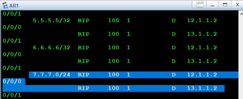
After the protocol is enabled, we will republish RIP and OSPF in both directions, and republish the R7 loop in the form of direct interface. At this time, we will find that on R1, according to the experimental topology, the loopback from R1 to R7 should be load balanced, but not here.
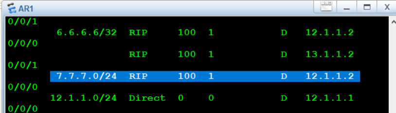
According to his next hop 12.1.1.2, let's look at the routing table on R2 and point to R4 on R2
We then look at the routing table on R4, but on R4, he points the next hop to R3. At this time, it indicates that the ring is out here.
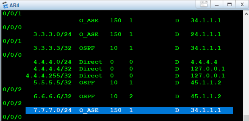
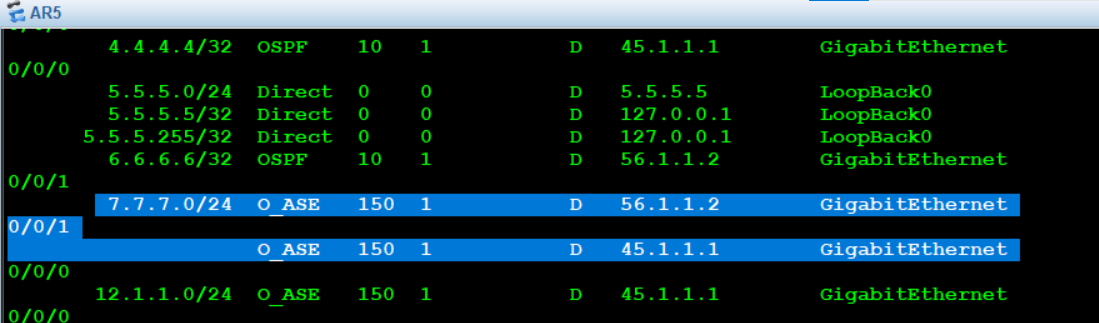
At the same time, on the routing table of R5, the routes from R5 to R7 are load balanced.
5. Solve the loop (modify priority)
Cause of loop:
When R7 publishes its direct route to the OSPF protocol, the preference of the route is 150. In Huawei equipment, the priority of OSPF is 10, the priority of RIP is 100, and the priority after republishing OSPF is 150. Therefore, after R7 republishes the route, R2 republishes it to the rip protocol, and then rip republishes it to the OSPF protocol after whitewashing, The priority of the original 150 is changed to 100, so the R4 router chooses to trust the route with priority of 100 issued by R3, resulting in a loop. Therefore, on R5, there is load balancing to R7, pointing to R4 and R6 respectively.
resolvent:
In CISCO, the method to solve this kind of problem is to increase the preference of out of loop routing so that it is not trusted by the router. Huawei equipment can also operate in this way:
R2:

#
ip ip-prefix a index 10 permit 7.7.7.0 24   ---Create a file named a The prefix list with sequence number 10 fetches traffic
#
route-policy a permit node 10  -----Create a file named a,Large actions are allowed, and the routing policy with sequence number 10
 if-match ip-prefix a     ------Matching name is a Prefix list for
 apply preference 151    ----- Define a small action as a modification priority of 151

#
rip 1
 preference route-policy a  ----get into RIP Call named a Routing policy modification priority


R3:

#
ip ip-prefix a index 10 permit 7.7.7.0 24

#
route-policy a permit node 10
 if-match ip-prefix a
 apply preference 151
#
rip 1
 preference route-policy a
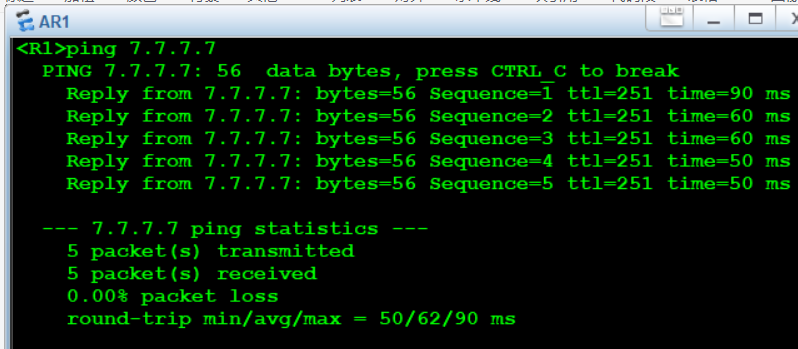
After the configuration is completed, we can see that R1-R7 is load balanced, the loop disappears, and you can ping to 7.7.7.7
6. Solve the suboptimal path
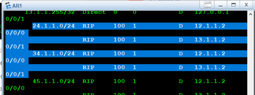
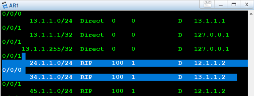
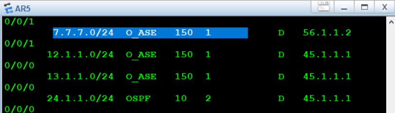
From the routing table of R1, network segments 24 and 34 are load balanced, but according to the experimental topology, it should not be load balanced
Routing Optimization: the best route is from R1 to 24 network segments, and the best route is from 34 network segments:
Specific configuration:
R2:

#
ip ip-prefix 1 index 10 permit 3.3.3.0 24
ip ip-prefix 1 index 20 permit 34.1.1.0 24
#
interface GigabitEthernet0/0/0
 rip metricout ip-prefix 1 2

R3:

#
ip ip-prefix 1 index 10 permit 24.1.1.0 24
#
interface GigabitEthernet0/0/0
 rip metricout ip-prefix 1 2
View the R1 routing table after configuration