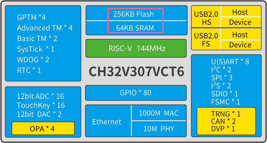
Chitu V307 (CH32V307) is a RISC-V core MCU, which is equipped with qinheng self-developed RISC-V core highland barley V4F, with a maximum dominant frequency of 144MHz and supports single precision floating-point operation (FPU). Generally, the size of Flash is 256 KB and the size of SRAM is 64 KB.
After carefully reading the application manual, it is found that the size of Flash and SRAM supports configuration. The specific configuration items are as follows:
- 192 KB Flash + 128 KB SRAM
- 224 KB Flash + 96 KB SRAM
- 256 KB Flash + 54 KB SRAM
- 288 KB Flash + 32 KB SRAM
Egg 1
The maximum RAM can be configured to 128 KB, which can be doubled directly. You can roll up your sleeves and tap the code. You don't have to worry about insufficient ram anymore~
In fact, there is A 320 KB SRAM in Chitu V307, which is divided into A and B blocks. The size of A and B blocks is determined by the SRAM of user_ CODE_ The mode bit determines that block A is responsible for storing the user code, and block B is reserved as the real SRAM of the single chip microcomputer. Each time it is powered on for operation, the user code with the size of block A is automatically loaded from the Code Flash.
Of course, the actual Flash and SRAM size of the user code should not exceed the configured range, otherwise the program will not run.

When actually operating Flash, there will be no problem of Flash waiting.
Egg 2
Careful friends may find that the maximum configuration of V307 Flash is 288 KB, while the size of Code Flash is 488 KB, which is also a hidden colored egg. The remaining 200 KB Flash can be used as storage, but we need to pay attention to the problem of Flash waiting there.
Configuration method
Since the Flash and SRAM of Chitu V307 are configurable, let's talk about the configuration method!
(1) WCHISBTool configuration
- step 1: switch the startup mode, BOOT0 = 1, BOOT1 = 0
- step 2: configure user selection word through WCHISPTool tool. See the following figure for specific steps
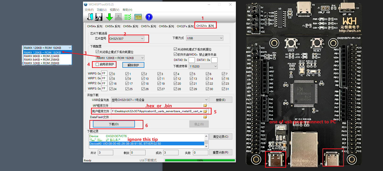
- step 3: switch the startup mode, BOOT0 = 0, BOOT1 = 0
(2) User code configuration
typedef enum
{
FlASH_192_SRAM_128 = 0,
FLASH_224_SRAM_96,
FLASH_256_SRAM_64,
FLASH_288_RAM_32
} FLASH_SRAM_DEFIN;
//note: this operation will take effect after reset
void Config_Flash_SRAM(FLASH_SRAM_DEFIN SetFlashSRAM)
{
uint8_t UserByte = FLASH_GetUserOptionByte() & 0xff; //get user option byte
switch(SetFlashSRAM)
{
case 0:
UserByte &= ~(0xc0); // SRAM_CODE_MODE = 00
break;
case 1:
UserByte &= ~(0xc0); // SRAM_CODE_MODE = 00
UserByte |= 0x7f; // SRAM_CODE_MODE = 01
break;
case 2:
UserByte &= ~(0xc0); // SRAM_CODE_MODE = 00
UserByte |= 0xbf; // SRAM_CODE_MODE = 10
break;
case 3:
UserByte |= 0xff; // SRAM_CODE_MODE = 11
break;
default:
break;
}
FLASH_Unlock();
FLASH_ProgramOptionByteData(0x1ffff802, UserByte);
FLASH_Lock();
}
/*********************************************************************
* @fn main
*
* @brief Main program.
*
* @return none
*/
int main(void)
{
NVIC_PriorityGroupConfig(NVIC_PriorityGroup_2);
Delay_Init();
USART_Printf_Init(115200);
printf("SystemClk:%d\r\n", SystemCoreClock);
Config_Flash_SRAM(FLASH_288_RAM_32); //The configuration Flash is 288kb and the SRAM is 32KB, which takes effect after reset
printf("userByte = %02x \r\n",FLASH_GetUserOptionByte() & 0xff);
while(1)
{
;
}
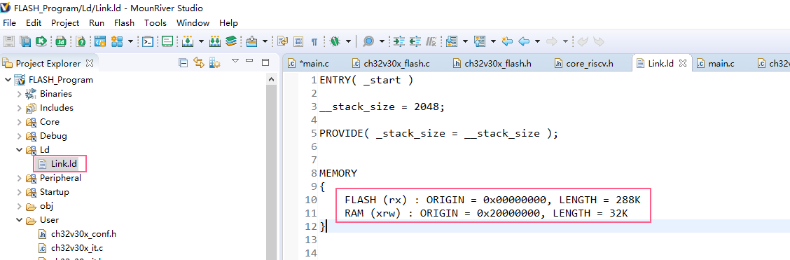
}Note that after the above two configuration methods are completed, it is also necessary to synchronize the uppercase of Flash and SRAM in the ld link file of the user's engineering code, which is consistent with the size of the user's choice word configuration. If you need to know about RISC-V MCU ld link file, you can view this post: RISC-V MCU ld link script description