Tip: after the article is written, the directory can be generated automatically. Please refer to the help document on the right for how to generate it
preface
This paper is a summary of the official smart home DIY project of learning RT thread. It is developed based on RT thread studio, using stm32f103 as the node to send data and stm32f407 as the gateway to upload data. (only one node is made here)
Tip: the following is the main content of this article. The following cases can be used for reference
1, Node sending data
1. Obtain the temperature with ds18b20
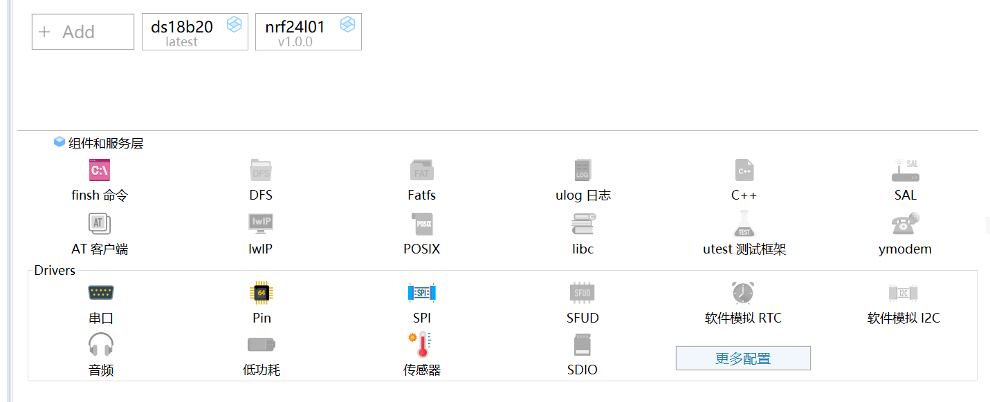
1. 1 add ds18b20 software package. Its configuration is as follows. The example code can not be enabled

After the software package is added, the Sensor will be automatically checked, as shown in the figure below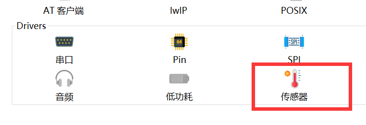
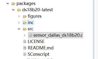
1.2 read the ds18b20 source code to understand the sensor framework
In the following figure, open the sensor_dallas_ds18b20.c Documents
The function of Sensor equipment is to provide a unified operation interface for the upper layer and improve the reusability of the upper layer code.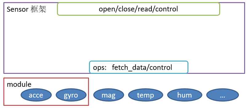
It provides the upper layer with a standard device interface open/close/read/write/control, and the lower layer with a simple ops interface: fetch_data/control. And the framework supports modules to provide services for coupled sensor devices at the bottom.
The following only explains the underlying driver ops(operations: operation command) interface
ops (operation function) contains two function pointers. One is used to obtain sensor data and the other is used to control the sensor through control commands. It is defined as follows
struct rt_sensor_ops
{
    rt_size_t (*fetch_data)(struct rt_sensor_device *sensor, void *buf, rt_size_t len);
    rt_err_t (*control)(struct rt_sensor_device *sensor, int cmd, void *arg);
};
ops is actually a structure used to store interface functions. Its specific application in this example is as follows
static struct rt_sensor_ops sensor_ops =
{
    ds18b20_fetch_data,
    ds18b20_control
};
ds18b20_ fetch_ The data function is defined as follows:
/**
  * @brief  sensor The fetch_data() function of the ops interface definition (structure) member in the framework is to obtain sensor data
  * @param  sensor Supports three modes: interrupt, polling and FIFO. Here, ds18b20 is read by polling
  * @retval Return temperature data or 0
  */
static rt_size_t ds18b20_fetch_data(struct rt_sensor_device *sensor, void *buf, rt_size_t len)
{
    RT_ASSERT(buf);

    if (sensor->config.mode == RT_SENSOR_MODE_POLLING)
    {
        return _ds18b20_polling_get_data(sensor, buf);
    }
    else
        return 0;
}
ds18b20_ The control function is defined as follows
/**
  * @brief  sensor The definition (structure) of the ops interface in the framework, and the control() function of the member is to control the sensor through the control command
  * @param  Because ds18b20 does not support control
  * @retval So return directly to RT_EOK
  */
static rt_err_t ds18b20_control(struct rt_sensor_device *sensor, int cmd, void *args)
{
    rt_err_t result = RT_EOK;

    return result;
}
With the above ops interface, you also need to register a sensor device (any device needs to be registered before it can be used), so that the upper layer can find the sensor device and control it. The sensor device registration is as follows:
/**
  * @brief Sensor device registration
    * After completing the docking of sensor ops, a sensor device must be registered so that the upper layer can find the sensor device and control it
  * @param rt_hw_ds18b20_init()
  * @retval RT_EOK or -RT_ERROR
  */
int rt_hw_ds18b20_init(const char *name, struct rt_sensor_config *cfg)
{
    rt_int8_t result;
    rt_sensor_t sensor_temp = RT_NULL;  /* Defines the structure pointer of a sensor */

    if (!ds18b20_init((rt_base_t)cfg->intf.user_data)) /* ds18b20 If hardware initialization is successful, 0 is returned */
    {
        /* Allocate memory for structure */
        sensor_temp = rt_calloc(1, sizeof(struct rt_sensor_device));
        if (sensor_temp == RT_NULL)
            return -1;
/* sensor Configuration of relevant parameters before initialization */
        sensor_temp->info.type       = RT_SENSOR_CLASS_TEMP;
        sensor_temp->info.vendor     = RT_SENSOR_VENDOR_DALLAS;
        sensor_temp->info.model      = "ds18b20";
        sensor_temp->info.unit       = RT_SENSOR_UNIT_DCELSIUS;
        sensor_temp->info.intf_type  = RT_SENSOR_INTF_ONEWIRE;
        sensor_temp->info.range_max  = SENSOR_TEMP_RANGE_MAX;
        sensor_temp->info.range_min  = SENSOR_TEMP_RANGE_MIN;
        sensor_temp->info.period_min = 5;

        rt_memcpy(&sensor_temp->config, cfg, sizeof(struct rt_sensor_config));
        sensor_temp->ops = &sensor_ops;
/* Register sensor devices */
        result = rt_hw_sensor_register(sensor_temp, name, RT_DEVICE_FLAG_RDONLY, RT_NULL);
        if (result != RT_EOK)
        {
            LOG_E("device register err code: %d", result);
            goto __exit;
        }

    }
    else
    {
        LOG_E("DS18B20 init failed! Please check the connection!");
        goto __exit;
    }

    return RT_EOK;

__exit:
    if (sensor_temp)
        rt_free(sensor_temp);
    return -RT_ERROR;
}
Call RT_ hw_ ds18b20_ The init() function completes the hardware initialization and registers the device.
These are the operations used by the ops underlying driver.
1.3 create thread read temperature
Note: you have to call RT first_ hw_ ds18b20_ The init() function completes initialization. The specific implementation is as follows:
/* ds18b20 initialization */
static int rt_hw_ds18b20_port(void)
{
    struct rt_sensor_config cfg;

    cfg.intf.user_data = (void *)DS18B20_DATA_PIN;  /* Store data pins in the structure */
    rt_hw_ds18b20_init("ds18b20", &cfg);            /* initialization */

    return RT_EOK;
}
INIT_COMPONENT_EXPORT(rt_hw_ds18b20_port);
Thread creation is as follows:
ds18b20_thread = rt_thread_create("18b20tem", read_temp_entry, "temp_ds18b20",
                                  640, RT_THREAD_PRIORITY_MAX / 2, 20);
if (ds18b20_thread != RT_NULL)
{
    rt_thread_startup(ds18b20_thread);
}
"temp_ds18b20" is the parameter in the thread entry function, which is used to find the device.
The thread entry function is as follows:
/* Thread entry function: get temperature data from sensor and send it to another thread through mailbox */
static  void  read_temp_entry(void *parameter)
{
    struct  tmp_msg   msg;           /* Declare a structure for storing temperature and time stamps */
    rt_device_t  dev = RT_NULL;
    rt_size_t   res;

    dev = rt_device_find(parameter);    /* Find the device. If it fails, return to exit*/
    if(dev == RT_NULL)
    {
        rt_kprintf("can't find device:%s\n",parameter);
        return;
    }
    /* Open the device, and return if it fails */
    if (rt_device_open(dev, RT_DEVICE_FLAG_RDWR)!=RT_EOK)
    {
        rt_kprintf("open device failed!\n");
        return;
    }
    rt_device_control(dev, RT_SENSOR_CTRL_SET_ODR, (void *)100);    /*Set output frequency: 100Hz */

    while(1)
    {
        res = rt_device_read(dev, 0, &sensor_data, 1);  /* Read 1 byte of data from sensor */
        if (res!=1)
        {
            rt_kprintf("read data failed! size is %d\n",res);
            rt_device_close(dev);
            return;
        }
        else
        {
            /* Apply for a memory block. If the memory pool is full, suspend the thread and wait */
     //       msg = rt_mp_alloc(tmp_msg_mp, RT_WAITING_FOREVER);
            msg.timestamp = sensor_data.timestamp;  /* Get timestamp*/
            msg.int_value = sensor_data.data.temp;  /* Get temperature */
   //         rt_mb_send(tmp_msg_mb, (rt_ubase_t)msg); /* Send mail*/
            rt_mq_send(tmp_msg_mq, &msg, sizeof msg); /* Send message queue */
          //  msg = NULL;
        }
        rt_thread_mdelay(500);      /* The delay function is mainly used to block the thread so that it can be scheduled*/

    }
}
2. Send data with nrf24l01
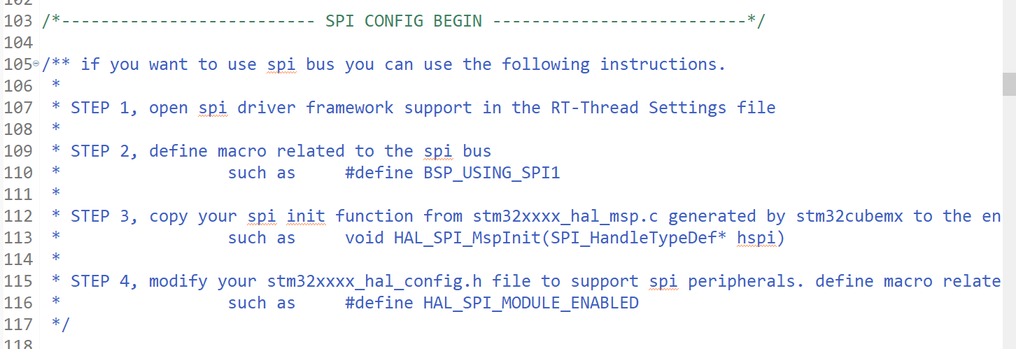
2.1 add nrf software package and start corresponding equipment (SPI is used)
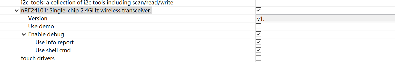
Note: for the nrf24l01 package here, select v1 Version 0.0
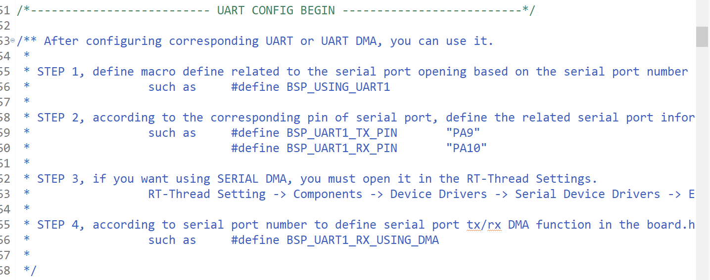
According to board The SPI CONFIG part of H prompts and carries out corresponding operations
The above only registers spi bus devices. In addition, spi slave devices need to be registered and mounted on the bus. The specific implementation is as follows:
static int rt_hw_nrf24l01_init(void)
{
    __HAL_RCC_GPIOG_CLK_ENABLE();
    rt_hw_spi_device_attach("spi2", "spi20", GPIOG, GPIO_PIN_7);

    return RT_EOK;
}
INIT_COMPONENT_EXPORT(rt_hw_nrf24l01_init);
2.2 creating nrf24l01 threads
Create thread:
nrf24l01_thread  = rt_thread_create("nrfsend", nrf24l01_send_entry, RT_NULL,
                                        1024, RT_THREAD_PRIORITY_MAX / 2, 20);
    if (nrf24l01_thread != RT_NULL)
    {
        rt_thread_startup(nrf24l01_thread);
    }
Thread entry function: this completes the initialization of nrf24l01 and sending data (to another nrf24l01, the so-called gateway)
static  void nrf24l01_send_entry(void *parameter)
{
    struct  tmp_msg  msg;
    struct  hal_nrf24l01_port_cfg   halcfg;
    nrf24_cfg_t cfg;
    uint8_t rbuf[32+1] = {0};
    uint8_t tbuf[32]= {0};


    nrf24_default_param(&cfg);
    halcfg.ce_pin = NRF24L01_CE_PIN;
    halcfg.spi_device_name = NRF24L01_SPI_DEVICE;
    cfg.role = ROLE_PTX;    //Indicates the sending mode
//  cfg.role = ROLE_PRX;    Because I used this at the beginning, the problem is that it can only be sent once, and then the fish component can't be used

    cfg.ud = &halcfg;
    cfg.use_irq = 0;
    nrf24_init(&cfg);

    while(1)
    {
        rt_thread_mdelay(500);

        if (rt_mq_recv(tmp_msg_mq, &msg, sizeof msg, RT_WAITING_FOREVER) == RT_EOK)
        {
            if (msg.int_value >=0)
            {
                /* Store data in tbuf */
                rt_sprintf((char *)tbuf, "%d,+%3d.%d",msg.timestamp,msg.int_value / 10,msg.int_value % 10);
            }
            else
            {
                rt_sprintf((char *)tbuf, "%d,-%2d.%d",msg.timestamp,msg.int_value / 10,msg.int_value % 10);
            }

            rt_kputs((char *)tbuf);
            rt_kputs("\n");
     //       rt_mp_free(msg); /*  Free memory*/
       //     msg = RT_NULL;   /*  Please do as necessary*/
        }
        if (nrf24_ptx_run(rbuf, tbuf, rt_strlen((char *)tbuf))<0)
        {
            rt_kputs("Send failed! >>> ");
        }

    }
}
The above is all the contents of the node, Source download
Extraction code: imad
2, The gateway receives data and uploads it to ONENET
2.1 nrf24l01 node receiving data
2.1. 1 create nrf24l01 thread, which is used to receive data and save it to ringbuffer to send events
  nrf24l01_thread  = rt_thread_create("nrfrecv", nrf24l01_receive_entry, RT_NULL,
                                        2048, RT_THREAD_PRIORITY_MAX / 2, 20);
    if (nrf24l01_thread != RT_NULL)
    {
        rt_thread_startup(nrf24l01_thread);
    }
2.1. 2 thread entry function
static void nrf24l01_receive_entry(void *parameter)
{
    struct  recvdata    buf;
    struct  recvdata    *buf_mp;
    static  char  str_data_p0[64];
    struct hal_nrf24l01_port_cfg halcfg;
    nrf24_cfg_t cfg;

    nrf24_default_param(&cfg);    // Configure defaults first
    halcfg.ce_pin = NRF24L01_CE_PIN;
    halcfg.spi_device_name = NRF24L01_SPI_DEVICE;
    cfg.role = ROLE_PRX;  //Role: receiving data
    cfg.ud = &halcfg;     // Used to transfer the underlying configuration
    cfg.use_irq = 0;      // Use interrupt
    nrf24_init(&cfg);    // initialization

    while (1)
    {
        if (!rx_pipe_num_choose())
        {
            /* Parse the received data through sscanf */
            if (sscanf((char *)RxBuf_P0,"%d,+%f",&buf.timestamp_p0,&buf.temperature_p0)!=2)
            {
                /* Parse the received data through sscanf */
                if (sscanf((char *)RxBuf_P0,"%d,-%f",&buf.timestamp_p0,&buf.temperature_p0)!=2)
                {
                   buf.temperature_p0 = 0;
                   buf.timestamp_p0 = 0;
                }
                buf.temperature_p0 = -buf.temperature_p0;
            }
            if (0!=buf.temperature_p0)
            {
                sprintf(str_data_p0, "%d,%f\n", buf.timestamp_p0, buf.temperature_p0);
                /* Store data in ringbuffer */
                rt_ringbuffer_put(recvdatabuf_p0, (rt_uint8_t *)str_data_p0, strlen(str_data_p0));
                /* The event is sent only after the data is received and stored in the ringbuffer */
                rt_event_send(recvdata_event, WRITE_EVENT_P0);
            }
            /* Apply for a piece of memory. If the memory pool is full, suspend waiting */
           buf_mp =rt_mp_alloc(tmp_msg_mp, RT_WAITING_FOREVER);
           buf_mp->temperature_p0 = buf.temperature_p0;
           buf_mp->timestamp_p0 = buf.timestamp_p0;
           rt_mb_send(tmp_msg_mb, (rt_ubase_t)buf_mp);
           buf_mp =NULL;
        }
        rt_thread_mdelay(500);
    }
}
2.2 write data to sd card
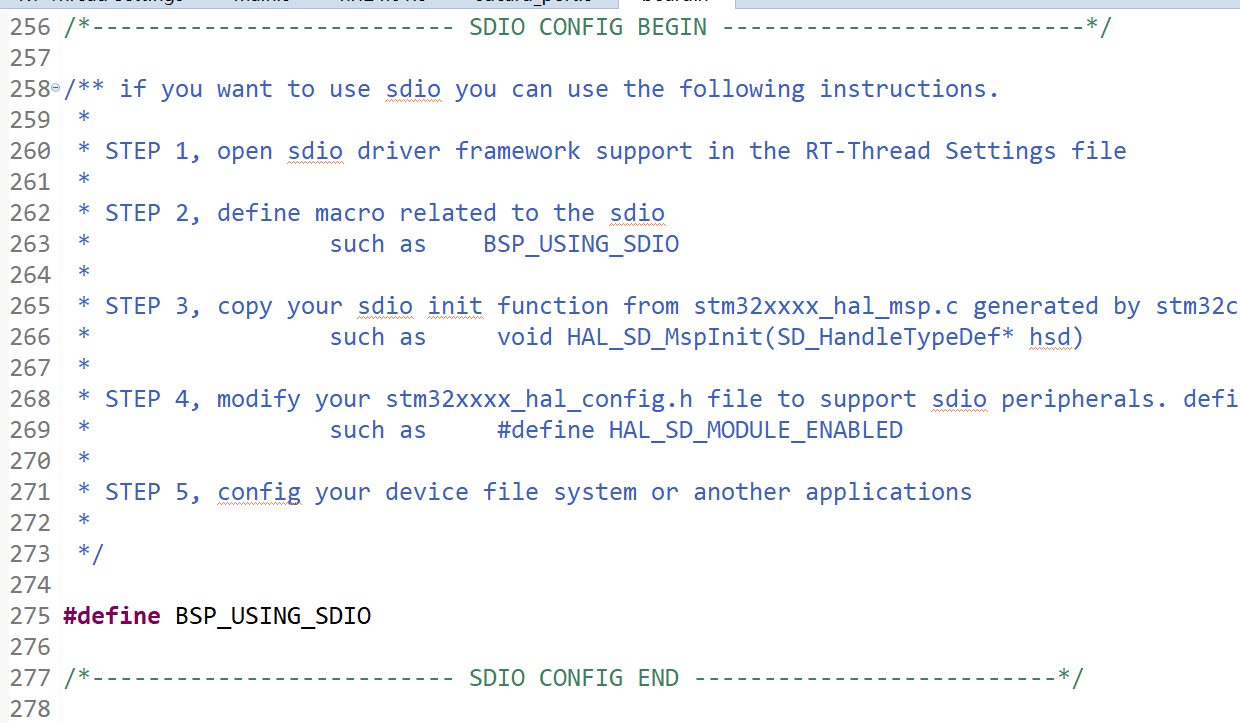
2.2. 1 add SDIO, DFS, Fatfs, Libc, POSIX
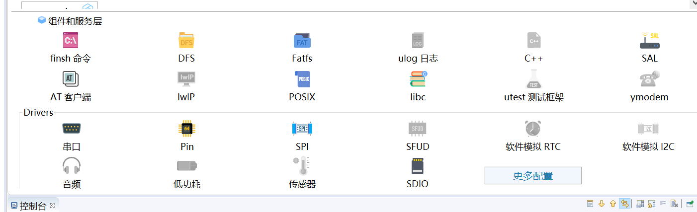
Configure sdio according to the following figure
After completing the above configuration, you can see that the "sd0" device exists
2.2. 2 mount the file system on the DFS of RT thread
Create thread:
int stm32_sdcard_mount(void)
{
    rt_thread_t tid;    /* Define thread handle */
    /* Create thread */
    tid = rt_thread_create("sd_mount", sd_mount, RT_NULL, 2048, RT_THREAD_PRIORITY_MAX - 2, 20);
    if (tid!=RT_NULL)
    {
        rt_thread_startup(tid);
    }
    else
    {
        LOG_E("create sd_mount thread err!");
    }
    return RT_EOK;
}
INIT_APP_EXPORT(stm32_sdcard_mount);
Thread entry function:
/* Thread entry function: sd card waiting for initialization  */
void  sd_mount(void *parameter)
{
    while(1)
    {
        rt_thread_mdelay(500);
        if (rt_device_find("sd0")!=RT_NULL)
        {
            if (dfs_mount("sd0", "/", "elm", 0, 0)==RT_EOK)
            {
                LOG_I("sd card mount to '/'");
                break;
            }
            else
            {
                LOG_W("sd card mount to '/' failed!");
            }
        }
    }
}
2.2. 3. Receive events and write data to sd card
Create thread:
DFS_thread_p0 = rt_thread_create("DFSsaveP0", save_recv_data_entry, RT_NULL,
                                2048, RT_THREAD_PRIORITY_MAX / 2 - 1, 20);
  if (DFS_thread_p0 != RT_NULL)
  {
      rt_thread_startup(DFS_thread_p0);
  }
Thread entry function:
static  void  save_recv_data_entry(void *parameter)
{
//    FILE  *recvdatafile_p0 =RT_NULL;
    rt_uint32_t     set;
    static  int  writebuffer[1024];
    rt_size_t   size;
    while(1)
    {
        /* Receive events of interest WRIE_EVENT, which is received in a permanent waiting mode */
        if (rt_event_recv(recvdata_event, WRITE_EVENT_P0, RT_EVENT_FLAG_OR | RT_EVENT_FLAG_CLEAR, RT_WAITING_FOREVER, &set)!=RT_EOK)
        {
            continue;
        }

            /* Receive events of interest WRIE_EVENT is received in a 1000ms timeout mode */
            if (rt_event_recv(recvdata_event, WRITE_EVENT_P0, RT_EVENT_FLAG_OR | RT_EVENT_FLAG_CLEAR, rt_tick_from_millisecond(1000), &set)==RT_EOK)
            {
                /* Judge whether the written data size does not reach the set threshold of ringbuffer*/
                if (rt_ringbuffer_data_len(recvdatabuf_p0) > THRESHOLD)
                {
                    /* Write data directly at the threshold */
                    recvdatafile_p0 = fopen("recvdata_p0.csv", "ab+");
                    if (recvdatafile_p0!=RT_NULL)
                    {
                        while(rt_ringbuffer_data_len(recvdatabuf_p0))
                        {
                            size = rt_ringbuffer_get(recvdatabuf_p0, (rt_uint8_t *)writebuffer, THRESHOLD);
                            fwrite(writebuffer, 1,size,recvdatafile_p0);
                        }
                        fclose(recvdatafile_p0);
                    }
                }
                /* Continue to receive interested event write before the threshold is reached_ Event, received in 1000ms timeout mode */
                continue;
            }
            /* 100ms When you arrive, you haven't received the event of interest. At this time, whether it reaches the threshold or not, you can write it directly  */
            recvdatafile_p0 = fopen("recvdata_p0.csv", "ab+");
            if (recvdatafile_p0 !=RT_NULL)
            {
                while(rt_ringbuffer_data_len(recvdatabuf_p0))
                {
                    size = rt_ringbuffer_get(recvdatabuf_p0, (rt_uint8_t *)writebuffer, THRESHOLD);
                    fwrite(writebuffer, 1, size, recvdatafile_p0);
                }
                fclose(recvdatafile_p0);
            }
    }

}
Set a fixed time for timing. If the time is up and the data has not been written to the threshold value of the ringbuffer, no matter whether the data reaches the threshold value or not, directly write all the data in the ringbuffer to the file. To realize this idea, it needs to be used with event set
2.3 uploading data to ONENET
2.3. 1 enable AT and esp8266, and configure relevant parameters in ONENET software package
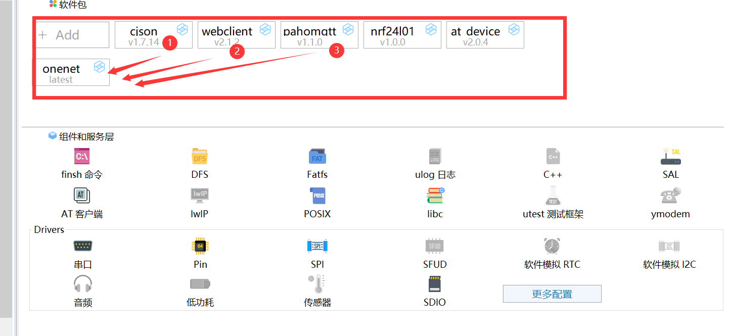
As shown in the figure above, after adding onenet package, another three packages will be added automatically.
In addition, you need to fill in the relevant information of esp8266, as shown in the figure below:
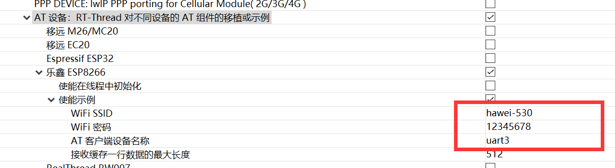
esp8266 is connected through serial port, so remember to configure serial port
2.3.2 MQTT initialization
The upload of OneNet package data and the reception of commands are based on MQTT. The initialization of OneNet is actually the initialization of MQTT client. The OneNet package provides an interface to onenet_mqtt_init allows the user to initialize MQTT. Subsequent operations, such as uploading data to OneNet server, can only be performed after MQTT is successfully initialized.
static  void  onenet_mqtt_init_entry(void *parameter)
{
    uint8_t onenet_mqtt_init_failed_times;

    /* mqtt initialization */
    while(1)
    {
        if (!onenet_mqtt_init())
        {
            /* mqtt After successful initialization, release the signal to inform onenet_ upload_ data_ The thread thread can upload data */
            rt_sem_release(mqttinit_sem);
            return;
        }
        rt_thread_mdelay(100);
        LOG_E("onenet mqtt init failed %d times",onenet_mqtt_init_failed_times++);
    }
}
2.3. 3 upload data to ONENET
On the premise that ESP8266 is normally connected to WIFI, after MQTT initialization is successful, you can safely and boldly upload data to OneNet.
static  void  onenet_upload_data_entry(void *parameter)
{
    struct  recvdata  *buf_mp;

    /* The semaphore is received in the permanent wait mode. If it is not received, the thread will hang all the time */
    rt_sem_take(mqttinit_sem, RT_WAITING_FOREVER);
    /*This semaphore is not used later. Delete it and recycle resources*/
    rt_sem_delete(mqttinit_sem);
    while(1)
    {
        /* 500ms Upload data once */
        rt_thread_delay(rt_tick_from_millisecond(500));
        if (rt_mb_recv(tmp_msg_mb, (rt_ubase_t*)&buf_mp,RT_WAITING_FOREVER)==RT_EOK)
        {
            /* Upload the data of sending node 1 to OneNet server, and the data stream name is temperature_p0 */
            if(onenet_mqtt_upload_digit("temperature_p0", buf_mp->temperature_p0)!=RT_EOK)
            {
                rt_kprintf("upload temperature_p0 has an error,try again\n");
            }
            else
            {
                rt_kprintf("onenet upload ok >>> temp_p0:%f\n",buf_mp->temperature_p0);
            }
            rt_kputs("\n\n");
            rt_mp_free(buf_mp);     /* Free memory block */
            buf_mp = RT_NULL;       /* Please do as necessary */
        }
    }
}
END