1, Introduction
Digital signals are generated by sampling, quantizing and encoding continuously changing analog signals, which is called PCM (Pulse Code Modulation), that is, Pulse Code Modulation.
Pulse code modulation is to transform a time continuous analog signal into a time discrete digital signal, which is transmitted in the channel. Pulse code modulation is the process of sampling analog signals first, then quantizing the sample amplitude and coding.
Sampling is to scan the analog signal periodically and turn the time continuous signal into time discrete signal. After sampling, the analog signal shall also contain all the information in the original signal, that is, it can recover the original analog signal without distortion. The lower limit of its sampling rate is determined by the sampling theorem. The sampling rate is 8Kbit/s.
Quantization is to discretize the amplitude of the sampled instantaneous value, that is, use a set of specified levels to represent the instantaneous sampling value with the closest level value.
After sampling and quantizing an analog signal, the quantized pulse amplitude modulation signal is obtained, which is only a limited number of values.
Coding is to use a group of binary codes to represent each quantization value with a fixed level. However, in fact, quantization is completed simultaneously in the coding process, so the coding process is also called analog-to-digital transformation, which can be recorded as A/D.
The voice signal is first pulse sampled through an anti aliasing low-pass filter, Become a sampling signal with 8KHz repetition frequency (i.e. discrete pulse amplitude modulation PAM signal), and then "round" the PCM signal with continuous amplitude The method quantizes the signals with limited amplitude values, and then converts them into binary codes after coding. For telephone, CCITT specifies that the sampling rate is 8KHz, and 8 bits are coded for each sampling value, that is, there are 2 ^ 8 = 256 quantization values, so the standard digital rate after PCM coding for each session is 64kb/s. In order to solve the problems of large quantization error and poor sound quality of small signal in uniform quantization, the non-linear quantization method of uneven selection of quantization interval is adopted in practice, that is, the quantization characteristics are dense in small signal time division and small quantization interval, while sparse in large signal time division and large quantization interval
The signal - to - noise ratio of uniformly quantized small signal is small
Non uniform quantization: since the probability of occurrence of small amplitude signal is greater than that of large amplitude signal for some source signals, such as speech signal, the effect of non-uniform quantization (i.e. the quantization step of small amplitude signal is less than that of large amplitude signal) is better (manifested in speech signal, which can make the signal have sufficient signal-to-noise ratio)
The characteristic of non-uniform quantization is that the signal is amplified by small signal amplitude and compressed by large signal amplitude through a nonlinear device, and then realized by uniform quantization
2, Source code
function varargout = PCM(varargin)
% PCM M-file for PCM.fig
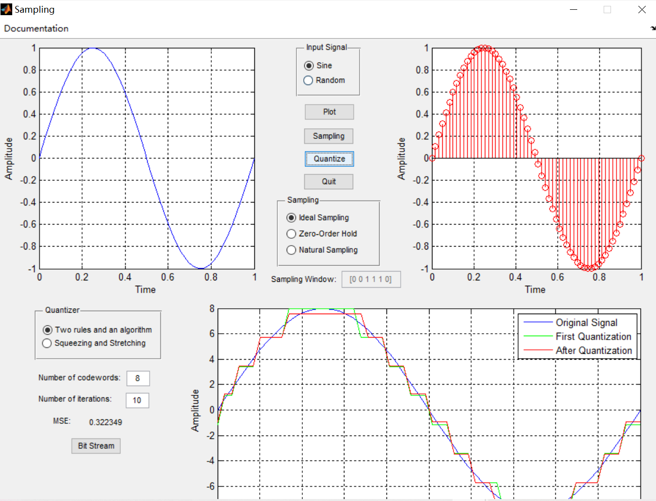
%      PCM was designed in order to show how PCM works
%
%      To simplify the undesrtanding of this method, the program first takes
%      a sine wave. Then you can choose a sampling scheme, and you can see
%      the output of the sampler. You can choose one out of three sampling
%      methods.
%      If you choose natural sampling; then you will have the chance to modify
%      the sampling window, and see the effects of this change in the output of
%      the sampler.
%
%      Once you got the sampled signal you can quantize it by a method that is
%      known as two rules and an alorithm.
%      The option Squeezing and Stretching shows the best G(x) tha minimizes
%      the MSE. You can better understand this using the book
%      Telecommunications Demystified written by Carl Nassar. You can find
%      information about this on Chapter four of that book.
%      You can edit the bit's number and the number of iterations of the
%      algorithm. The bigger the number of bits, the smaller the MSE.
%      The picture shows the signal after quantization, the first iteration
%      in the quantization process and the output of the quantizer
%
%      Then, by pressing the Bit Stream button you will see the PCM output
%      of the signal that you have selected in the input area.
%
%      Everytime you change something, you must push the button that is
%      related with the change you have just made. For example if don't
%      want to work anymore with the sine wave and you choose the random
%      signal, then you have to push the plot button in order to see the
%      plot of the random signal, and if you change of sampling method you
%      have to push the sampling button, when you changhe the sampling
%      window. So if you change the number of codewords or the number of
%      the iterations you will have to press the quantize button again.

% Edit the above text to modify the response to help PCM

% Last Modified by GUIDE v2.5 14-Mar-2007 12:32:35

% Begin initialization code - DO NOT EDIT
gui_Singleton = 1;
gui_State = struct('gui_Name',       mfilename, ...
                   'gui_Singleton',  gui_Singleton, ...
                   'gui_OpeningFcn', @PCM_OpeningFcn, ...
                   'gui_OutputFcn',  @PCM_OutputFcn, ...
                   'gui_LayoutFcn',  [] , ...
                   'gui_Callback',   []);
if nargin && ischar(varargin{1})
    gui_State.gui_Callback = str2func(varargin{1});
end

if nargout
    [varargout{1:nargout}] = gui_mainfcn(gui_State, varargin{:});
else
    gui_mainfcn(gui_State, varargin{:});
end
% End initialization code - DO NOT EDIT


% --- Executes just before PCM is made visible.
function PCM_OpeningFcn(hObject, eventdata, handles, varargin)
% This function has no output args, see OutputFcn.
% hObject    handle to figure
% eventdata  reserved - to be defined in a future version of MATLAB
% handles    structure with handles and user data (see GUIDATA)
% varargin   command line arguments to PCM (see VARARGIN)

% Choose default command line output for PCM
handles.output = hObject;

% Update handles structure
guidata(hObject, handles);

% UIWAIT makes PCM wait for user response (see UIRESUME)
% uiwait(handles.figure1);


% --- Outputs from this function are returned to the command line.
function varargout = PCM_OutputFcn(hObject, eventdata, handles)
% varargout  cell array for returning output args (see VARARGOUT);
% hObject    handle to figure
% eventdata  reserved - to be defined in a future version of MATLAB
% handles    structure with handles and user data (see GUIDATA)

% Get default command line output from handles structure
varargout{1} = handles.output;


% --- Executes on button press in pushbutton2.
function pushbutton2_Callback(hObject, eventdata, handles)
% hObject    handle to pushbutton2 (see GCBO)
% eventdata  reserved - to be defined in a future version of MATLAB
% handles    structure with handles and user data (see GUIDATA)
if (get(handles.radiobutton2,'Value') == get(handles.radiobutton2,'Max')) % Verifies if Sine wave was selected
    t=linspace(0,1,60); % Creates the time variable from 0 to 1 with a length of 60 or 60 points
    y=sin(2*pi*t); % Creates a sine wave of frequency 1 with the t vector
    axes(handles.axesanalog) % Select the proper axes
    plot(t,y);
    xlabel('Time');
    ylabel('Amplitude');
    grid on;
elseif (get(handles.radiobutton3,'Value') == get(handles.radiobutton3,'Max')) % Verifies if Random signal was selected
    t=linspace(0,60,60); % Creates the time variable from 0 to 60 with a length of 60 or 60 points
    y=rand([1 60]); % Creates a random signal of length 60 or with 60 points
    axes(handles.axesanalog) % Select the proper axes
    plot(t,y);
    xlabel('Time');
    ylabel('Amplitude');
    grid on;
end
handles.amp=y; % Saves the input signal y in the amp variable at the handles structure
handles.time=t; % Saves the input signal t in the time variable at the handles structure
guidata(gcbo,handles); % Save the changes made to the handles structure

% --- Executes on button press in pushbutton3.
function pushbutton3_Callback(hObject, eventdata, handles)
% hObject    handle to pushbutton3 (see GCBO)
% eventdata  reserved - to be defined in a future version of MATLAB
% handles    structure with handles and user data (see GUIDATA)
close; % Close the application

% --- Executes on button press in pushbutton4.
function pushbutton4_Callback(hObject, eventdata, handles)
% hObject    handle to pushbutton4 (see GCBO)
% eventdata  reserved - to be defined in a future version of MATLAB
% handles    structure with handles and user data (see GUIDATA)
if (get(handles.radiobutton4,'Value') == get(handles.radiobutton4,'Max'))
    t=handles.time; % recover the saved variable t from the handles structure
    y=handles.amp; % recover the saved variable y from the handles structure
    p=ones(1, length(t)); % creates a vector containing only ones
    outideal=p.*y; % Multiplies the two vectors to get the output of an ideal sampler
    axes(handles.axessampled) % Select the proper axes
    stem(t,outideal,'ro');
    xlabel('Time');
    ylabel('Amplitude');
    grid on;
    handles.signal=outideal;
    guidata(gcbo,handles);
elseif (get(handles.radiobutton5,'Value') == get(handles.radiobutton5,'Max'))
    t=handles.time; % recover the saved variable t from the handles structure
    y=handles.amp; % recover the saved variable y from the handles structure
    p=ones(1, length(t)); % creates a vector containing only ones
    outhold=p.*y; % Multiplies the two vectors to get the output of an ideal sampler
    axes(handles.axessampled) % Select the proper axes
    stairs(t,outhold,'r'); %Plot the signal in a stairs shape making it looks like a zero order hold sampler
    xlabel('Time');
    ylabel('Amplitude');
    grid on;
    handles.signal=outhold;
    guidata(gcbo,handles);
elseif (get(handles.radiobutton6,'Value') == get(handles.radiobutton6,'Max'))
    t=handles.time; % recover the saved variable t from the handles structure
    y=handles.amp; % recover the saved variable y from the handles structure
    test1=eval(get(handles.edit1,'String')); % Evals the value that is contained in the Edit 1
    if isnan(test1) % Test if it is a number or not. If not it displays an error message
        errordlg('You must enter a numeric value','Bad Input','modal')
    end
    lenp=length(t)/length(test1); %Calculates the length of the vector so it can make it a periodic signal with the
    %right size so it can work properly
    p=ones(1, lenp); %  Creates a vector of only ones of lenght lenp
    per=test1'*p; % Creates a matrix, containing lenp times the vector test1
    per=per(:); % Concatenates the columns of the matrix so it becomes a vector
    outnormal=per'.*y; % Multiplies the two vectors to get the output of a normal sampler
    axes(handles.axessampled) % Select the proper axes
    plot(t,outnormal,'r');
    xlabel('Time');
    ylabel('Amplitude');
    grid on;
    handles.signal=outnormal;
    guidata(gcbo,handles);
end

function edit1_Callback(hObject, eventdata, handles)
% hObject    handle to edit1 (see GCBO)
% eventdata  reserved - to be defined in a future version of MATLAB
% handles    structure with handles and user data (see GUIDATA)

% Hints: get(hObject,'String') returns contents of edit1 as text
%        str2double(get(hObject,'String')) returns contents of edit1 as a double

% --- Executes during object creation, after setting all properties.
function edit1_CreateFcn(hObject, eventdata, handles)
% hObject    handle to edit1 (see GCBO)
% eventdata  reserved - to be defined in a future version of MATLAB
% handles    empty - handles not created until after all CreateFcns called

% Hint: edit controls usually have a white background on Windows.
%       See ISPC and COMPUTER.
if ispc && isequal(get(hObject,'BackgroundColor'), get(0,'defaultUicontrolBackgroundColor'))
    set(hObject,'BackgroundColor','white');
end

% --- Executes on button press in radiobutton6.
function radiobutton6_Callback(hObject, eventdata, handles)
% hObject    handle to radiobutton6 (see GCBO)
% eventdata  reserved - to be defined in a future version of MATLAB
% handles    structure with handles and user data (see GUIDATA)

% Hint: get(hObject,'Value') returns toggle state of radiobutton6
if (get(handles.radiobutton6,'Value') == get(handles.radiobutton6,'Max'))
    set(handles.edit1,'Enable', 'on'); % Enables the Edit1 object once this radiobutton is selected
end

% --- Executes on button press in radiobutton4.
function radiobutton4_Callback(hObject, eventdata, handles)
% hObject    handle to radiobutton4 (see GCBO)
% eventdata  reserved - to be defined in a future version of MATLAB
% handles    structure with handles and user data (see GUIDATA)

% Hint: get(hObject,'Value') returns toggle state of radiobutton4
if (get(handles.radiobutton6,'Value') == get(handles.radiobutton6,'Min'))
    set(handles.edit1,'Enable', 'off'); % Disables the Edit1 object once this radiobutton is selected
end

% --- Executes on button press in radiobutton5.
function radiobutton5_Callback(hObject, eventdata, handles)
% hObject    handle to radiobutton5 (see GCBO)
% eventdata  reserved - to be defined in a future version of MATLAB
% handles    structure with handles and user data (see GUIDATA)

% Hint: get(hObject,'Value') returns toggle state of radiobutton5
if (get(handles.radiobutton6,'Value') == get(handles.radiobutton6,'Min'))
    set(handles.edit1,'Enable', 'off'); % Disables the Edit1 object once this radiobutton is selected
end

```
3, Operation results

