Materials provided by small partners:
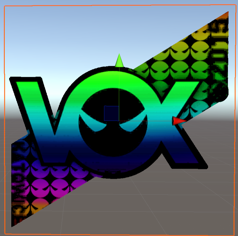
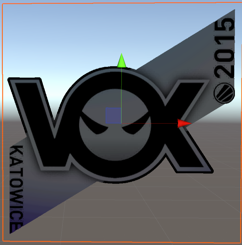
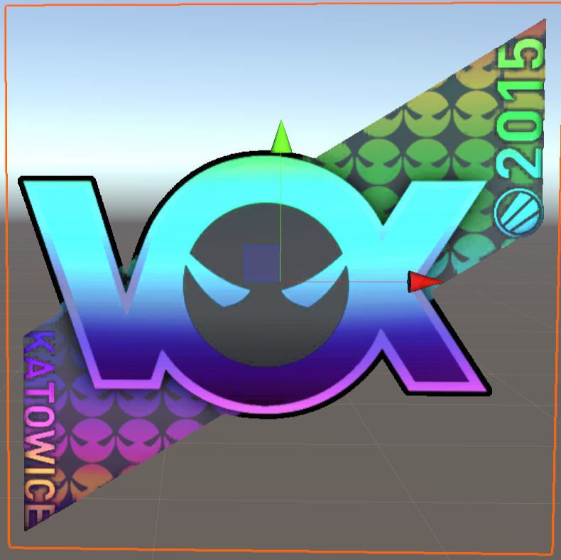
hologram sticker effect, referred to as holo:
achievements:
The implementation of shader graph based on URP and built in pipeline
1. Effect analysis
Here you can see the sticker effect of csgo: StatTrak™ AWP | Man-o'-war (Minimal Wear) | 3D Skin Viewer
According to the observation, it is found that:
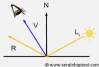
a. The holographic color changes according to the viewing angle, so the view direction dot normal direction (VdotN) will be used, that is, V and N in the figure below. Multiply two unit vector points to get the cos value of their included angle. The larger the value, the smaller the included angle (imagine the cos curve).
b. holography is a multi-layer superposition. The speed and color of each layer are different. So we will write the holographic effect into one function and then call it several times.
2. Realization
Based on Unity 2019.4.23
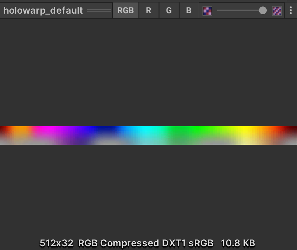
The general process is that we take the above figure as the color palette, VdotN as the abscissa, and the ordinate as a fixed value. As the viewing angle changes, the shader will sample the rainbow color from left to right horizontally in the figure. We use a small y value for the background part of the sticker and a high y value for the main body, so that the color of the background is gray and the color of the main body is very bright.

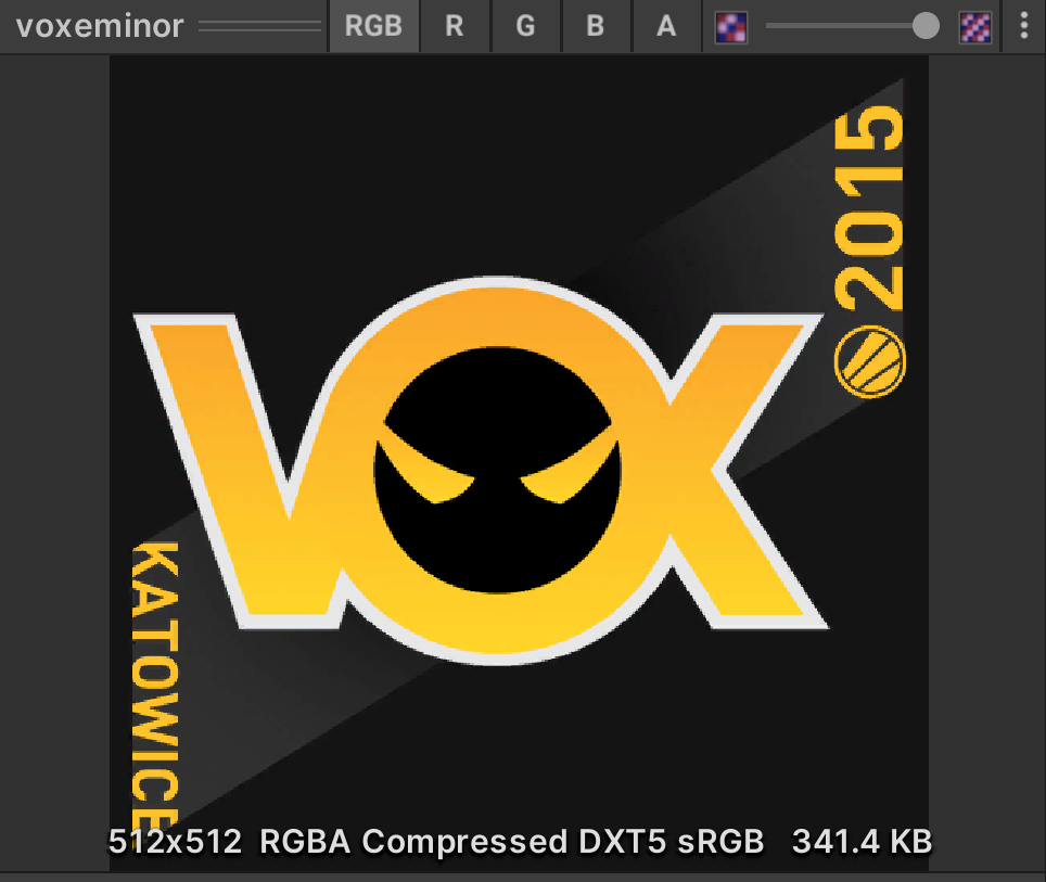
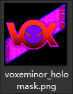
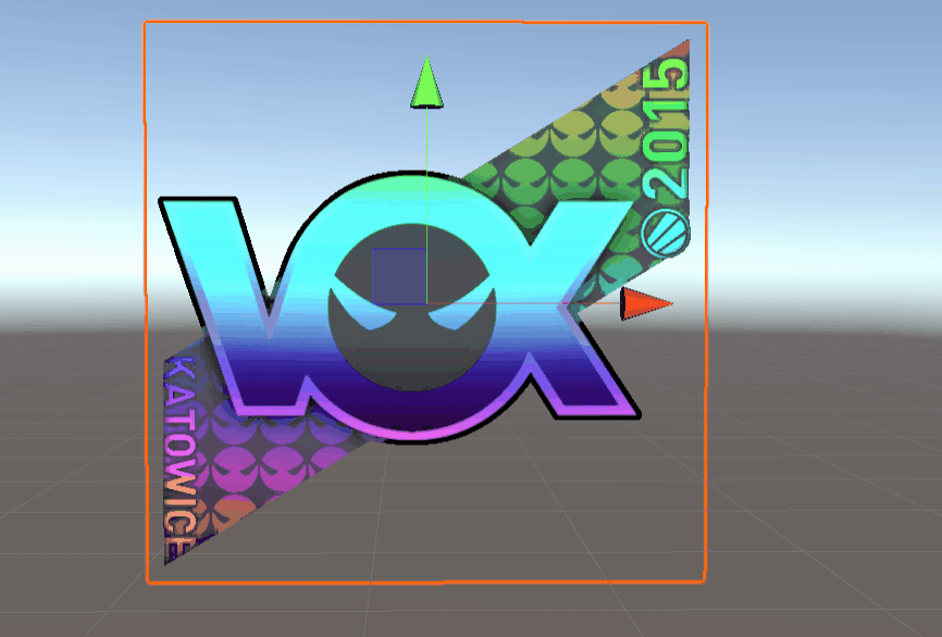
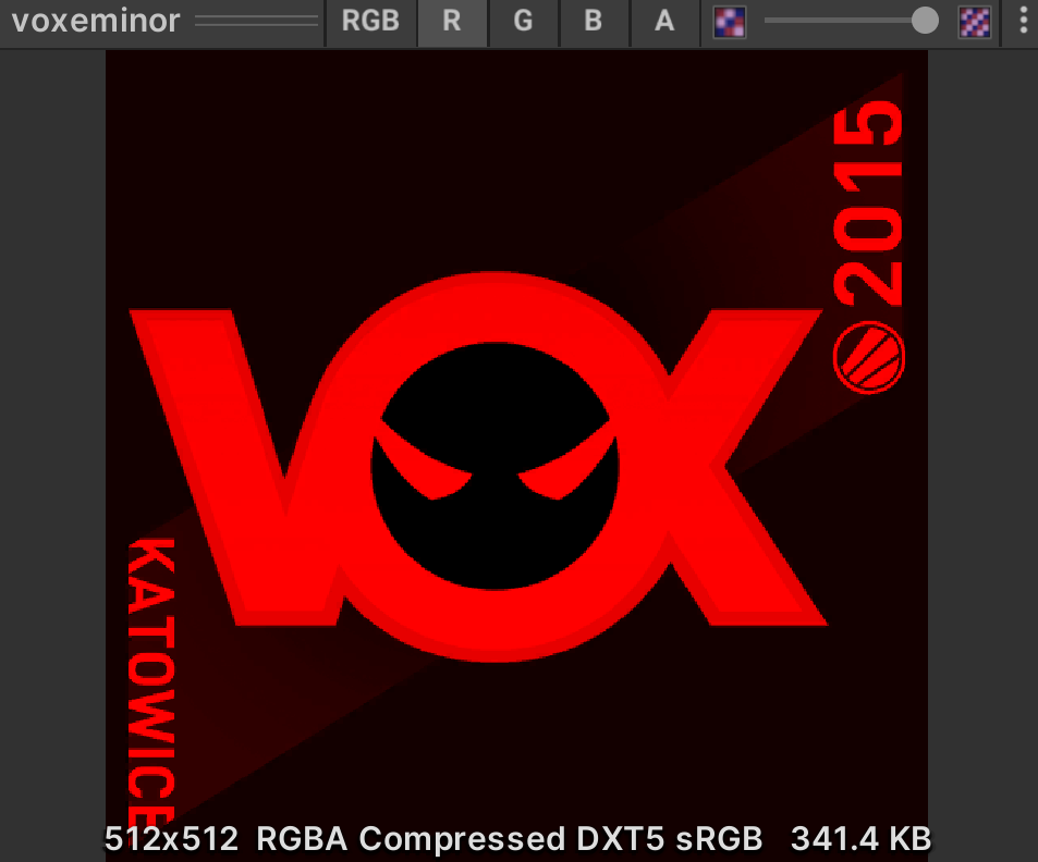
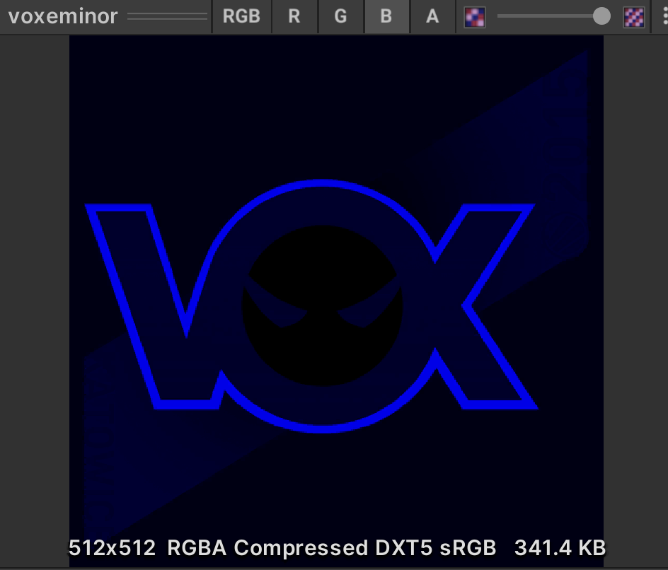
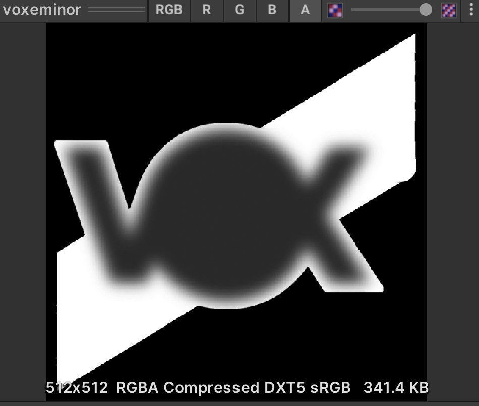
↑ these two figures are used as masks. According to the observation, it is considered to be a three-layer holo superposition, corresponding to the rgb channel of the mask.
2.1 holographic effect
We made a sub graph for the holographic effect:
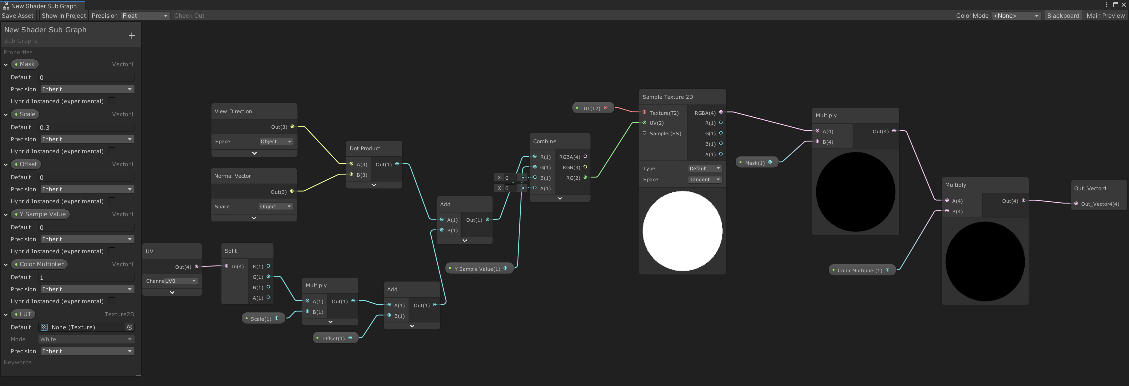
Explain the following parameters:
- Mask: where there is a holographic effect (1) and where there is no effect (0), a channel of the mask will be transmitted
- Scale: the speed of the sampling palette, that is, the speed of holo color change
- Offset: color offset
- Y Sample Value: the y value of the color palette
- Color Multiplier: multiplier of the obtained color
- LUT: look up table
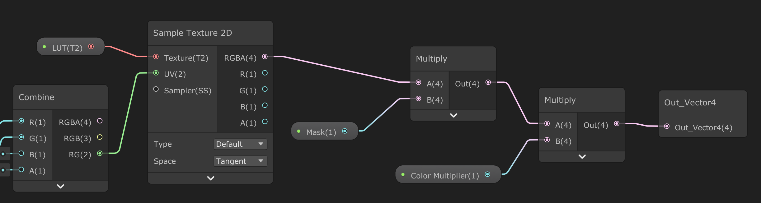
As shown in the figure below, compared with the usual method of uv sampling map, we will superimpose VdotN on uv to sample the color palette, so the change of viewing angle will affect the color selection. The inputs of the add node are VdotN and uv. Attention should be paid to VdotN in object space. If it changes in world space, it may be a precision problem caused by too large a value. uv there are two operations here. The first operation is because the color board samples directly, and the change direction of color is left and right. We need to change up and down, so we take y after uv split. The second operation is scale & offset. What I control here is the original uv, and readers can put it elsewhere.

As shown in the figure below, after sampling LUT, multiply by mask and color multiplier to get the final result.
2.2 multilayer holo stack
Next, read the three channels of the two mask s.

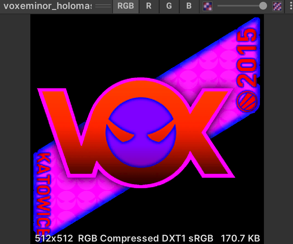

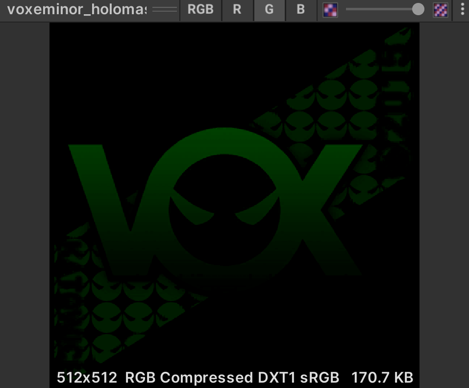
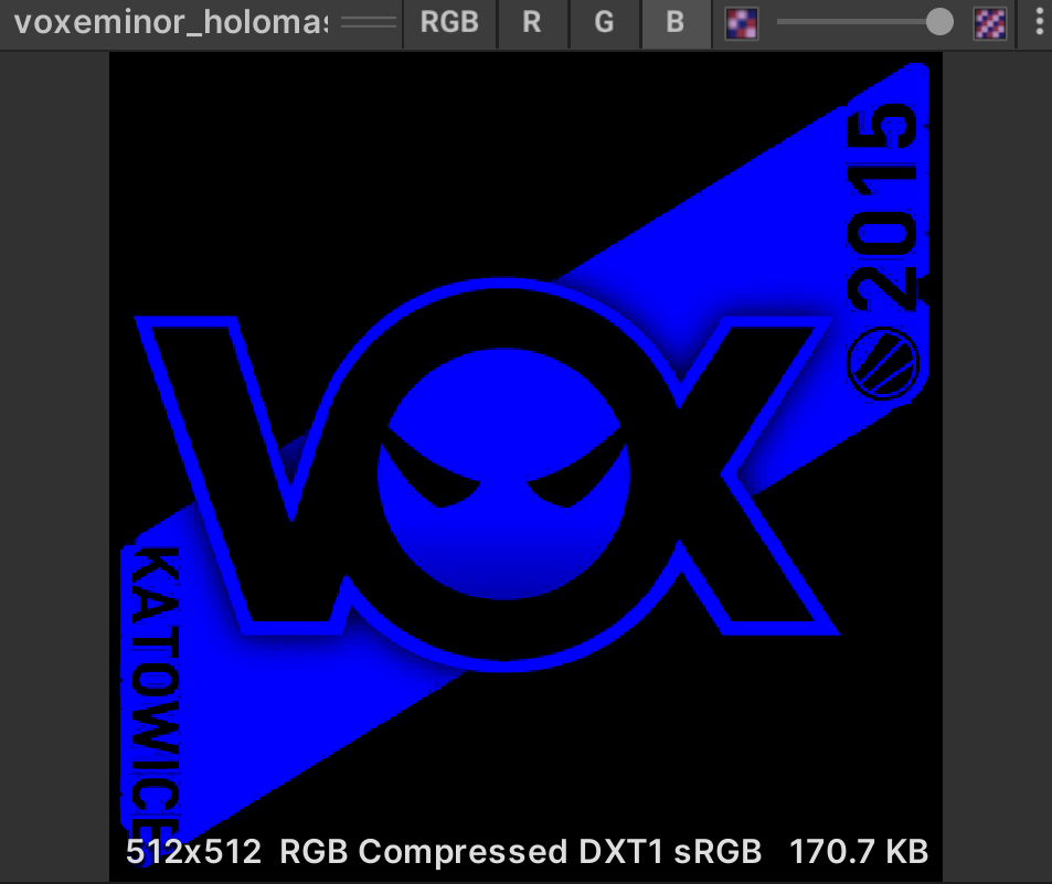
Readers can decide how to use these two pictures freely. My approach is like this. Not all pictures are used:
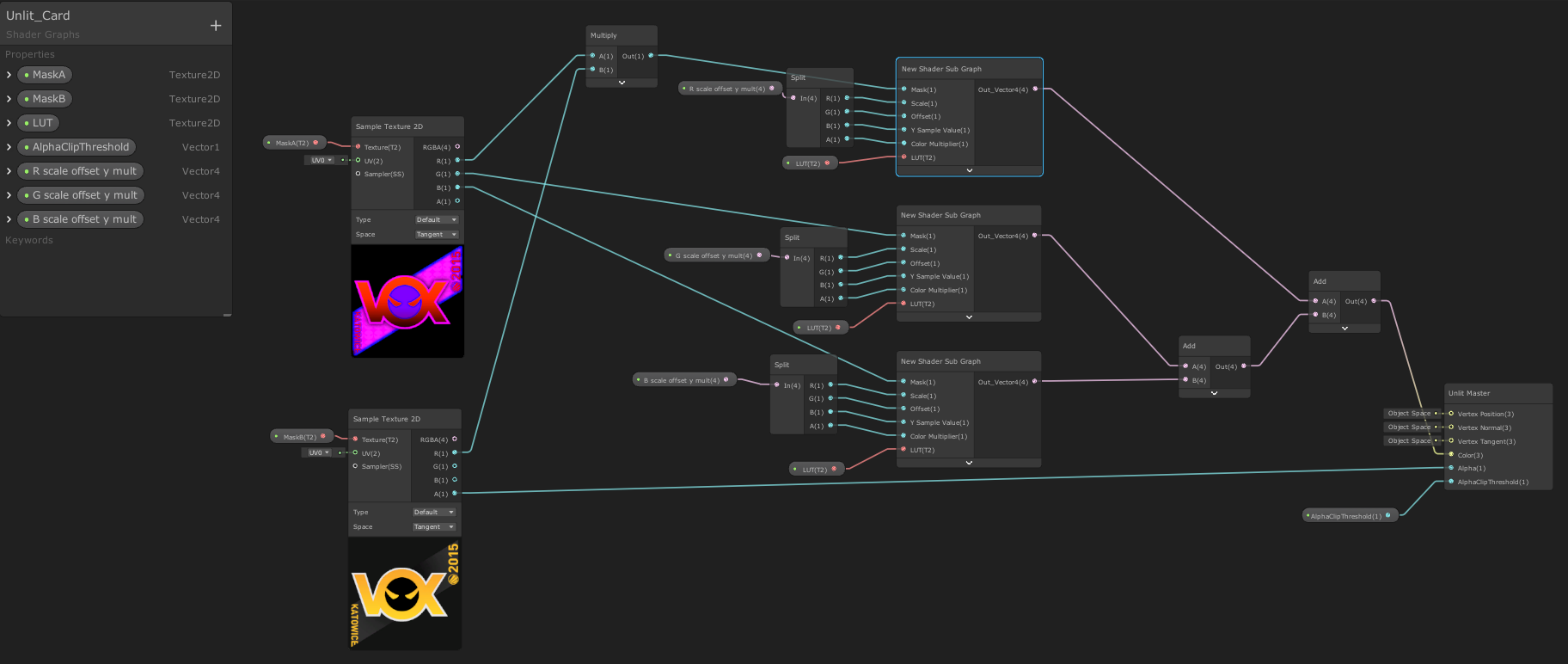
Parameters:
- R Scale Offset Y Mult: four parameters corresponding to the holo node


monolayer
superposition
2.3 convert to built-in pipeline shader
Shader "Unlit/UnlitShader card"
{
    Properties
    {
        _MaskA ("mask a", 2D) = "white" {}
        _MaskB ("mask b", 2D) = "white" {}
        _LUT ("LUT", 2D) = "white" {}
        RParam("R param", Vector) = (1, 0, 0, 1)
        GParam("G param", Vector) = (1, 0, 0, 1)
        BParam("B param", Vector) = (1, 0, 0, 1)
        _ClipValue("AlphaClipThreshold", Float) = 0
    }
    SubShader
    {
        Tags { "RenderType"="Opaque" }
        LOD 100

        Pass
        {
            CGPROGRAM
            #pragma vertex vert
            #pragma fragment frag

            #include "UnityCG.cginc"

            struct appdata
            {
                float4 vertex : POSITION;
                float3 normal : NORMAL;
                float2 uv : TEXCOORD0;
            };

            struct v2f
            {
                float2 uv : TEXCOORD0;
                UNITY_FOG_COORDS(1)
                float4 vertex : SV_POSITION;
                float3 normal : TEXCOORD1;
            };

            sampler2D _MaskA;
            sampler2D _MaskB;
            sampler2D _LUT;
            float4 RParam;
            float4 GParam;
            float4 BParam;
            float _ClipValue;


            v2f vert (appdata v)
            {
                v2f o;
                o.vertex = UnityObjectToClipPos(v.vertex);
                o.uv = v.uv;//TRANSFORM_TEX(v.uv, _MaskA);
                o.normal = v.normal;
                UNITY_TRANSFER_FOG(o,o.vertex);
                return o;
            }

            fixed4 Holo(half2 uv, float3 normal, half mask, half4 param)
            {
                half viewAngle=dot(_WorldSpaceCameraPos.xyz, normal);
                float2 calc_uv = float2(uv.y*param.x + param.y+viewAngle, param.z);
                return tex2D(_LUT, calc_uv) * mask * param.w;
            }
            fixed4 frag (v2f i) : SV_Target
            {
                half4 maskB = tex2D(_MaskB, i.uv);
                clip(maskB.a - _ClipValue);

                half4 maskA = tex2D(_MaskA, i.uv);

                half4 holoR = Holo(i.uv, i.normal, maskA.r * maskB.r, RParam);
                half4 holoG = Holo(i.uv, i.normal, maskA.g, GParam);
                half4 holoB = Holo(i.uv, i.normal, maskA.b, BParam);

                fixed4 col = half4((holoR+holoG+holoB).rgb, maskB.a);
                return col;
            }
            ENDCG
        }
    }
}
4. Summary and review
Calculation of viewing angle: the change of viewing angle can also be expressed by sin value, but point multiplication is very convenient, so cos is used