preface
Tip: the learning content comes from the following literature
catlikecoding.com
Tip: the following is the main content of this article. The following cases can be used for reference
1.1 project construction
In unity, February 2019 To create a new 3D project in version 6 or later, we will create our own pipeline, so do not select a URP project template. Once the project is open, you can go to the package manager and delete all packages you don't need. We will only try to draw the UI using the Unity UI package in this tutorial, so you can keep the UI.
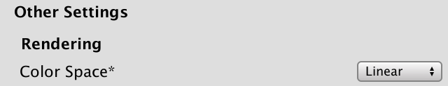
We will only use linear color space, but Unity 2019.2 still uses gamma space as the default. Go to player settings by editing / item settings, then player, and then switch to other settings section of color space linearity:
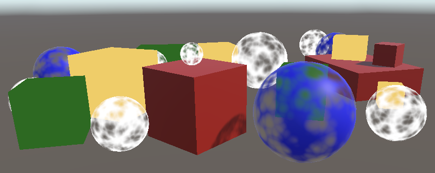
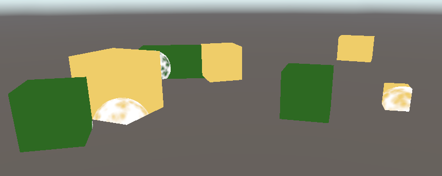
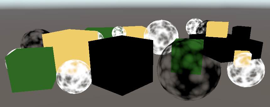
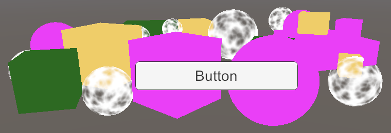
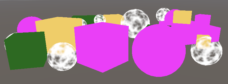
Fill the default scene with some objects, mixing standard, opaque and transparent materials. The non illuminated / transparent shader works only on textures, so there is a UV sphere map:
I put some cubes in my test scenario. They are opaque. Red uses Standard materials, while green and yellow use non shading / color shader materials. The blue sphere uses a Standard shader whose rendering mode is set to transparent, while the white sphere uses a non bright / transparent shader
2.1 pipeline asset
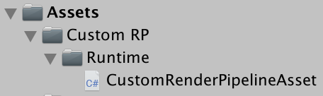
Currently, Unity uses the default rendering pipeline. To replace it with a custom rendering pipeline, we must first create an asset type for it. We will use roughly the same folder structure, the common RP currently used by Unity. Use the Runtime subfolder to create a custom RP asset folder and put the CustomRenderPipelineAsset into the Runtime subfolder.
The asset type must inherit from the RenderPipelineAsset namespace extension, unityengine Rendering
using UnityEngine;
using UnityEngine.Rendering;

public class CustomRenderPipelineAsset : RenderPipelineAsset {}
The main purpose of RP assets is to provide Unity with a method to obtain the pipeline object instance responsible for rendering. The asset itself is just a handle and a location to store settings. We don't have any settings yet, so all we have to do is give Unity a method to get an instance of the pipe object. This is achieved by overriding the abstract CreatePipeline method, which should return a RenderPipeline instance. However, we haven't defined a custom RP type yet, so we start from returning null.
The CreatePipeline method is defined using the protected access modifier, which means that only the class that defines the method, RenderPipelineAsset, and the class that extends the method can access the method.
	protected override RenderPipeline CreatePipeline () {
		return null;
	}
Now we need to add this type of asset to the project. To achieve this, add the CreateAssetMenu attribute to the CustomRenderPipelineAsset:
[CreateAssetMenu]
public class CustomRenderPipelineAsset : RenderPipelineAsset { ... }
This places an entry in the asset / create menu. Let's tidy it up and put it in the rendering submenu. To do this, we set the menunname property of the property to Rendering/Custom Render Pipeline. This property can be set directly after the property type, in parentheses
[CreateAssetMenu(menuName = "Rendering/Custom Render Pipeline")]
public class CustomRenderPipelineAsset : RenderPipelineAsset { ... }
Use the new menu item to add the asset to the project, then go to the Graphics project settings and select it under script render pipeline settings:
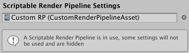
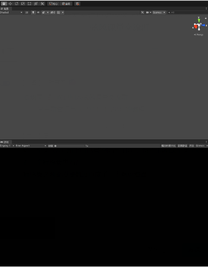
Replacing the default RP changes something. First, many options have disappeared from the graphics settings, as mentioned in the information panel. Secondly, we have disabled the default RP, but no effective replacement is provided, so nothing will be rendered. The game window, scene window, and material preview are no longer valid. If you open the framework debugger through Window/Analysis/Frame debugger and enable it, you will find that nothing is drawn in the game window:
2.2 render pipeline instance
Create a CustomRenderPipeline class and place its script file in the same folder as the CustomRenderPipelineAsset. This will be the type used by the RP instance returned by our asset, so it must extend RenderPipeline
using UnityEngine;
using UnityEngine.Rendering;

public class CustomRenderPipeline : RenderPipeline {}
RenderPipeline defines a protected Abstract Render method. We must override this method to create a concrete pipe. It has two parameters: a ScriptableRenderContext and a Camera array. Now leave this method empty
	protected override void Render (
		ScriptableRenderContext context, Camera[] cameras
	) {}
Create a CustomRenderPipelineAsset. CreatePipeline returns a new CustomRenderPipeline instance. This will provide us with an effective and usable pipeline, although it can't present anything yet
	protected override RenderPipeline CreatePipeline () {
		return new CustomRenderPipeline();
	}
3.0 rendering
Unity calls the rendered RP instance for each frame. It passes a context structure and provides a connection to the local engine, which we can use for rendering. It also passes a camera array because there may be multiple active cameras in the scene. It is RP's responsibility to render all these cameras in the order they provide.
3.1. Camera renderer
Each camera renders independently. Therefore, instead of letting CustomRenderPipeline Render all the cameras, we might as well transfer this responsibility to a new class for specially rendered cameras. Name it CameraRenderer and give it a public Render method with context and camera parameters. For convenience, we store these parameters in fields for later use
using UnityEngine;
using UnityEngine.Rendering;

public class CameraRenderer {

	ScriptableRenderContext context;

	Camera camera;

	public void Render (ScriptableRenderContext context, Camera camera) {
		this.context = context;
		this.camera = camera;
	}
}
Let CustomRenderPipeline create an instance when creating the renderer, and then use it to render all cameras in a loop
	CameraRenderer renderer = new CameraRenderer();

	protected override void Render (
		ScriptableRenderContext context, Camera[] cameras
	) {
		foreach (Camera camera in cameras) {
			renderer.Render(context, camera);
		}
	}
Our camera renderer is roughly equivalent to the script renderer of universal RP. This method will make it easy for each camera to support different rendering methods in the future, such as first person view and 3d map overlay, or forward and delayed rendering. But now we will render all the cameras in the same way
3.2. Drawing the skybox
CameraRenderer.Render is to draw all the geometry. For clarity, isolate specific tasks into a separate DrawVisibleGeometry method. We first let it draw the default skybox, which can be accomplished by calling DrawSkybox and camera in context.
	public void Render (ScriptableRenderContext context, Camera camera) {
		this.context = context;
		this.camera = camera;

		DrawVisibleGeometry();
	}

	void DrawVisibleGeometry () {
		context.DrawSkybox(camera);
	}
This doesn't make skybox display yet. This is because the commands we issue to the context are buffered. We must submit the work queued for execution by calling submit on the context. Let's do this in a separate Submit method, which is called after DrawVisibleGeometry.
	public void Render (ScriptableRenderContext context, Camera camera) {
		this.context = context;
		this.camera = camera;

		DrawVisibleGeometry();
		Submit();
	}

	void Submit () {
		context.Submit();
	}
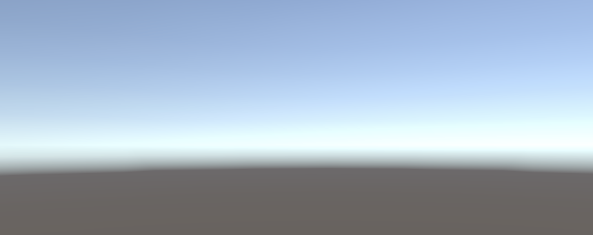
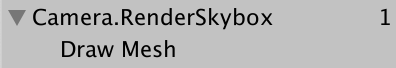
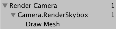
The skybox eventually appears in the game and scene windows. When you enable it, you can also see its entries in the framework debugger. Its name is camera Renderskybox, there is a Draw Mesh item below, which represents the actual Draw call. This corresponds to the rendering of the game window. The frame debugger does not report drawings in other windows
Note that the current orientation of the camera does not affect the way skybox renders. We send the camera to DrawSkybox, but it is only used to determine whether the sky box should be drawn. This is controlled by the camera's Clear Flags
In order to correctly render the sky box and the whole scene, we must establish a view projection matrix. This transformation matrix combines the position and direction of the camera -- the view matrix -- and the perspective or orthographic projection of the camera -- the projection matrix. It is called unity in shaders_ Matrixvp, which is one of the shader attributes used when drawing geometry. This matrix can be viewed in the ShaderProperties section of the framework debugger when a drawing call is selected
Currently, unity_ The matrixvp matrix is always the same. We must apply the camera's properties to the context through the SetupCameraProperties method. It sets the matrix and some other properties. Invoke in a separate Setup method and do this before DrawVisibleGeometry.
	public void Render (ScriptableRenderContext context, Camera camera) {
		this.context = context;
		this.camera = camera;

		Setup();
		DrawVisibleGeometry();
		Submit();
	}

	void Setup () {
		context.SetupCameraProperties(camera);
	}

3.3. Command buffers
The context delays the actual rendering until we commit it. Before that, we configure it and add commands to it for later execution. Some tasks (such as drawing skybox) can be issued through dedicated methods, but other commands must be issued indirectly through a separate command buffer. We need such a buffer to draw other geometry in the scene.
To get the buffer, we must create a new instance of the CommandBuffer object. We only need one buffer, so by default we create one for CameraRenderer and store a reference to it in the field. Also give the buffer a name so that we can identify it in the framework debugger. Just render the camera.
	const string bufferName = "Render Camera";

	CommandBuffer buffer = new CommandBuffer {
		name = bufferName
	};
How does the object initializer syntax work?
This is written as if we had called the constructor and then set buffer Name = buffername is written as a separate statement. However, when you create a new object, you can attach a code block to the call to the constructor. You can then set the fields and attributes of the object in the block without explicitly referencing the object instance. It makes it clear that instances should be used only after these fields and properties are set.
We can use the command buffer to inject profiler samples, which will be displayed in both profiler and frame debugger. This is done by calling BeginSample and EndSample at the appropriate points. In our example, this is the beginning of Setup and Submit. You must provide the same example name for both methods, and we'll use the name of the buffer.
	void Setup () {
		buffer.BeginSample(bufferName);
		context.SetupCameraProperties(camera);
	}

	void Submit () {
		buffer.EndSample(bufferName);
		context.Submit();
	}
To execute the buffer, use the buffer as a parameter to call ExecuteCommandBuffer in context. This will copy the command from the buffer without clearing it, and if we want to reuse it, we must do so explicitly later. Because execution and cleanup are always done together, it is convenient to add a method to do both:
	void Setup () {
		buffer.BeginSample(bufferName);
		ExecuteBuffer();
		context.SetupCameraProperties(camera);
	}

	void Submit () {
		buffer.EndSample(bufferName);
		ExecuteBuffer();
		context.Submit();
	}

	void ExecuteBuffer () {
		context.ExecuteCommandBuffer(buffer);
		buffer.Clear();
	}
Now, camera Renderskybox samples are nested in Render Camera:
3.4 clearing the render target
No matter what we draw, it will eventually be rendered to the rendering target of the camera. This is the default frame buffer, but it can also be a rendered texture. What was attracted to the target earlier is still there, which may interfere with the image we render now. In order to ensure correct rendering, we must clear the rendering target to remove its old content. This is done by calling ClearRenderTarget on the command buffer, which belongs to the Setup method.
CommandBuffer.ClearRenderTarget requires at least three parameters. The first two indicate whether the depth and color data should be cleared, which is correct for both. The third parameter is the color used to clear, for which we will use color clear.
	void Setup () {
		buffer.BeginSample(bufferName);
		buffer.ClearRenderTarget(true, true, Color.clear);
		ExecuteBuffer();
		context.SetupCameraProperties(camera);
	}
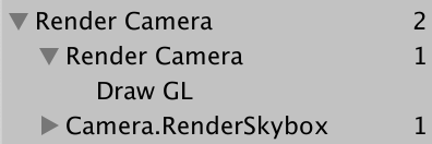
The frame debugger now displays a Draw GL entry for the cleanup action, which is nested in an extra level of the rendering camera. This happens because ClearRenderTarget wraps the cleanup in the example with the name of the command buffer. Before starting our own example, we can eliminate redundant nesting by cleaning up. This results in two adjacent render camera sample ranges that are merged:
	void Setup () {
		buffer.ClearRenderTarget(true, true, Color.clear);
		buffer.BeginSample(bufferName);
		//buffer.ClearRenderTarget(true, true, Color.clear);
		ExecuteBuffer();
		context.SetupCameraProperties(camera);
	}
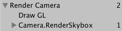
The Draw GL entry indicates that a full screen quadrilateral is drawn using the Hidden/InternalClear shader, which is written to the render target, which is not the most effective way to clear it. This method is used because we need to clean up before setting camera properties. If we exchange the order of these two steps, we get a fast cleaning method.
	void Setup () {
		context.SetupCameraProperties(camera);
		buffer.ClearRenderTarget(true, true, Color.clear);
		buffer.BeginSample(bufferName);
		ExecuteBuffer();
		//context.SetupCameraProperties(camera);
	}
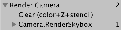
Now we see Clear (color+Z+stencil), which indicates that both the color buffer and the depth buffer have been cleared. Z represents the depth buffer, and the template data is part of the same buffer.
3.5 culling
What we see now is the sky box, not any object we put into the scene. Instead of drawing every object, we will only render those visible to the camera. We start with all the objects in the scene with renderer components, and then eliminate those objects that fall outside the cone of view of the camera.
To figure out what can be eliminated that requires us to track multiple camera settings and matrices, we can use the ScriptableCullingParameters structure. We can call TryGetCullingParameters on the camera instead of filling it ourselves. It returns whether the parameter can be successfully retrieved because it may fail to degenerate camera settings. In order to obtain the parameter data, we must provide it as an output parameter and write it out earlier. This operation is performed in a separate Cull method that returns success or failure.
	bool Cull () {
		ScriptableCullingParameters p
		if (camera.TryGetCullingParameters(out p)) {
			return true;
		}
		return false;
	}
Why write out?
When the struct parameter is defined as an output parameter, it acts like an object reference, pointing to the location on the memory stack where the parameter is located
When used as an output parameter, variable declarations can be inline in the parameter list, so let's do this:
	bool Cull () {
		//ScriptableCullingParameters p
		if (camera.TryGetCullingParameters(out ScriptableCullingParameters p)) {
			return true;
		}
		return false;
	}
Call Cull before rendering Setup, and abort if it fails.
	public void Render (ScriptableRenderContext context, Camera camera) {
		this.context = context;
		this.camera = camera;

		if (!Cull()) {
			return;
		}

		Setup();
		DrawVisibleGeometry();
		Submit();
	}
The actual elimination is done by calling Cull in the context, which produces a CullingResults structure. If successful, do so in cull and store the results in a field. In this case, we must pass the culling parameter as a reference parameter by writing ref in front of the parameter:
	CullingResults cullingResults;

	...

	bool Cull () {
		if (camera.TryGetCullingParameters(out ScriptableCullingParameters p)) {
			cullingResults = context.Cull(ref p);
			return true;
		}
		return false;
	}
Why use ref?
The ref keyword works the same way as out, except that the method does not need to assign anything new to it. The person calling the method is first responsible for properly initializing the value. Therefore, it can be used for input or output.
In this example, ref is used as an optimization item to prevent passing a copy of the ScriptableCullingParameters structure, which is quite large.
3.6 drawing geometry
Once we know what is visible, we can continue rendering these things. This is done by calling DrawRenderers in context and using the filter result as a parameter to tell which renderer it is used to complete. In addition, we must also provide drawing settings and filtering settings. Both are structures -- DrawingSettings and FilteringSettings -- and we'll use their default constructors first. Both must be passed by reference. Before drawing the skybox, do this in DrawVisibleGeometry:
	void DrawVisibleGeometry () {
		var drawingSettings = new DrawingSettings();
		var filteringSettings = new FilteringSettings();

		context.DrawRenderers(
			cullingResults, ref drawingSettings, ref filteringSettings
		);

		context.DrawSkybox(camera);
	}
We haven't seen anything yet because we must also indicate which shader channels are allowed. Since we only support unlit shaders in this tutorial, we must obtain the shader label ID for the srpddefaultunlit channel. We can do this once and cache it in a static field:
static ShaderTagId unlitShaderTagId = new ShaderTagId("SRPDefaultUnlit");
Provide it as the first parameter of the DrawingSettings constructor and a new SortingSettings structure value. Pass the camera to the constructor of the sort setting because it is used to determine whether orthographic or distance based sorting is applied:
	void DrawVisibleGeometry () {
		var sortingSettings = new SortingSettings(camera);
		var drawingSettings = new DrawingSettings(
			unlitShaderTagId, sortingSettings
		);
		...
	}
In addition, we must indicate which rendering queues are allowed. Set renderqueuerange All is passed to the FilteringSettings constructor to contain everything:
var filteringSettings = new FilteringSettings(RenderQueueRange.all);
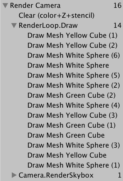
Only visible objects using the unlit shader will be painted. All drawing calls are listed in the frame debugger and grouped in renderloop Draw. Transparent objects are strange, but let's first look at the order in which objects are drawn. This is displayed by the frame debugger. You can select one drawing call after another or use the arrow keys:
Stepping framework debugger video
The drawing sequence is chaotic. We can force a specific drawing order by setting the criteria property of the sorting setting. Let's use sortingcriteria CommonOpaque
		var sortingSettings = new SortingSettings(camera) {
			criteria = SortingCriteria.CommonOpaque
		};
Stepping framework debugger video
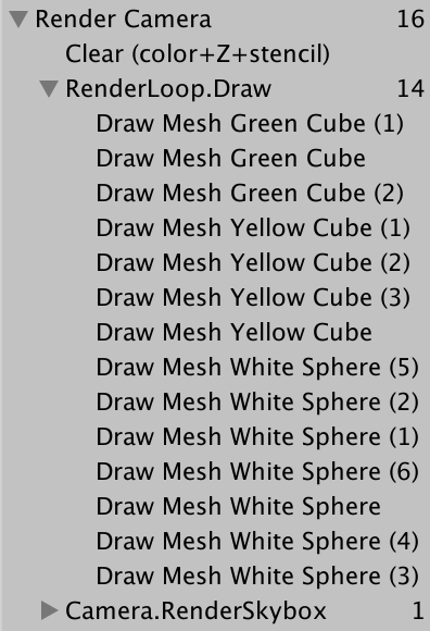
Objects are now drawn more or less from front to back, which is ideal for opaque objects. If something is eventually drawn behind something else, its hidden fragments can be skipped, which will speed up rendering. Common opaque sorting options also consider other criteria, including rendering queues and materials.
3.7 drawing opaque and transparent geometry separately
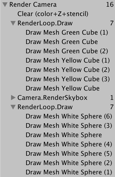
The frame debugger tells us that transparent objects will be drawn, but the sky box will be drawn in front of all opaque objects. The skybox is drawn behind the opaque geometry, so all its hidden fragments can be skipped, but it covers the transparent geometry. This is because the transparent shader does not write to the depth buffer. They don't hide behind them because we can see through them. The solution is to draw opaque objects first, then sky boxes, and then transparent objects.
By switching to renderqueuerange Opaque, we can eliminate transparent objects from the initial DrawRenderers call:
var filteringSettings = new FilteringSettings(RenderQueueRange.opaque);
Then call DrawRenderers again after drawing the skybox. But before that, change the render queue range to renderqueuerange transparent. Also change the sorting criteria to sorting criteria. CommonTransparent and set the sorted drawing settings again. This reverses the drawing order of transparent objects:
		context.DrawSkybox(camera);

		sortingSettings.criteria = SortingCriteria.CommonTransparent;
		drawingSettings.sortingSettings = sortingSettings;
		filteringSettings.renderQueueRange = RenderQueueRange.transparent;

		context.DrawRenderers(
			cullingResults, ref drawingSettings, ref filteringSettings
		);
Stepping framework debugger video
Why is the Drawcall order reversed?
Since transparent objects are not written to the depth buffer, there is no performance benefit to sort them before and after. However, when transparent objects visually interact with each other, they must be painted in front in order to be correctly integrated.
4.0. Editor rendering
Our RP can draw unlit objects correctly, but we can do something to improve the experience of using it in the Unity editor
4.1. Drawing legacy shaders
Because our pipeline only supports unlit shader channels, objects using different channels are not rendered, making them invisible. Although this is correct, it hides the fact that some objects in the scene use the wrong shader. Let's render them separately.
If someone starts with a default Unity project and then switches to our RP, they may use the wrong shader in the scene. In order to overr id e all default shaders for Unity, we must use shader tag IDs for Always, ForwardBase, PrepassBase, Vertex, VertexLMRGBM, and VertexLM channels. Track these in a static array:
	static ShaderTagId[] legacyShaderTagIds = {
		new ShaderTagId("Always"),
		new ShaderTagId("ForwardBase"),
		new ShaderTagId("PrepassBase"),
		new ShaderTagId("Vertex"),
		new ShaderTagId("VertexLMRGBM"),
		new ShaderTagId("VertexLM")
	};
Draw all unsupported shaders in a separate method after DrawVisibleGeometry. Because these are invalid passes, the result will be wrong, so we don't care about other settings. We can use filteringsettings The DefaultValue property gets the default filter settings:
	public void Render (ScriptableRenderContext context, Camera camera) {
		...

		Setup();
		DrawVisibleGeometry();
		DrawUnsupportedShaders();
		Submit();
	}

	...

	void DrawUnsupportedShaders () {
		var drawingSettings = new DrawingSettings(
			legacyShaderTagIds[0], new SortingSettings(camera)
		);
		var filteringSettings = FilteringSettings.defaultValue;
		context.DrawRenderers(
			cullingResults, ref drawingSettings, ref filteringSettings
		);
	}
We can draw multiple channels by calling SetShaderPassName on the drawing settings and taking the drawing order index and tag as parameters. Do this for all channels in the array, starting from the second, because we have set the first channel when constructing the drawing settings:
		var drawingSettings = new DrawingSettings(
			legacyShaderTagIds[0], new SortingSettings(camera)
		);
		for (int i = 1; i < legacyShaderTagIds.Length; i++) {
			drawingSettings.SetShaderPassName(i, legacyShaderTagIds[i]);
		}
Objects rendered with standard shaders will be displayed, but they are now pure black because our RP does not set the required shader attributes for them.
4.2. Error material
To clearly indicate which objects use unsupported shaders, we will paint them with Unity's wrong shader. Construct a new material with that shader as a parameter, and we can find it by calling the shader. Find using the Hidden/InternalErrorShader string as a parameter. Cache the material through a static field so that we don't create a new one at each frame. Then assign it to the overrides property of the drawing settings:
	static Material errorMaterial;

	...

	void DrawUnsupportedShaders () {
		if (errorMaterial == null) {
			errorMaterial =
				new Material(Shader.Find("Hidden/InternalErrorShader"));
		}
		var drawingSettings = new DrawingSettings(
			legacyShaderTagIds[0], new SortingSettings(camera)
		) {
			overrideMaterial = errorMaterial
		};
		...
	}
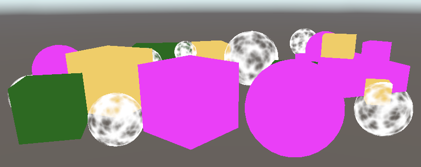
Now, all invalid objects are visible and obviously wrong.
4.4 partial class
Drawing invalid objects is useful for development, but not for published applications. So let's put all of CameraRenderer's editor only code in a separate partial class file. First copy the original CameraRenderer script resource and rename it CameraRenderer Editor
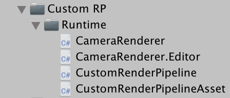
Then turn the original CameraRenderer into a partial class and remove the tag array, the wrong material, and the DrawUnsupportedShaders method from it
public partial class CameraRenderer { ... }
What is the Bureau category?
This is a method to split a class or structure definition into multiple parts, which are stored in different files. Its only purpose is to organize code. A typical use case is to separate automatically generated code from manually written code. As far as the compiler is concerned, it is all part of the same class definition.
Clean up the other partial class file so that it contains only what we deleted from the other partial class file
using UnityEngine;
using UnityEngine.Rendering;

partial class CameraRenderer {

	static ShaderTagId[] legacyShaderTagIds = {	... };

	static Material errorMaterial;

	void DrawUnsupportedShaders () { ... }
}
The content of the editor only needs to exist in the editor, so make it in the unit_ There are conditions on Editor:
partial class CameraRenderer {

#if UNITY_EDITOR

	static ShaderTagId[] legacyShaderTagIds = { ... }
	};

	static Material errorMaterial;

	void DrawUnsupportedShaders () { ... }

#endif
}
However, the build will fail at this point because the other part always contains a call to drawunsupported shaders, which now exists only in the editor. In order to solve this problem, we make this method partial. For this purpose, we always declare partial before the method signature, which is similar to the abstract method declaration. We can do this in any part of the class definition, so let's put it in the Editor section. The complete method declaration must also be marked with partial:
	partial void DrawUnsupportedShaders ();

#if UNITY_EDITOR

	...

	partial void DrawUnsupportedShaders () { ... }

#endif
The compilation build is now successful. The compiler removes all partial method calls that do not end with a full declaration.
4.5 drawing gizmos
At present, our RP cannot draw gizmos, either in the scene window or in the game window. If they are enabled:
We can call unityeditor Handles. Shouldrendergizmos to check whether gizmos should be drawn. If so, we must call DrawGizmos with the camera as a parameter in the context, plus a second parameter to indicate which gizmo subset should be drawn. There are two subsets, before and after the image effect. Because we don't support image effects now, we'll call both. Do this in a new editor only DrawGizmos method.
using UnityEditor;
using UnityEngine;
using UnityEngine.Rendering;

partial class CameraRenderer {

	partial void DrawGizmos ();

	partial void DrawUnsupportedShaders ();

#if UNITY_EDITOR

	...

	partial void DrawGizmos () {
		if (Handles.ShouldRenderGizmos()) {
			context.DrawGizmos(camera, GizmoSubset.PreImageEffects);
			context.DrawGizmos(camera, GizmoSubset.PostImageEffects);
		}
	}

	partial void DrawUnsupportedShaders () { ... }

#endif
}
This gadget should rank behind everything else:
	public void Render (ScriptableRenderContext context, Camera camera) {
		...

		Setup();
		DrawVisibleGeometry();
		DrawUnsupportedShaders();
		DrawGizmos();
		Submit();
	}
4.6. Drawing unity UI
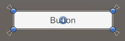
Another thing we need to pay attention to is Unity's game internal user interface. For example, create a simple UI by adding a button to GameObject / UI / button. It appears in the game window, but not in the scene window:
The frame debugger shows us that the UI is presented separately, not by RP:
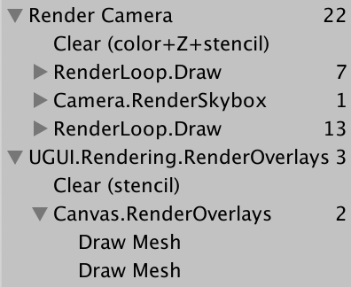
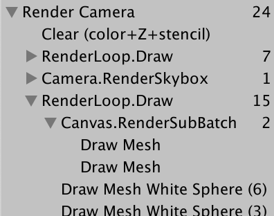
At least, this is the default when the rendering mode of the canvas component is set to screen space overlay. Changing it to screen space camera and using the master camera as its rendering camera will make it part of transparent geometry:
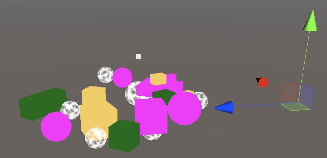
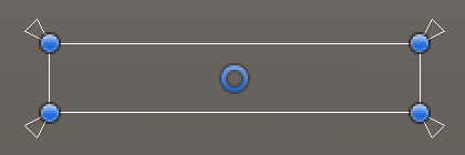
When rendering the world in the scene window, the UI always uses the World Space mode, which is why it eventually becomes very large. However, although we can edit the UI through the scene window, it will not be drawn:
When rendering the scene window, we must explicitly add the UI to the world geometry by calling ScriptableRenderContext. EmitWorldGeometryForSceneView, camera as parameter. Do this in a new editor only PrepareForSceneWindow method. When its cameraType property is equal to cameraType When using the SceneView, we use the scene camera for rendering:
#if UNITY_EDITOR

	...

	partial void PrepareForSceneWindow () {
		if (camera.cameraType == CameraType.SceneView) {
			ScriptableRenderContext.EmitWorldGeometryForSceneView(camera);
		}
	}
Because this may add geometry to the scene, it must be done before culling:
		PrepareForSceneWindow();
		if (!Cull()) {
			return;
		}
5.0, multiple cameras
There can be multiple active cameras in the scene. If so, we must make sure they work together
5.1 two cameras
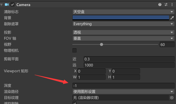
Each camera has a "Depth" parameter, and the default main camera is "− 1". They are presented in the order of increasing Depth. To see this, copy the primary camera, rename it the secondary camera, and set its Depth to 0. It's also a good idea to give it another label, because MainCamera should only be used by one camera.
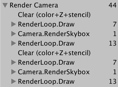
The scene is now rendered twice. The final image is still the same because the render target is cleared in between. The frame debugger shows this, but because adjacent sample scopes with the same name are merged, we end up with a separate render camera scope.
It would be clearer if each camera had its own sight. To do this, add an editor only PrepareBuffer method that makes the name of the buffer equal to the name of the camera:
	partial void PrepareBuffer ();

#if UNITY_EDITOR

	...

	partial void PrepareBuffer () {
		buffer.name = camera.name;
	}

#endif
Call it before we PrepareForSceneWindow:
		PrepareBuffer();
		PrepareForSceneWindow();
5.2. Processing with changing buffer names
Although frame debug now shows a separate sample hierarchy for each camera, when we enter game mode, Unity's console will be filled with messages warning us that BeginSample and EndSample counts must match. Because we use different names to represent samples and their buffers, it is easy to be confused. In addition, we will allocate memory every time we access the camera's name attribute, so we don't want to do this in the build
To solve these two problems, you need to add a SampleName string attribute. If in the editor, set it and the name of the buffer in PrepareBuffer, otherwise it is just a constant alias assigned to the camera string:
#if UNITY_EDITOR

	...

	string SampleName { get; set; }

	...

	partial void PrepareBuffer () {
		buffer.name = SampleName = camera.name;
	}

#else

	const string SampleName = bufferName;

#endif
Use SampleName for samples in Setup and Submit
	void Setup () {
		context.SetupCameraProperties(camera);
		buffer.ClearRenderTarget(true, true, Color.clear);
		buffer.BeginSample(SampleName);
		ExecuteBuffer();
	}

	void Submit () {
		buffer.EndSample(SampleName);
		ExecuteBuffer();
		context.Submit();
	}
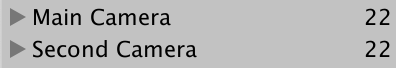
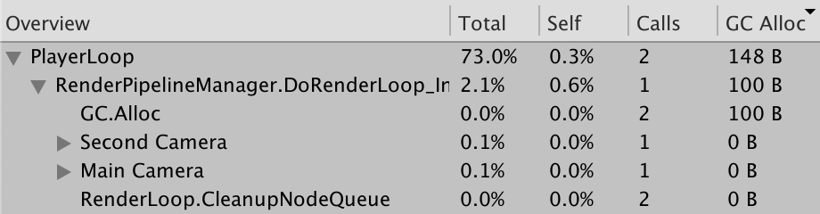
We can see the difference by checking the profiler program (opened through Window / Analysis / profiler) and playing it first in the editor. Switch to hierarchical mode and sort by GC Alloc column. You will see entries for two GC calls. Alloc, a total of 100 bytes are allocated, which is caused by retrieving the camera name. Further down, you will see these names displayed as samples: main camera and sub camera:
Next, enable Development build and Autoconnect Profiler to build. Play the build and make sure the profiler is connected and logged. In this case, instead of obtaining the allocation of 100 bytes, we obtained a single rendering camera sample:
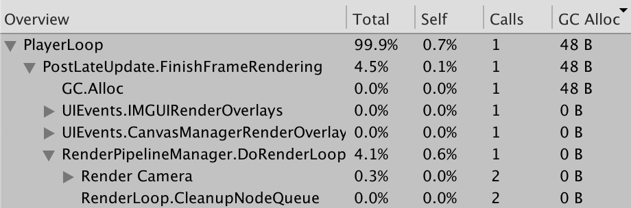
What is the allocation of the other 48 bytes?
It's an array of cameras we can't control. Its size depends on how many cameras are rendered.
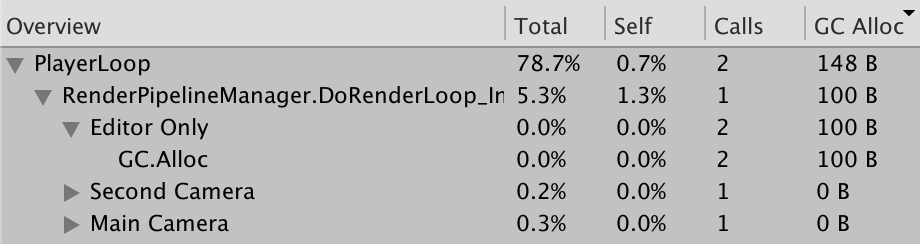
By wrapping the camera name in an analyzer example called Editor, you can make the example allocate memory only in the Editor, not after construction. In this case, we need to start from unityengine Profiling namespace calls profiler BeginSample and profiler EndSample. Only BeginSample needs to pass a name
We can clearly show that we allocate memory only in the editor, not in the build, by encapsulating camera name retrieval in an analyzer example called editor only. In this case, we need to call Profiler. BeginSample and parser. EndSample of UnityEngine. Configure the namespace. Only BeginSample needs to pass a name.
using UnityEditor;
using UnityEngine;
using UnityEngine.Profiling;
using UnityEngine.Rendering;

partial class CameraRenderer {

	...

#if UNITY_EDITOR

	...

	partial void PrepareBuffer () {
		Profiler.BeginSample("Editor Only");
		buffer.name = SampleName = camera.name;
		Profiler.EndSample();
	}

#else

	string SampleName => bufferName;

#endif
}
5.3 layers
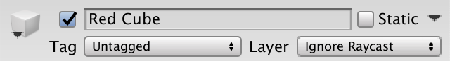
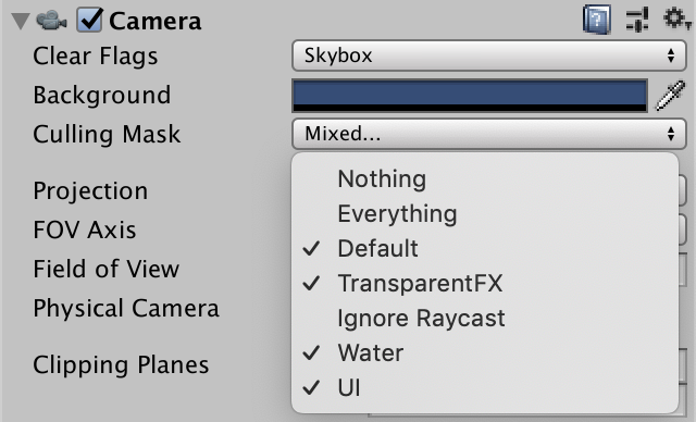
The camera can also be configured to see only things on a specific layer. This is done by adjusting their culling mask. Let's move all objects using standard shaders to the Ignore Raycast layer:
Exclude this layer from the culling mask of the main camera:
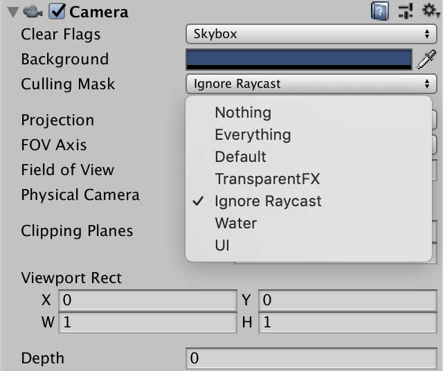
And make it the only layer visible to the second camera:
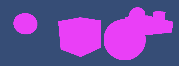
Because the secondary camera finally renders, we end up seeing only invalid objects:

5.4 clear flags
We can combine the results of the two cameras by adjusting the clear flag of the second rendered camera. They are defined by the CameraClearFlags enumeration and can be retrieved through the clearFlags attribute of the camera. Do this in setup before purging:
	void Setup () {
		context.SetupCameraProperties(camera);
		CameraClearFlags flags = camera.clearFlags;
		buffer.ClearRenderTarget(true, true, Color.clear);
		buffer.BeginSample(SampleName);
		ExecuteBuffer();
	}
The CameraClearFlags enumeration defines four values. From 1 to 4 are Skybox, Color, depth and Nothing. These are not actually independent flag values, but represent a reduction in the amount of cleaning. Except for the last one, the depth buffer must be cleared in all cases, so when the flags value is equal to or equal to depth:
		buffer.ClearRenderTarget(
			flags <= CameraClearFlags.Depth, true, Color.clear
		);
We only need to clear the color buffer when flags is set to color, because in the case of Skybox, we finally replaced all previous color data:
		buffer.ClearRenderTarget(
			flags <= CameraClearFlags.Depth,
			flags == CameraClearFlags.Color,
			Color.clear
		);
If we want to clear to solid color, we must use the background color of the camera. But because we render in linear color space, we have to convert color into linear space, so we finally need camera. backgroundcolor.linear. In all other cases, color is not important, so we can use color clear.
		buffer.ClearRenderTarget(
			flags <= CameraClearFlags.Depth,
			flags == CameraClearFlags.Color,
			flags == CameraClearFlags.Color ?
				camera.backgroundColor.linear : Color.clear
		);
Because the main camera is the first to render, its Clear Flags should be set to Skybox or Color. When the frame debugger is enabled, we always start with a clear buffer, but this is not guaranteed in general
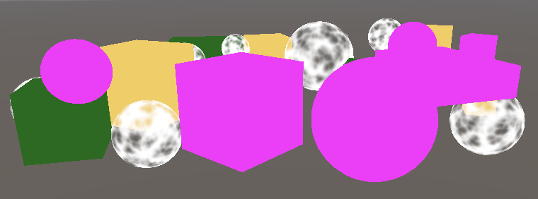
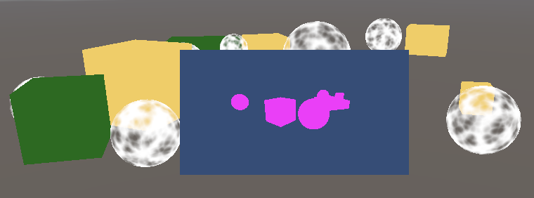
The clear flag of the Secondary Camera determines how to combine the rendering of the two cameras. In the case of skybox or color, the previous results are completely replaced. When only the depth is cleared, the Secondary Camera renders normally, except that it does not draw the sky box, so the previous results are displayed as the background. When nothing is cleared, the depth buffer is retained, so unlighted objects eventually block invalid objects as if they were drawn by the same camera. However, the transparent object drawn by the previous camera has no depth information, so it is drawn to the top, just like the previous sky box:
By adjusting the Viewport Rect of the camera, you can also reduce the rendering area to a small part of the entire rendering target. The rest of the render target is not affected. In this case, the Hidden/InternalClear shader is used to clear. The template buffer is used to limit rendering to the viewport area:
Please note that rendering multiple cameras in one frame means that culling, setting, sorting and other operations also need to be carried out many times. Generally speaking, the most effective method is to use a camera from a unique perspective.
!!! The first chapter is finally finished. Congratulations