Getting Start
In a digital circuit, 1 corresponds to a high-level signal and 0 corresponds to a low-level signal.
Verilog Language
Basic
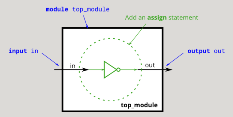
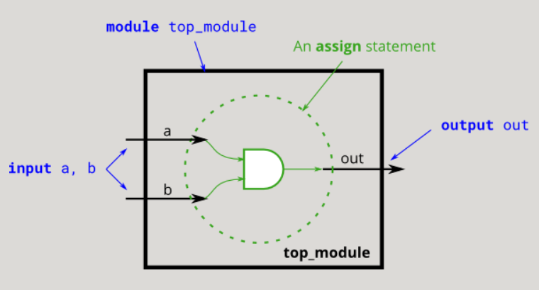
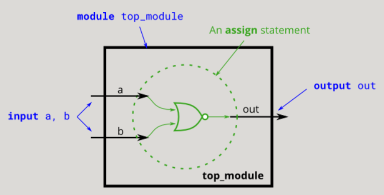
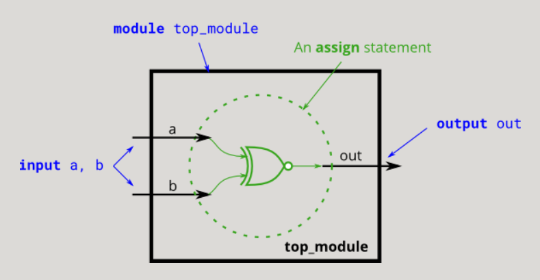
The keyword assign is used for continuous assignment
assign left_side = right_side
NOT gate, logic negates the symbol!, Bitwise inverse sign~
AND gate, logic and symbol & &, bitwise and symbol&
OR gate, logic or symbol, bitwise or symbol|
The following figure shows the NOR gate, that is, add a non on the basis of the OR gate
XNOR gate, logical or symbol^~
XOR gate, logical homor symbol^
The following figure shows the same or gate, which can be regarded as adding a non or gate to the XOR gate
Vectors
Vector declaration format: type [high: low] vector name
wire [99:0] my_vector; // Declare a 100-element vector
An undeclared vector will generate a Bug during use, and it is fixed to a bit width
wire [2:0] a, c;   // Two vectors
assign a = 3'b101;  // a = 101
assign b = a;       // b =   1  implicitly-created wire
assign c = b;       // c = 001  <-- bug
my_module i1 (d,e); // d and e are implicitly one-bit wide if not declared.
                    // This could be a bug if the port was intended to be a vector.
Disabling implicit declaration requires adding a macro definition
`default_nettype none
When declaring the reg memory type, you can add the number of storage units after the reg vector name
reg [7:0] mem [255:0];   // There are 256 storage units, and each storage unit is an 8-bit reg
reg mem2 [28:0];         // There are 256 storage units, and each storage unit is a 1-bit reg
Vector partial selection operator [:]
assign out = my_vector[10]; // Part-select one bit out of the vector
Vector concatenation operator {,}, each element in the concatenation operator needs to be marked with bit width, otherwise it is illegal
assign {w,x,y,z} = {a,b,c,d,e,f,2'b11};
Vector copy operator format {num{Vector}}
assign out = ~{{5{a}},{5{b}},{5{c}},{5{d}},{5{e}}} ^ {5{a,b,c,d,e}};
Modules:Hierarchy
For the connection between parent and child modules, you need to instantiate child modules under the parent module
module mod_a ( input in1, input in2, output out ); //A mod is defined_ a
    // Module body
endmodule
There are two ways to instantiate a module: by location and by name
Instantiation by location refers to one-to-one correspondence between module ports and external signals from left to right. Obviously, the disadvantage of this method is that once the port list changes, the port connections in all module instantiations need to be adjusted.
Example format: module name and example name (external signal 1, external signal 2, external signal 3,..., external signal n);
mod_a instance1 ( wa, wb, wc );
Instantiation by name is to directly correspond the signal outside the module instance to the port name of the module. In this way, the port order can be arbitrary.
Example format: module name, instance name (. Port name (external signal),. Port name (),. Port name (external signal));
mod_a instance2 ( .out(wc), .in1(wa), .in2(wb) );
Full adder expression
assign sum = a^b^cin;
assign cout = a&b | a&cin | b&cin;
Of course, in order to be closer to the adder, the above code can be written as follows
assign {cout,sum} = a + b + cin;
Another half adder expression
assign sum  = a^b;
assign cout = a&b;
Procedures
Keyword always
The always statement is executed repeatedly. The always statement block executes the behavior statement from time 0; When the last statement is executed, the first statement in the statement block is executed again, and the cycle is repeated.
Combinational: always @(*)
Clocked: always @(posedge clk)
Due to the characteristics of loop execution, always statements are mostly used to simulate the generation of clock, the detection of signal behavior and so on.
always if statement
always @(*) begin
    if (condition) begin
        out = x;
        ...
    end
    else begin
        out = y;
        ...
    end
end
This is equivalent to the following successive assign statements
assign out = (condition) ? x : y;
always case statement
always @(*) begin     // This is a combinational circuit
    case (in)
      1'b1: begin
               out = 1'b1;  // begin-end if >1 statement
            end
      1'b0: out = 1'b0;
      default: out = 1'bx;
    endcase
end
always casez statement
always @(*) begin
    casez (in[3:0])
        4'bzzz1: out = 0;   // The upper three digits of the input in can be any value
        4'bzz1z: out = 1;
        4'bz1zz: out = 2;
        4'b1zzz: out = 3;
        default: out = 0;
    endcase
end
Latch
In the level triggered storage unit, the action of data storage depends on the level value of the input clock (or enable) signal. The output changes with the data input only when the latch is enabled.
When the level signal is invalid, the output signal changes with the input signal, just like passing through the buffer; When the level is valid, the output signal is latched. Any change of excitation signal will directly cause the change of latch output state, which is likely to produce oscillation due to the instability of transient characteristics.
Main hazards of Latch:
- The input state may change many times, which is easy to produce burrs, increasing the uncertainty of the next stage circuit;
- In most FPGA resources, more resources than triggers may be needed to implement Latch structure;
- The emergence of latches makes the static timing analysis more complex.
Ways to avoid Latch:
- If else or case statement, the structure must be complete
- Do not place the assignment signal in the assignment source or condition judgment
- For sensitive signal list, it is recommended to use always @ (*)
More Verilog Features
Ternary operator, similar to that in C language
(condition ? if_true : if_false)
Previously, I learned the bitwise operator between two values, but sometimes I need to bitwise operate on all bits of a vector
In fact, it is to add a bitwise operator in front of the vector, as follows
& a[3:0]     // AND: a[3]&a[2]&a[1]&a[0]. Equivalent to (a[3:0] == 4'hf)
| b[3:0]     // OR:  b[3]|b[2]|b[1]|b[0]. Equivalent to (b[3:0] != 4'h0)
^ c[2:0]     // XOR: c[2]^c[1]^c[0]
The advantage of this is that there is no need to write lengthy bitwise logic code
Loop for statement
for(initial_assignment; condition ; step_assignment)  begin
   ............
end