PLOT3D format
PLOT3D data format originated from NASA and is widely used in CFD data files with regular grids. ASCII or FORTRAN formatted files can also be used.
PLOT3D file is divided into grid file (XYZ file), aerodynamic result file (Q file) and general result file (function file + function name file). The so-called IBlank parameter can be added to the grid file.
Definition of IBlank parameter:
IBlank is a positive value given at each grid point, which is defined as follows:
| numerical value | significance |
|---|---|
| 0 | Non fluid points outside the computational domain |
| 1 | Normal point |
| 2 | Solid boundary point |
| negative | Block grid interface point, whose value is the block number of adjacent grid blocks |
For detailed PLOT3D format, see PLOT3D data format ;
PLOT3D in VTK
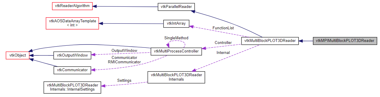
vtkMultiBlockPLOT3DReader
Read PLOT3D data file;
Vtkmultiblockplot3dreamer is a reader object used to read PLOT3D format files and generate structured meshes when outputting. PLOT3D is a computer graphics program designed to visualize computational fluid dynamics grids and solutions. The reader also supports variants of the PLOT3D format used by NASA's OVERFLOW CFD software, including full support for all Q variables. Please refer to the "PLOT3D user manual" provided by NASA Ames Research Center (Moffett, California).
PLOT3D files consist of raster files (also known as XYZ files), optional solution files (also known as Q files), and optional function files containing user created data (not currently supported). The Q file contains the following solution information: four parameters: free flow Mach number (Fsmach), angle of attack (Alpha), Reynolds number (Re) and total integration time (time). This information is stored in the array named Properties in each output FieldData (tuple 0:fsmach, tuple 1:alpha, tuple 2:re, tuple 3:time). In addition, the solution file contains flow density (scalar), flow volume (vector), and flow energy (scalar).
This reader supports limited forms of time series data, which are stored as a series of Q files. Using the AddFileName () method provided by the superclass, you can define a file family. For other cases, such as XYZ or function files that change over time, use vtkPlot3DMetaReader.
vtkMPIMultiBlockPLOT3DReader
Vtkmpimultiblockplot3dreamer class inherits from vtkmultiblockplot3dreamer class. It uses MPI-IO to efficiently read binary files in three-dimensional domain in parallel, and uses MPI-IO to replace ordinary POSIX IO to read PLOT3D files;
MPI (Message Passing Interface) is a set of specifications or interfaces used by developers to transfer messages between different CPU s or server nodes involved in computing in high-performance computing programs. Through this set of interfaces, it can help development engineers quickly write parallel computing programs that can be transplanted across platforms on different computing platforms and improve development efficiency. The original intention of the design is to enable IO to realize parallel data read-write access through standard interfaces like message passing (MPI).
vtkPlot3DMetaReader
Read meta file and point to PLOT3D file;
The main goal of this reader is to make it easy to read PLOT3D files, especially the time series of PLOT3D files. PLOT3D files can take many different forms according to their contents. Unfortunately, it is not a self describing format, so users need to pass information about the contents of the file to the reader. Usually, this is achieved by setting some member variables. The goal of this reader is to provide a simple format that enables the writer of PLOT3D files to describe their settings and group multiple files into a time series. Note that for binaries, the auto detect format option (enabled by default) does not need to specify most of the other options. However, the reader is still very useful when trying to read a sequence of files, even binary files. The format of this metafile is very simple and based on JSON (you can understand this format without knowing JSON). The following is an example with comments describing the format (followed by / /). Note the location of PLOT3D file names relative to the metafile, unless they begin with a leading /.
#include <vtkActor.h>
#include <vtkCamera.h>
#include <vtkMultiBlockDataSet.h>
#include <vtkMultiBlockPLOT3DReader.h>
#include <vtkNamedColors.h>
#include <vtkNew.h>
#include <vtkPolyData.h>
#include <vtkPolyDataMapper.h>
#include <vtkProperty.h>
#include <vtkRenderWindow.h>
#include <vtkRenderWindowInteractor.h>
#include <vtkRenderer.h>
#include <vtkStructuredGridGeometryFilter.h>
class Test_Probing
{
public:
static void Test()
{
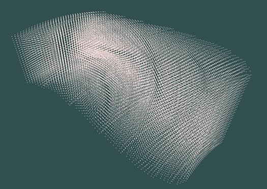
std::string xyzFile = "G:\\Data\\VTK\\combxyz.bin";
std::string qFile = "G:\\Data\\VTK\\combq.bin";
vtkNew<vtkNamedColors> colors;
vtkNew<vtkMultiBlockPLOT3DReader> reader;
reader->SetXYZFileName(xyzFile.c_str());
reader->SetQFileName(qFile.c_str());
reader->SetScalarFunctionNumber(100);
reader->SetVectorFunctionNumber(202);
reader->Update();
vtkNew<vtkStructuredGridGeometryFilter> geometryFilter;
geometryFilter->SetInputData(reader->GetOutput()->GetBlock(0));
geometryFilter->Update();
// Visualize
vtkNew<vtkPolyDataMapper> mapper;
mapper->SetInputConnection(geometryFilter->GetOutputPort());
mapper->ScalarVisibilityOff();
vtkNew<vtkActor> actor;
actor->SetMapper(mapper);
actor->GetProperty()->SetColor(colors->GetColor3d("MistyRose").GetData());
vtkNew<vtkRenderer> renderer;
vtkNew<vtkRenderWindow> renderWindow;
renderWindow->AddRenderer(renderer);
vtkNew<vtkRenderWindowInteractor> renderWindowInteractor;
renderWindowInteractor->SetRenderWindow(renderWindow);
renderer->AddActor(actor);
renderer->SetBackground(colors->GetColor3d("DarkSlateGray").GetData());
renderer->ResetCamera();
renderer->GetActiveCamera()->SetClippingRange(3.95297, 50);
renderer->GetActiveCamera()->SetFocalPoint(8.88908, 0.595038, 29.3342);
renderer->GetActiveCamera()->SetPosition(-12.3332, 31.7479, 41.2387);
renderer->GetActiveCamera()->SetViewUp(0.060772, -0.319905, 0.945498);
renderWindow->SetWindowName("ReadPLOT3D");
renderWindow->SetSize(640, 480);
renderWindow->Render();
renderWindowInteractor->Start();
}
};
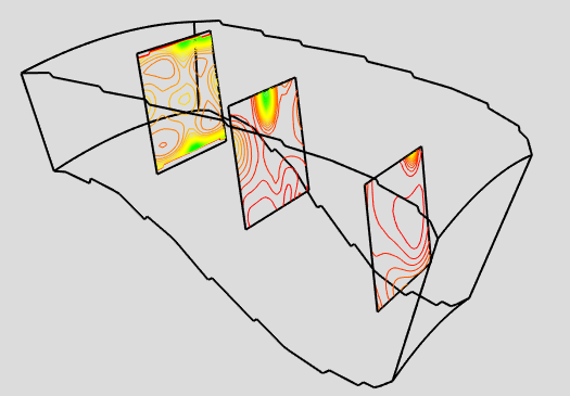
Probing obtains dataset attributes by sampling a dataset (input) with a set of points (probes). Detection is also called "resampling", for example, detecting an input data set with a sequence of points on a straight line, a plane or a volume. The result of the probe is a new dataset (output), which has the topology and geometry of the probe dataset and inserts point attributes from the input dataset. Once the probe operation is complete, you can use any appropriate technology in VTK to visualize the output data set.
This example illustrates the details of the detection process. For each point in the probe dataset, determine the position (i.e. cell, sub cell and parameter coordinates) and interpolation weight in the input dataset. Then the data values in the cell are interpolated to the detection point. Probe points outside the input dataset are specified as nil (or appropriate) values. This process is repeated for all points in the probe dataset.
#include <vtkActor.h>
#include <vtkAppendPolyData.h>
#include <vtkCamera.h>
#include <vtkContourFilter.h>
#include <vtkMultiBlockDataSet.h>
#include <vtkMultiBlockPLOT3DReader.h>
#include <vtkNamedColors.h>
#include <vtkNew.h>
#include <vtkOutlineFilter.h>
#include <vtkPlaneSource.h>
#include <vtkPolyDataMapper.h>
#include <vtkProbeFilter.h>
#include <vtkProperty.h>
#include <vtkRenderWindow.h>
#include <vtkRenderWindowInteractor.h>
#include <vtkRenderer.h>
#include <vtkStructuredGrid.h>
#include <vtkStructuredGridOutlineFilter.h>
#include <vtkTransform.h>
#include <vtkTransformPolyDataFilter.h>

class Test_Probing
{
public:
	static void Test()
	{
		std::string xyzFile = "G:\\Data\\VTK\\combxyz.bin";
		std::string qFile = "G:\\Data\\VTK\\combq.bin";
		vtkNew<vtkNamedColors> colors;

		// create pipeline
		//
		vtkNew<vtkMultiBlockPLOT3DReader> pl3d;
		pl3d->SetXYZFileName(xyzFile.c_str());
		pl3d->SetQFileName(qFile.c_str());
		pl3d->SetScalarFunctionNumber(100);
		pl3d->SetVectorFunctionNumber(202);
		pl3d->Update();

		vtkStructuredGrid* sg = dynamic_cast<vtkStructuredGrid*>(pl3d->GetOutput()->GetBlock(0));

		// We create three planes and position them in the correct position
		// using transform filters. They are then appended together and used as
		// a probe.
		vtkNew<vtkPlaneSource> plane;
		plane->SetResolution(50, 50);

		vtkNew<vtkTransform> transP1;
		transP1->Translate(3.7, 0.0, 28.37);
		transP1->Scale(5, 5, 5);
		transP1->RotateY(90);

		vtkNew<vtkTransformPolyDataFilter> tpd1;
		tpd1->SetInputConnection(plane->GetOutputPort());
		tpd1->SetTransform(transP1);

		vtkNew<vtkOutlineFilter> outTpd1;
		outTpd1->SetInputConnection(tpd1->GetOutputPort());

		vtkNew<vtkPolyDataMapper> mapTpd1;
		mapTpd1->SetInputConnection(outTpd1->GetOutputPort());

		vtkNew<vtkActor> tpd1Actor;
		tpd1Actor->SetMapper(mapTpd1);
		tpd1Actor->GetProperty()->SetColor(0, 0, 0);
		tpd1Actor->GetProperty()->SetLineWidth(2.0);

		vtkNew<vtkTransform> transP2;
		transP2->Translate(9.2, 0.0, 31.20);
		transP2->Scale(5, 5, 5);
		transP2->RotateY(90);

		vtkNew<vtkTransformPolyDataFilter> tpd2;
		tpd2->SetInputConnection(plane->GetOutputPort());
		tpd2->SetTransform(transP2);

		vtkNew<vtkOutlineFilter> outTpd2;
		outTpd2->SetInputConnection(tpd2->GetOutputPort());

		vtkNew<vtkPolyDataMapper> mapTpd2;
		mapTpd2->SetInputConnection(outTpd2->GetOutputPort());

		vtkNew<vtkActor> tpd2Actor;
		tpd2Actor->SetMapper(mapTpd2);
		tpd2Actor->GetProperty()->SetColor(0, 0, 0);
		tpd2Actor->GetProperty()->SetLineWidth(2.0);

		vtkNew<vtkTransform> transP3;
		transP3->Translate(13.27, 0.0, 33.30);
		transP3->Scale(5, 5, 5);
		transP3->RotateY(90);

		vtkNew<vtkTransformPolyDataFilter> tpd3;
		tpd3->SetInputConnection(plane->GetOutputPort());
		tpd3->SetTransform(transP3);

		vtkNew<vtkOutlineFilter> outTpd3;
		outTpd3->SetInputConnection(tpd3->GetOutputPort());

		vtkNew<vtkPolyDataMapper> mapTpd3;
		mapTpd3->SetInputConnection(outTpd3->GetOutputPort());

		vtkNew<vtkActor> tpd3Actor;
		tpd3Actor->SetMapper(mapTpd3);
		tpd3Actor->GetProperty()->SetColor(0, 0, 0);
		tpd3Actor->GetProperty()->SetLineWidth(2.0);

		vtkNew<vtkAppendPolyData> appendF;
		appendF->AddInputConnection(tpd1->GetOutputPort());
		appendF->AddInputConnection(tpd2->GetOutputPort());
		appendF->AddInputConnection(tpd3->GetOutputPort());

		// The vtkProbeFilter takes two inputs. One is a dataset to use as the probe
		// geometry (SetInputConnection); the other is the data to probe
		// (SetSourceConnection). The output dataset structure (geometry and
		// topology) of the probe is the same as the structure of the input. The
		// probing process generates new data values resampled from the source.
		vtkNew<vtkProbeFilter> probe;
		probe->SetInputConnection(appendF->GetOutputPort());
		probe->SetSourceData(sg);

		vtkNew<vtkContourFilter> contour;
		contour->SetInputConnection(probe->GetOutputPort());
		contour->GenerateValues(50, sg->GetScalarRange());

		vtkNew<vtkPolyDataMapper> contourMapper;
		contourMapper->SetInputConnection(contour->GetOutputPort());
		contourMapper->SetScalarRange(sg->GetScalarRange());

		vtkNew<vtkActor> planeActor;
		planeActor->SetMapper(contourMapper);

		vtkNew<vtkStructuredGridOutlineFilter> outline;
		outline->SetInputData(sg);

		vtkNew<vtkPolyDataMapper> outlineMapper;
		outlineMapper->SetInputConnection(outline->GetOutputPort());

		vtkNew<vtkActor> outlineActor;
		outlineActor->SetMapper(outlineMapper);
		outlineActor->GetProperty()->SetColor(0, 0, 0);
		outlineActor->GetProperty()->SetLineWidth(2.0);

		// Create the RenderWindow, Renderer and both Actors
		//
		vtkNew<vtkRenderer> ren1;

		vtkNew<vtkRenderWindow> renWin;
		renWin->AddRenderer(ren1);

		vtkNew<vtkRenderWindowInteractor> iren;
		iren->SetRenderWindow(renWin);

		ren1->AddActor(outlineActor);
		ren1->AddActor(planeActor);
		ren1->AddActor(tpd1Actor);
		ren1->AddActor(tpd2Actor);
		ren1->AddActor(tpd3Actor);
		ren1->SetBackground(colors->GetColor3d("Gainsboro").GetData());
		renWin->SetSize(640, 480);
		renWin->SetWindowName("ProbeCombustor");

		ren1->ResetCamera();
		ren1->GetActiveCamera()->SetClippingRange(3.95297, 50);
		ren1->GetActiveCamera()->SetFocalPoint(8.88908, 0.595038, 29.3342);
		ren1->GetActiveCamera()->SetPosition(-12.3332, 31.7479, 41.2387);
		ren1->GetActiveCamera()->SetViewUp(0.060772, -0.319905, 0.945498);

		renWin->Render();
		iren->Start();
	}
};
Used data file location: